Wiring harness, engine, Z19
|
|
Wiring harness, engine, Z19
|
|
|
•
|
Detach the negative cable from the battery.
|
|
|
•
|
Detach the positive cable the runs from positive battery terminal to the fuse box.
|
|
|
•
|
Remove the positive battery cable.
|
|
|
•
|
Undo the bolt of the battery lock lug and lift out the battery.
|
|
2.
|
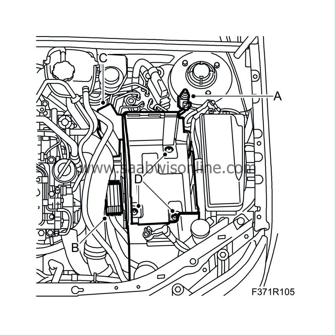
Remove the battery tray and components:
|
|
|
•
|
Undo the electrical connection of the bonnet switch (A).
|
|
|
•
|
Remove the glow plug relay (B).
|
|
|
•
|
Remove the fuse holder (C).
|
|
|
•
|
Remove the wiring harness cable tie from the battery tray.
|
|
|
•
|
Remove the battery tray (D).
|
|
3.
|
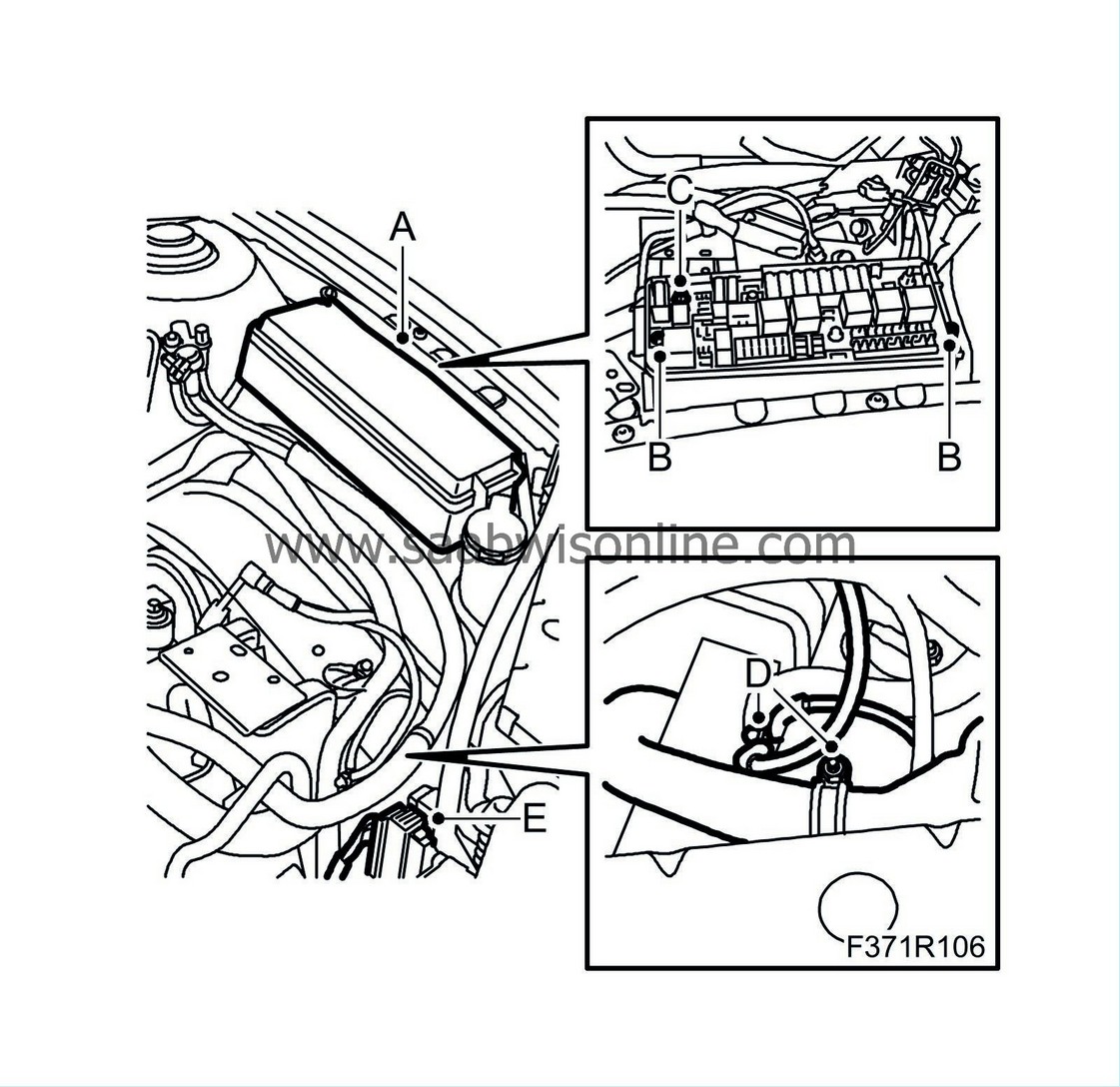
Undo the wiring and detach the fuse box:
|
|
|
•
|
Remove the fuse box cover (A).
|
|
|
•
|
Detach the fuse box (B).
|
|
|
•
|
Remove the front bolt of the fuse box (C).
|
|
|
•
|
Unplug the front connector beneath the fuse box.
|
|
|
•
|
Remove the hose clip (D) and ground connection (D) of the wiring that sits on the structural member.
|
|
|
•
|
Remove the connector (E) on the structural member.
|
|
4.
|
Man. gearbox:
Remove the connection of the reversing light switch.
|
|
5.
|
Remove the clips (A) and connections (B) of the radiator fans and charge air valve.
|
|
6.
|
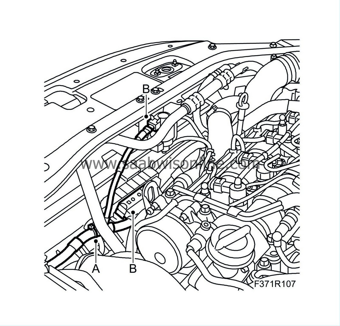
Remove the clips (A) and cable tie (B) that hold the wiring on the left side and rear of the engine.

|
|
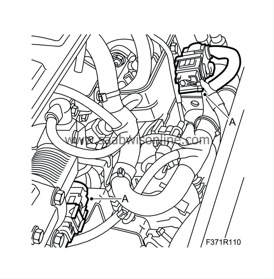
7.
|
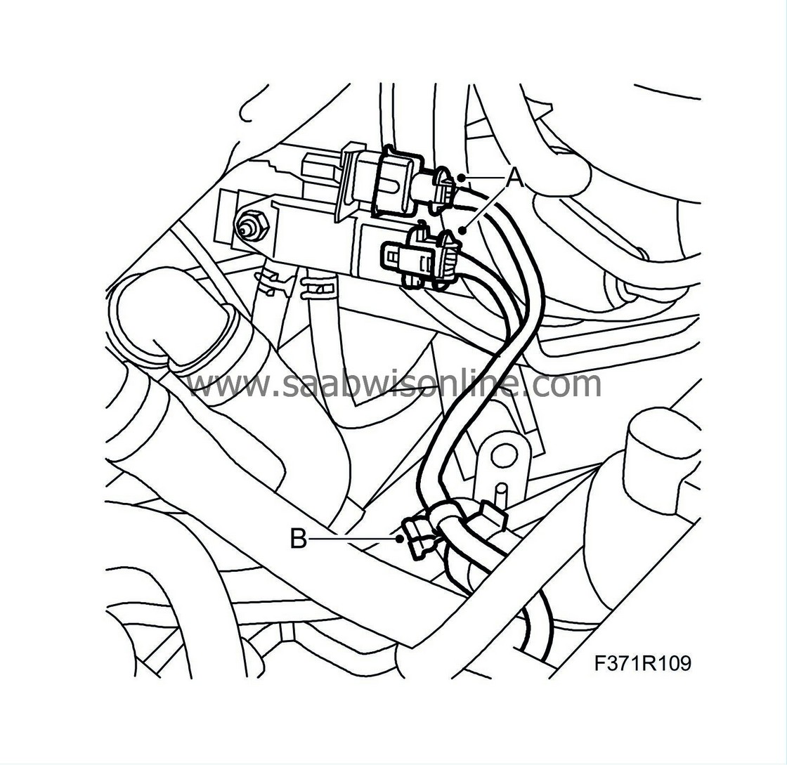
Unplug the connectors (A) of the pressure sensor for the particle trap and temperature sensor and remove the clip (B) from the water hose.
|
|
8.
|
Unplug the connectors (A) on the back of the engine.
|
|
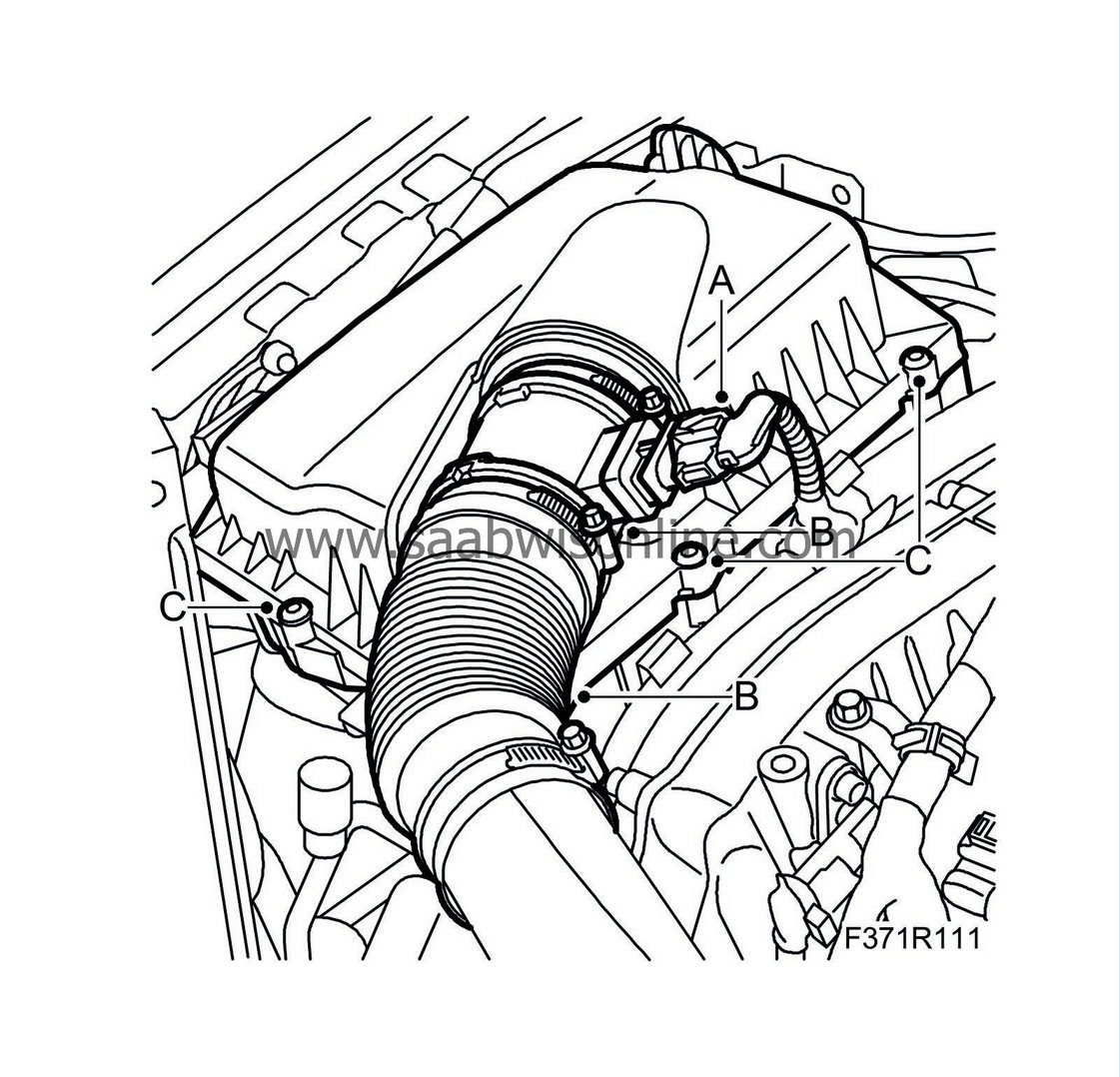
9.
|
Remove the air filter housing:
|
|
|
•
|
Unplug the connector (A) from the mass air flow sensor.
|
|
|
•
|
Undo the hose from the mass air flow sensor (B).
|
|
|
•
|
Remove the bolts (C) and lift out the air filter housing.
|
|
10.
|
Remove the clips (A) on the right rear structural member and the cable tie (B).
|
|
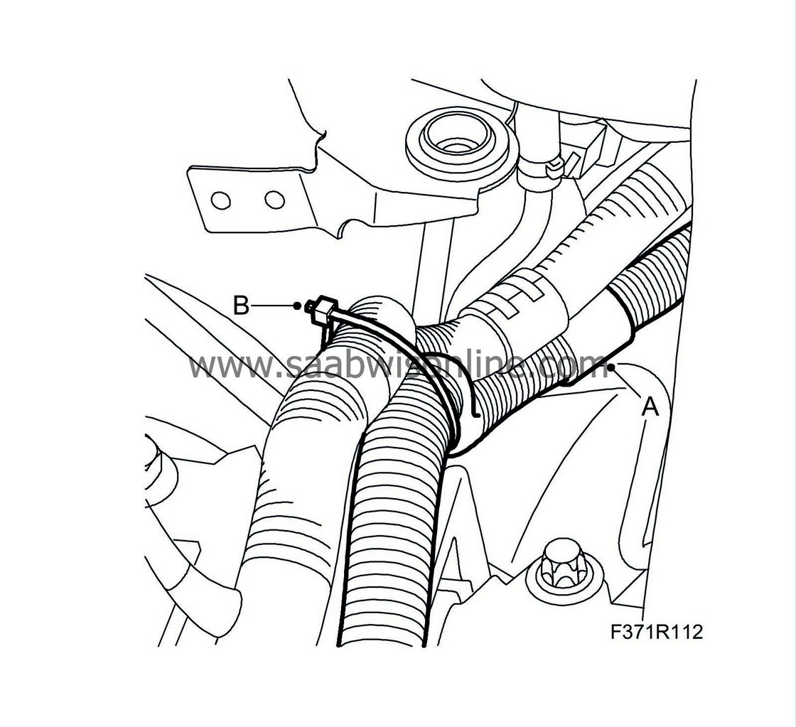
11.
|
Remove the connector (A) on the AC pipe and the clip (B) on the right structural member.
|
|
12.
|
Remove the clips (A) from the upper radiator member.

|
|
13.
|
Raise the vehicle to a suitable work height.
|
|
14.
|
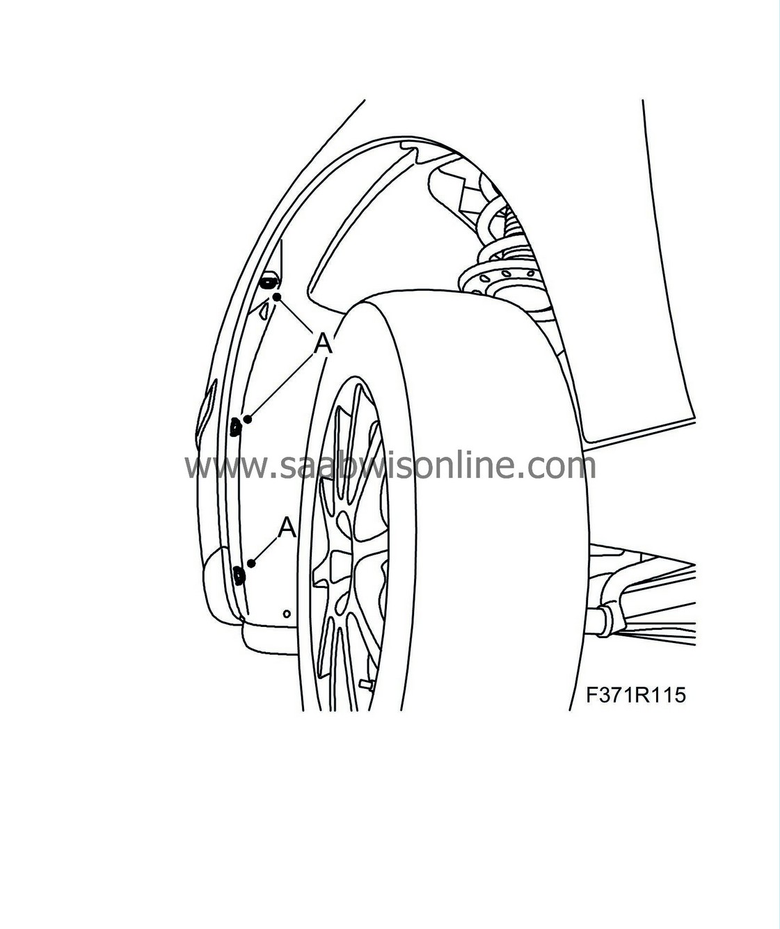
Remove the bumper bolts in the wing liner (A).
|
|
15.
|
Remove the spoiler shield (A). Unplug the connector (B) and remove the connector (C). Remove the lower engine cover (D).

|
|
16.
|
Cars with headlamp washer:
Detach the washer hose. Suspend and plug as necessary.
|
|
17.
|
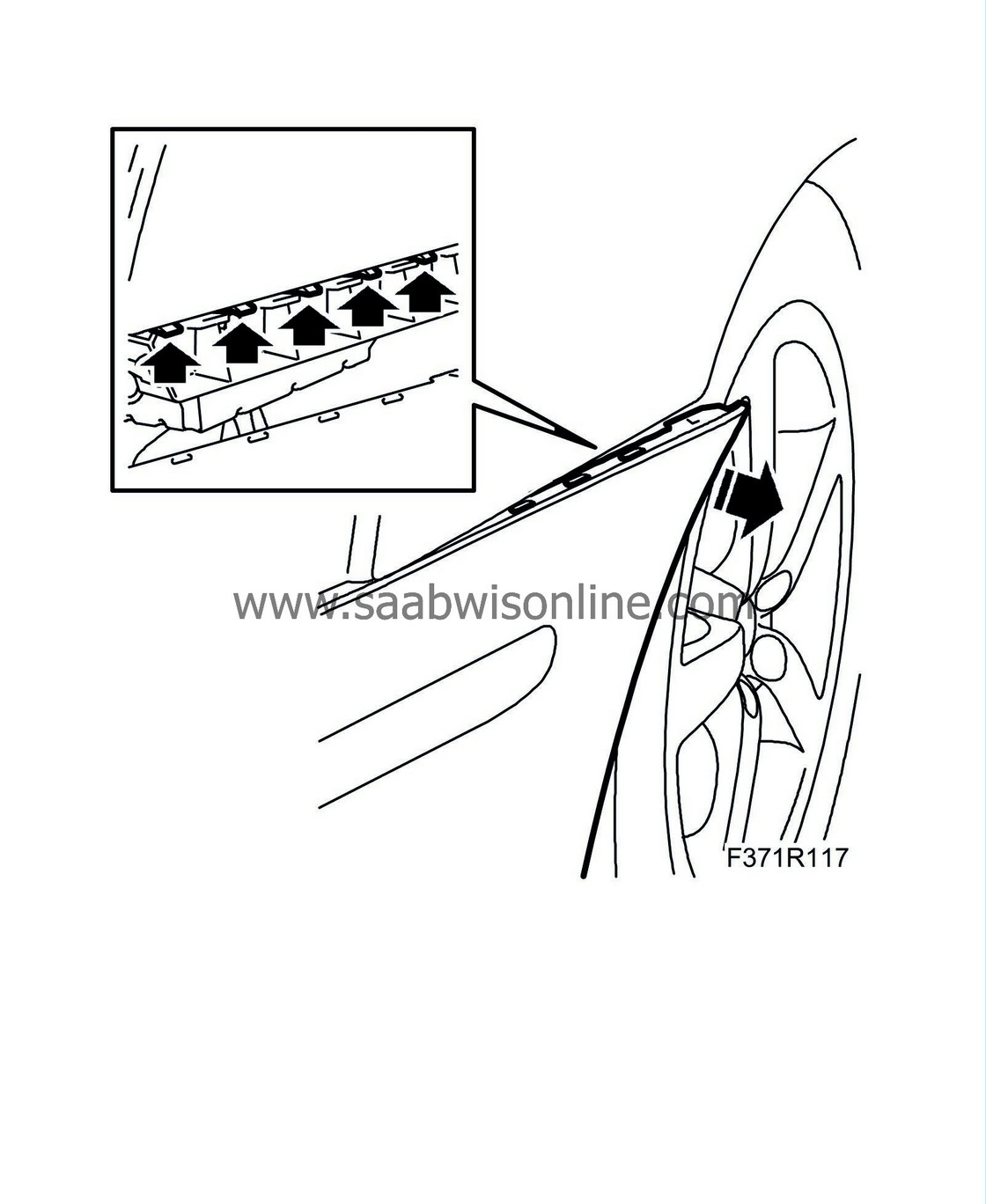
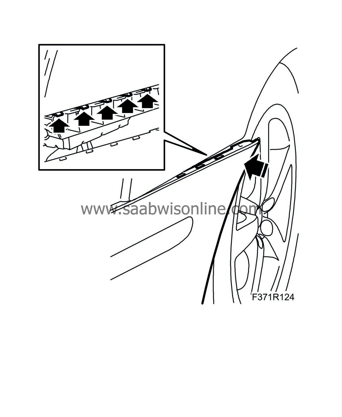
Pry the bumper shell corner from the holder bracket and lift off the bumper shell.
|
|
18.
|
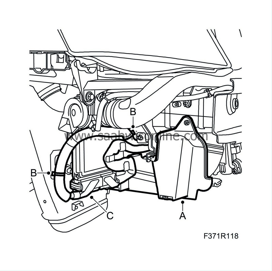
Remove the right side cover and detach the wiring:
|
|
|
•
|
Remove the right side cover (A).
|
|
|
•
|
Remove the cable tie (B) holding the wiring around the control module.
|
|
|
•
|
Remove the right control module connection (C).
|
|
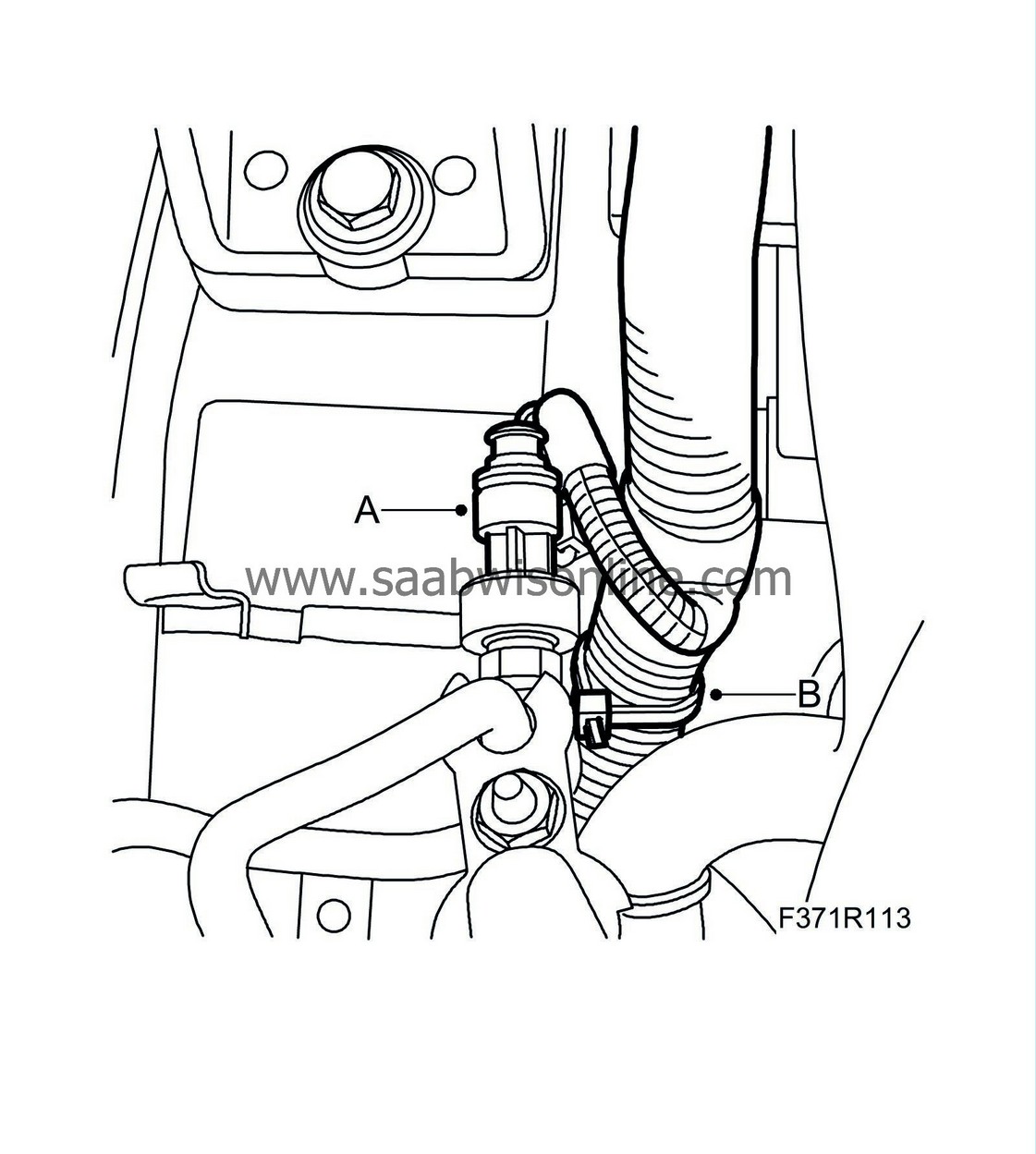
19.
|
Remove the bracket (A) protecting the AC compressor wiring. Release the wiring so that it hangs freely down in the engine bay.
|
|
20.
|
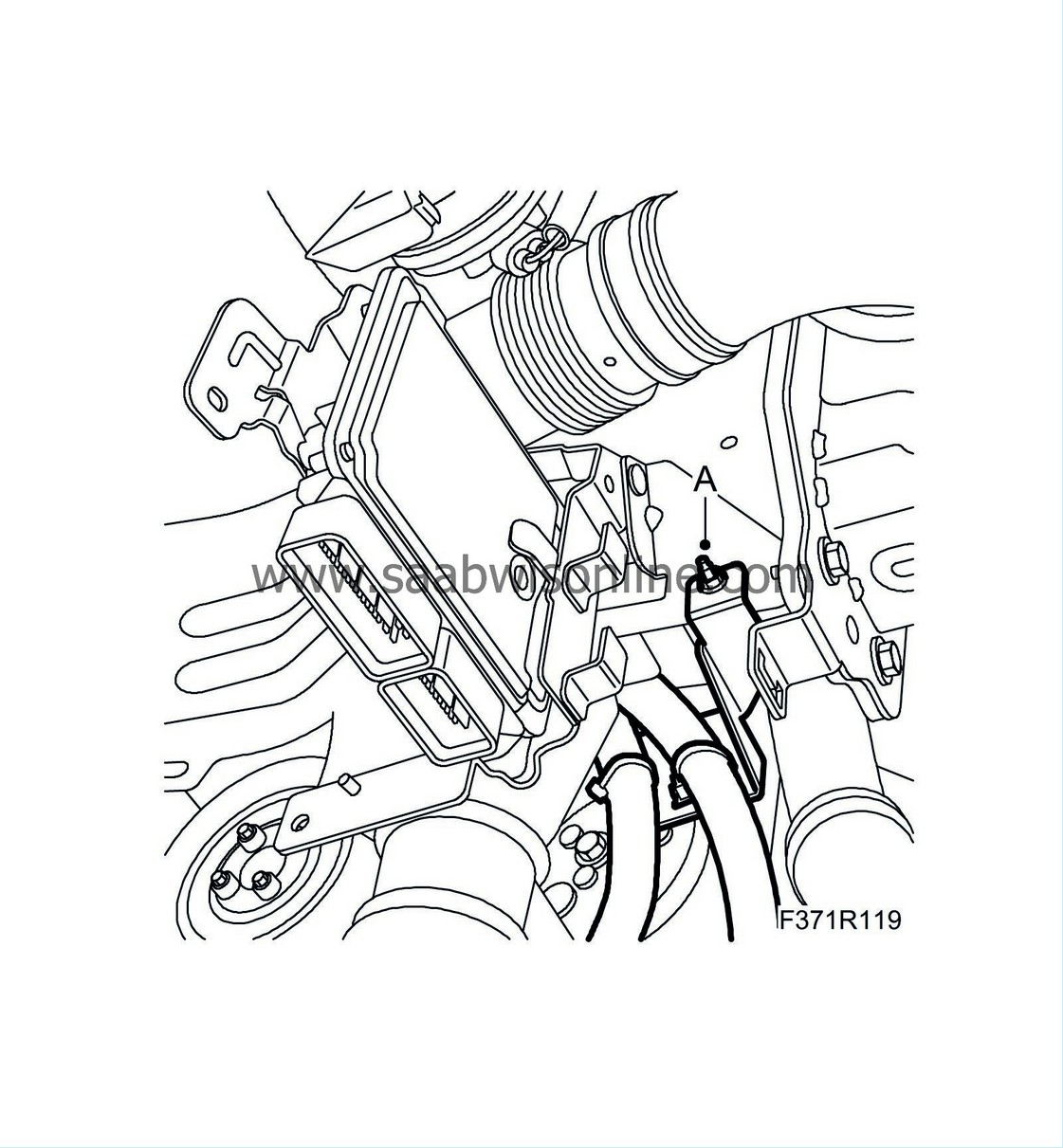
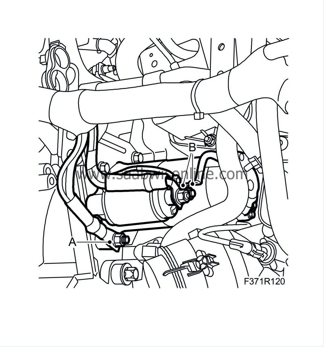
Remove the ground connection (A) on the engine.
|
|
22.
|
Remove the electrical connections (B) from the starter motor.
|
|
23.
|
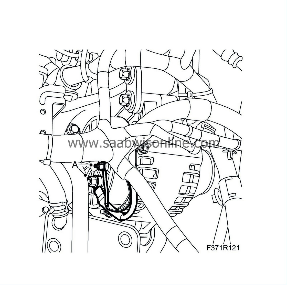
Remove the electrical connections (A) from the generator.
|
|
24.
|
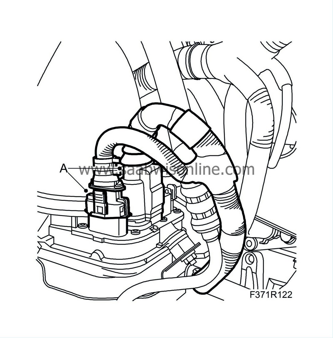
Remove the electrical connections (A) from the power steering pump and the clip holding the wiring.
|
|
1.
|
Position the new wiring in the engine bay and bring down the part to be connected to the control module.
|
|
2.
|
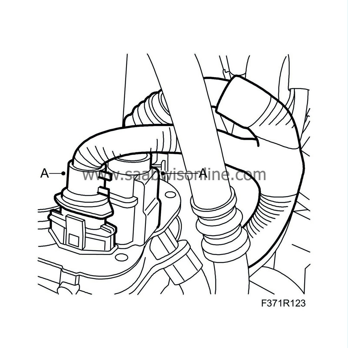
Route the power steering pump wiring between the engine and power steering hose. Fit the clip and plug in the connectors (A) of the power steering pump.
|
|
3.
|
Attach the electrical connections (A) to the generator.
|
|
4.
|
Attach the electrical connections (B) to the starter motor.
|
|
6.
|
Attach the ground connection (A) on the engine.
|
|
7.
|
Fit the bracket (A) protecting the AC compressor wiring.
|
|
8.
|
Fit the right side cover and secure the wiring:
|
|
|
•
|
Fit the right side cover (A).
|
|
|
•
|
Fit the cable tie (B) holding the wiring around the control module.
|
|
|
•
|
Attach the right control module connection (C).
|
|
9.
|
Fit the bumper shell:
|
|
|
•
|
Check that the cellular block sits correctly in the shell.
|
|
|
•
|
Position the bumper. Press the shell rearward and press the shell clips into the holder.
|
|
10.
|
Cars with headlamp washer:
Attach the washer hose.
|
|
11.
|
Fit the lower engine cover (D), the connector (C) and plug in the connector (B). Fit the spoiler shield (A).
|
|
12.
|
Fit the bumper bolts in the wing liner (A).
|
|
14.
|
Fit the upper radiator member clips (A).
|
|
15.
|
Fit the connector (A) on the AC pipe and the clip (B) on the right structural member.
|
|
16.
|
Fit the clips (A) on the right rear structural member and a cable tie (B) to hold the wiring harness together.
|
|
17.
|
Fit the air filter housing:
|
|
|
•
|
Fit the air filter housing (C).
|
|
|
•
|
Attach the hose to the mass air flow sensor (B).
|
|
|
•
|
Plug in the mass air flow sensor connector (A).
|
|
18.
|
Plug in the connectors (A) on the back of the engine.
|
|
19.
|
Plug in the connectors (A) of the pressure sensor for the particle trap and temperature sensor and attach the clip (B) to the water hose.
|
|
20.
|
Fit the clips (A) and cable tie (B) that hold the wiring on the left side and rear of the engine.
|
|
21.
|
Fit the clips (A) and connections (B) of the radiator fans and charge air valve.
|
|
22.
|
Man. gearbox:
Attach the connection of the reversing light switch.
|
|
23.
|
Connect the wiring and fuse box:
|
|
|
•
|
Attach the connector (E) on the structural member.
|
|
|
•
|
Attach the ground connection (D) and hose clip (D) around the wiring on the structural member.
|
|
|
•
|
Plug in the front connector beneath the detached fuse box.
|
|
|
•
|
Fit the front bolt of the fuse box (C).
|
|
|
•
|
Fit the fuse box cover (A).
|
|
24.
|
Fit the battery tray and components:
|
|
|
•
|
Fit the battery tray (E).
|
|
|
•
|
Fit the wiring harness cable tie (D) to the battery tray.
|
|
|
•
|
Fit the fuse holder (C).
|
|
|
•
|
Fit the glow plug relay (B).
|
|
|
•
|
Attach the electrical connection of the bonnet switch (A).
|
|
|
•
|
Position the battery and fit the bolt to the battery's lock lug.
|
|
|
•
|
Connect the positive cable of the battery.
|
|
|
•
|
Connect the positive cable that runs between the fuse box and the positive battery terminal.
|
|
|
•
|
Connect the negative cable of the battery.
|
|
26.
|
Check the fit of the bumper and adjust as necessary.
|


