Differential clutch
| Differential clutch |
| General |
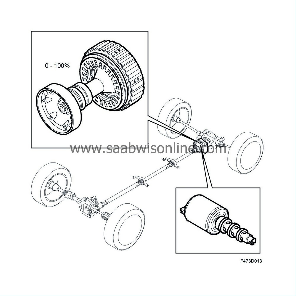
The differential clutch is located in front of the limited slip differential, to which it is bolted. The propeller shaft connects at the front edge to the differential clutch, and then at the rear edge directly to the limited slip differential's pinion via a shaft equipped with splines. The XWD control module is fitted on the housing.
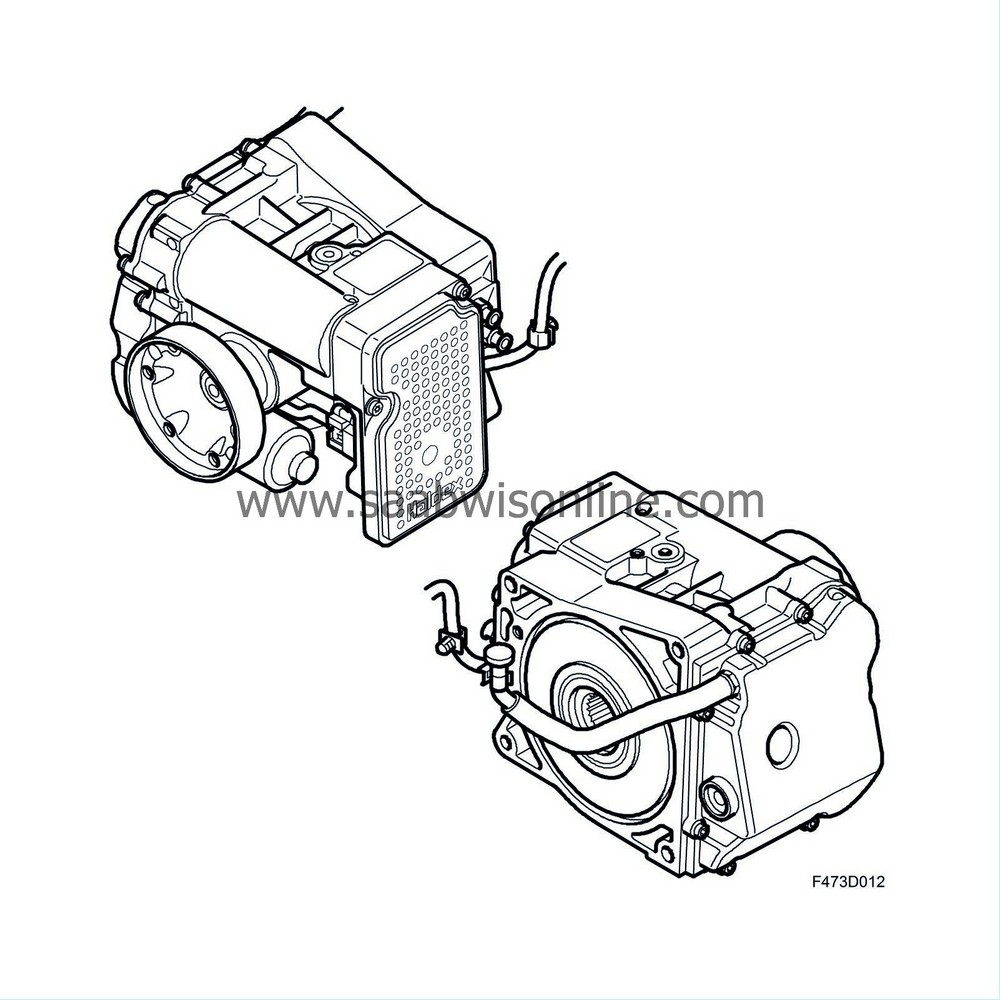
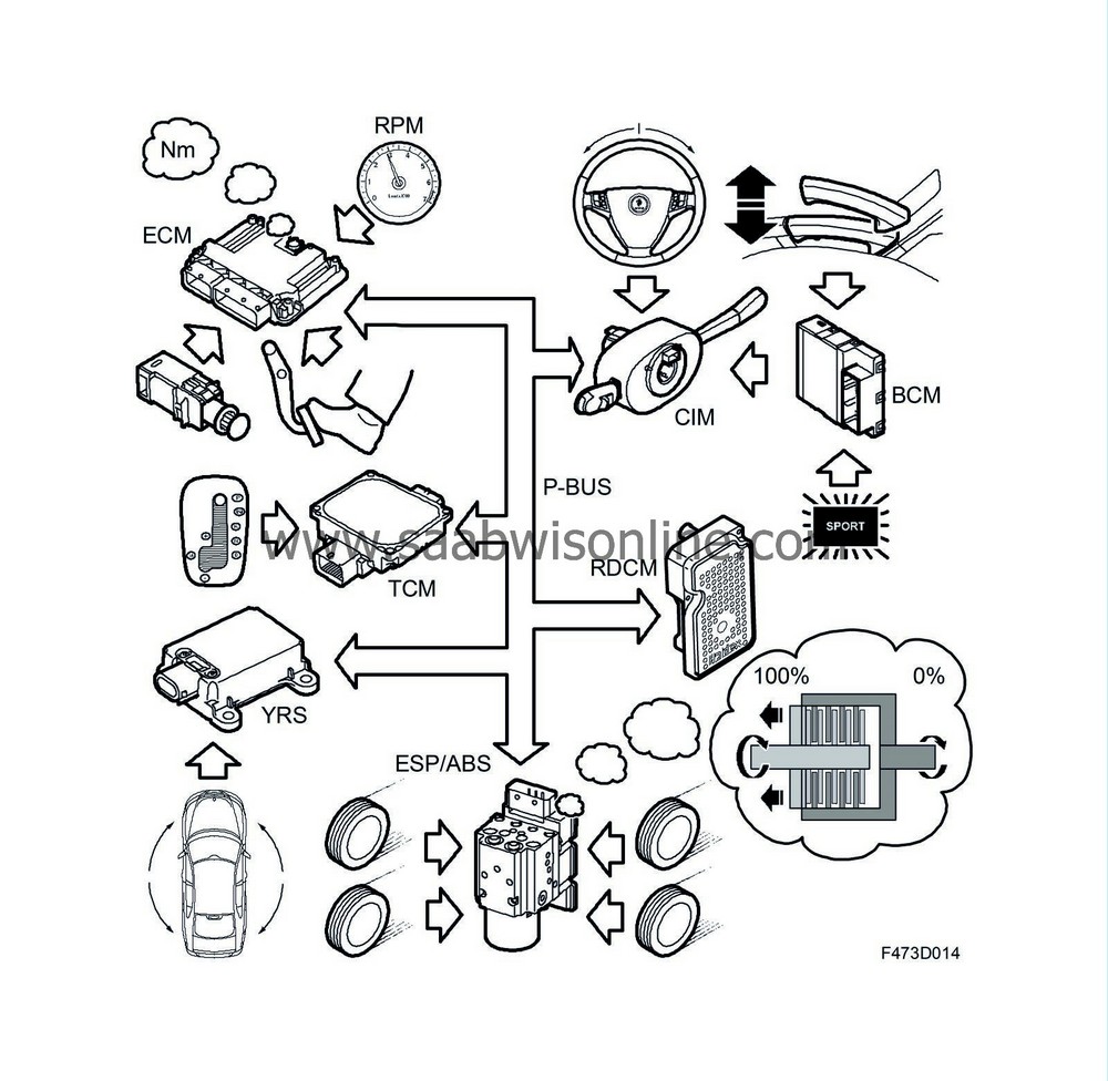
The XWD control module, abbreviated to RDCM, is connected to the vehicle's P-bus and uses information from the following systems:
| • |
ECM:
Requested (accelerator pedal position), current and maximum torque, engine speed, activated brake pedal
|
|
| • |
YRS:
Yaw rate, lateral and longitudinal acceleration
|
|
| • |
ESP:
Wheel speed of the four wheels, XWD disengagement/engagement
|
|
| • |
CIM:
Steering wheel angle
|
|
| • |
TCM:
Current gear
|
|
| • |
BCM:
Handbrake activated, SPORT mode activated.
|
|
These bus messages are used to determine the operating/driving conditions for the vehicle, and accordingly how much drive torque should be transferred to the rear wheels.
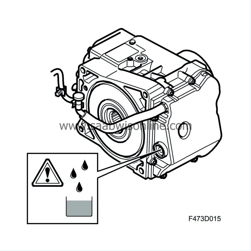
During manufacture the differential clutch is filled with fluid, which then does not require changing. The correct type of fluid must be used without exception when filling. The incorrect type of fluid will destroy the differential clutch.
| Housing |
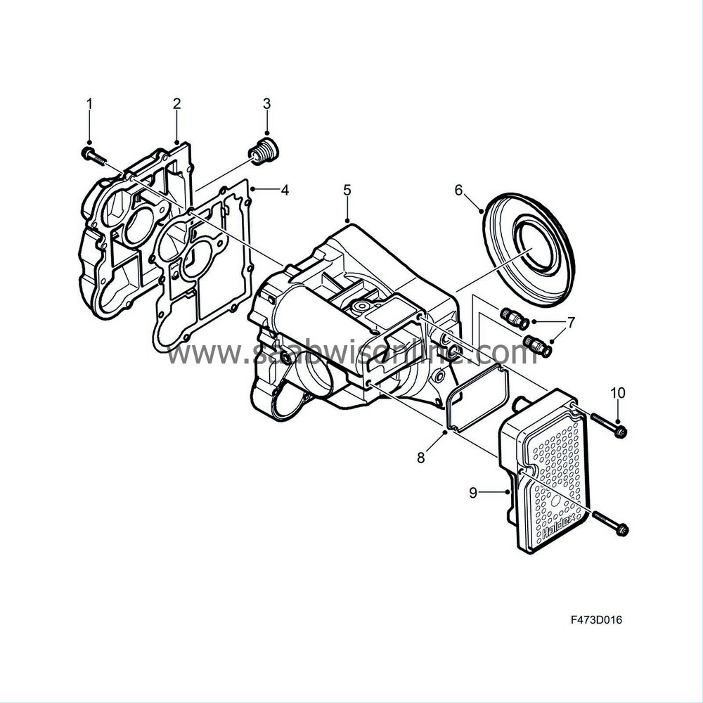
The housing (5) is produced from a pressure-cast aluminium alloy for maximum strength. On the right-hand side of the housing is a cover (2) which partly constitutes the fluid reservoir and is bolted with 10 bolts (1). The mating face is sealed with a thin steel gasket (4) coated with rubber. The oil filler plug (3) is fitted in the cover and it also constitutes the level indicator for the fluid. On the left-hand side of the housing are the fluid connections for the limited slip differential clutch (7) (only applies to vehicles equipped with limited slip differential clutch).
A second cover (rear face) (6) is fitted in the rear edge of the housing to the limited slip differential. This consists of a round steel disc, in the periphery of which is a sealing ring. In the centre of the rear face is a radial seal for sealing the output shaft. The clutch cage's journal bearing rests against the inside of the rear face. The rear face is prevented from being pressed out by means of the differential clutch being bolted to the limited slip differential.
Fitted on the outside of the housing are the pump unit and the XWD control module (9), and the control valve is fitted behind this. Inside are the input shaft, clutch cage with disc pack, operating piston, oil filter, non-return valve, oil accumulator and bearing.
| Input shaft |
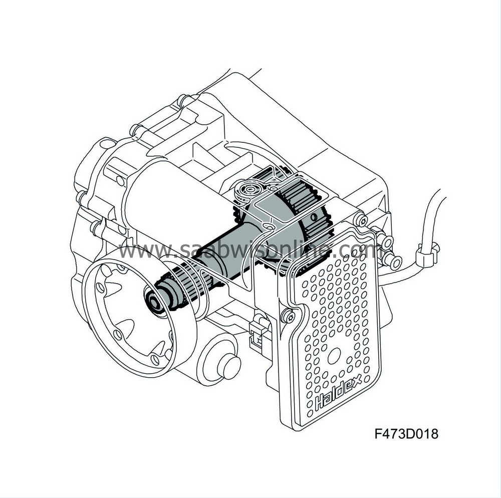
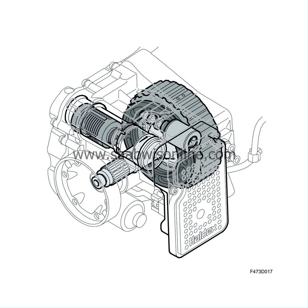
The function of the input shaft is to transfer power from the propeller shaft to the differential clutch disc pack. The front section of the input shaft is equipped with splines and a thread furthest out, to which the driver is attached. The shaft is sealed with a radial seal and is mounted in a single-row groove ball bearing. The other end of the input shaft constitutes the hub for the disc pack. Externally the hub is equipped with bars, into which the driven plates engage. The disc cage's guide bearing is located inside the hub. The bearing is a needle bearing.
The hub is equipped with oil ducts to cool and lubricate the disc pack. They are supplied with fluid from a chamber in front of the hub, which is connected with the fluid reservoir in the right-hand side of the housing. Fluid is led through the ducts to radially positioned holes which direct fluid out into the centre of the disc pack.
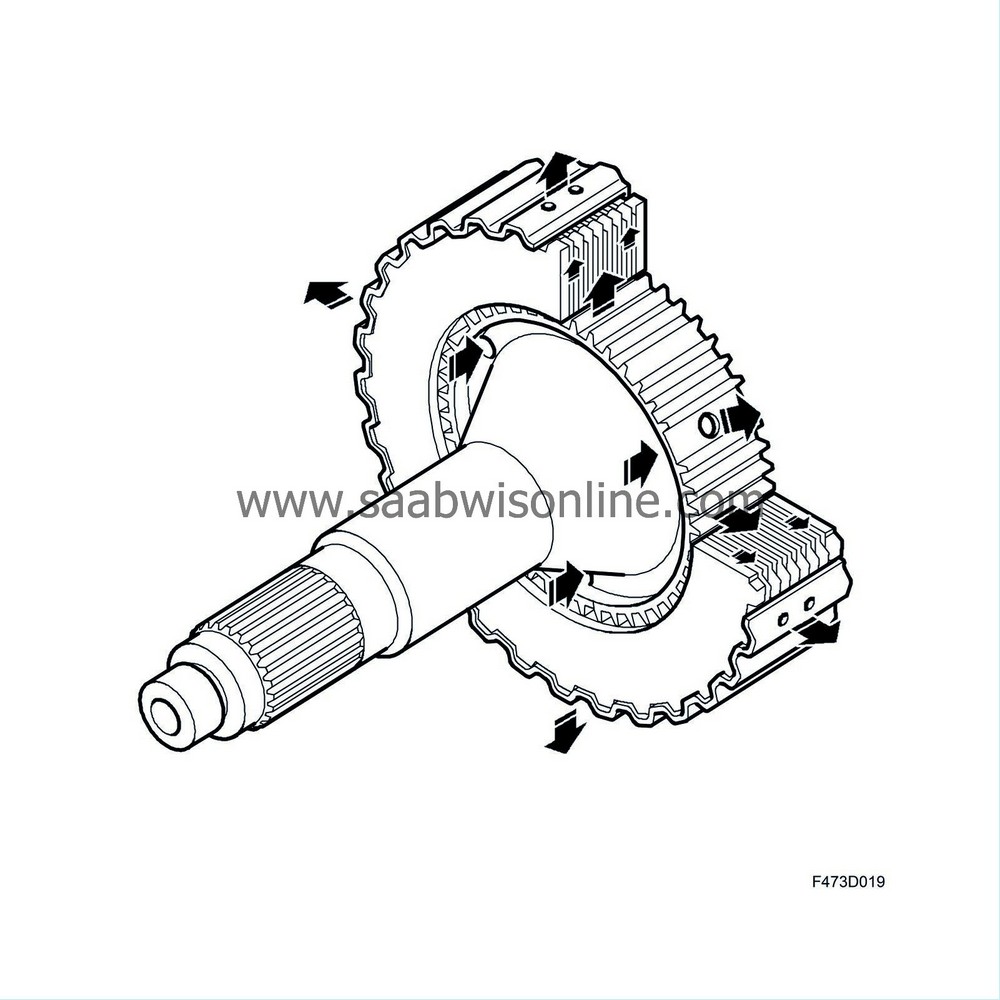
| Disc pack (assembly) |
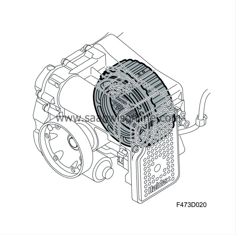
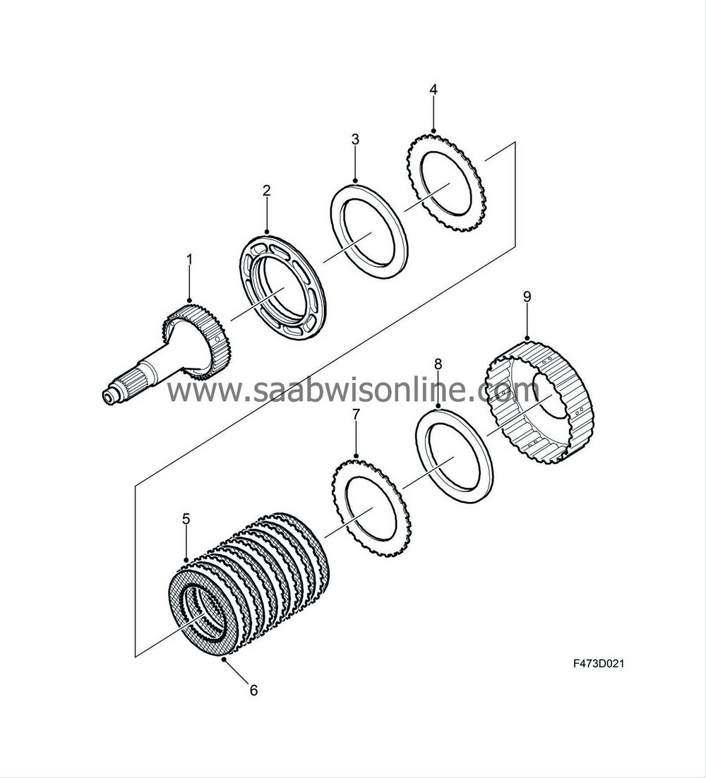
The function of the disc pack (5) is to steplessly (0-100% locking) transfer the required torque to the rear wheels (e.g. limited slip differential). It consists of 8 driven plates (5) driven by the input shaft's hub (1). They are produced in steel and coated with a sintered bronze alloy. The surface of the driven plates has a checked pattern to efficiently distribute and drain off the fluid flowing from the hub. Between the driven plates are 7 smooth steel discs, the periphery of which is serrated and adapted to the drum's bars. Farthest out in the disc pack are steel discs (4, 7) which are considerably thicker, and their function is to distribute the force to the disc pack so that the pressure is evenly distributed. These are also serrated in the periphery which fits in the drum's bars.
The disc pack is compressed by means of an operating piston. Between the operating piston and the disc pack's first steel disc is a thrust bearing which is an integrated part of the operating piston. The thrust bearing is a radial needle bearing. Between the rear of the drum and the rear face is a journal bearing which is an integrated part of the drum. The journal bearing is a radial needle bearing. The rear face is prevented from being pressed out by means of the differential clutch being bolted to the final drive gear housing.
The drum is produced in pressed steel plate, its centre is produced in steel and is laser welded to the drum. Its walls have drainage holes for the fluid that has passed through the disc pack. The fluid is thrown out against the walls by the rotation of the drum and is led back to the fluid reservoir on the right-hand side of the housing.
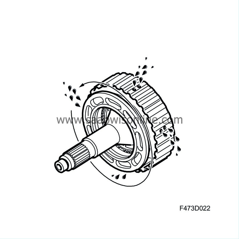
There is a chamber in the housing and cover for the differential clutch which acts as a reservoir for the fluid. The reservoir is divided into two volumes, one for activating the hydraulic circuit and one for the disc pack's cooling fluid. A limited exchange of fluid takes place between these two reservoirs. The limited slip differential has a pin equipped with splines which fits into the centre of the drum.
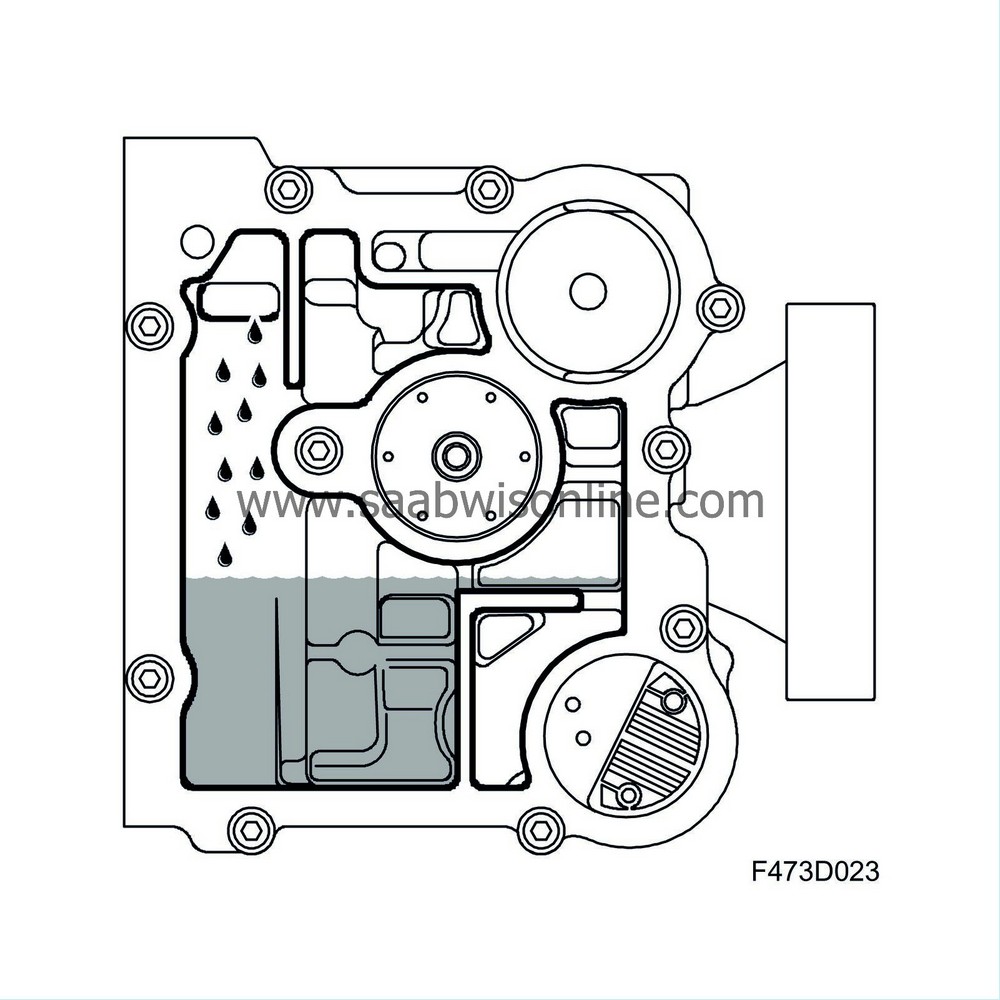
| Hydraulic pump |
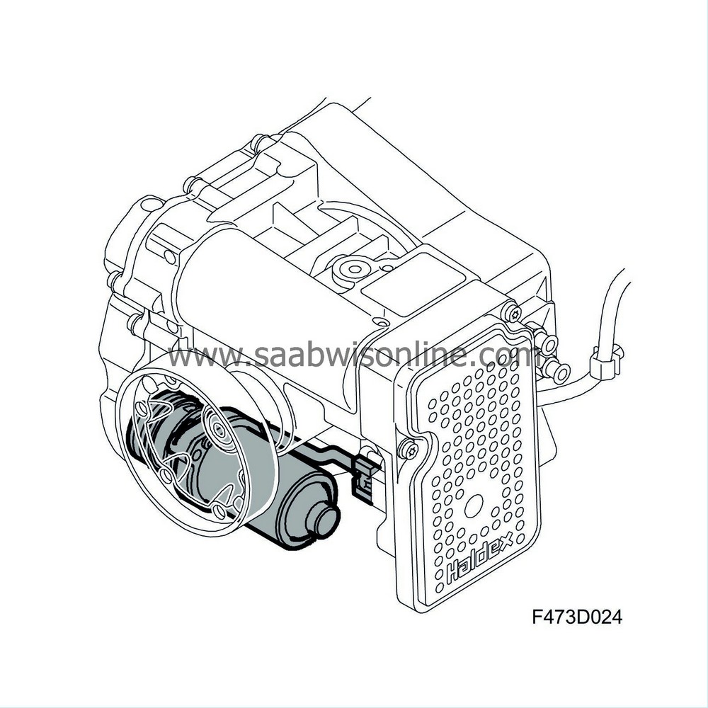
The function of the hydraulic pump is to create the oil pressure required for actuating the operating piston, as well as the limited slip differential clutch if fitted. The oil pressure is normally 27-32 bar.
The hydraulic pump consists of an electric motor of permanent magnet type and a pump housing. It is supplied with power from the XWD control module.
| 1. |
Retaining bolt
|
|
| 2. |
Engine
|
|
| 3. |
O-rings
|
|
| 4. |
Thrust bearing
|
|
| 5. |
Swing plate
|
|
| 6. |
Pistons with return springs
|
|
| 7. |
Cylinder block
|
|
| 8. |
Strainer
|
|
| 9. |
Pump plate
|
|
| 10. |
Oil filter
|
|
| 11. |
Retaining bolts
|
|
| 12. |
Electrical connection
|
|
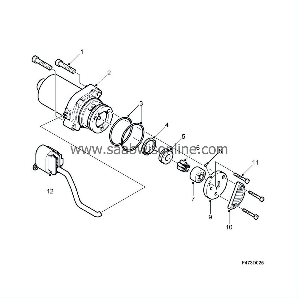
The motor drives a five cylinder axial piston pump in the pump housing. The seal between motor shaft and pump housing is by means of a radial seal. The motor's shaft drives a rotating cylindrical block, in which five holes are drilled. They form cylinders for the pump pistons. The holes are drilled parallel with the shaft.
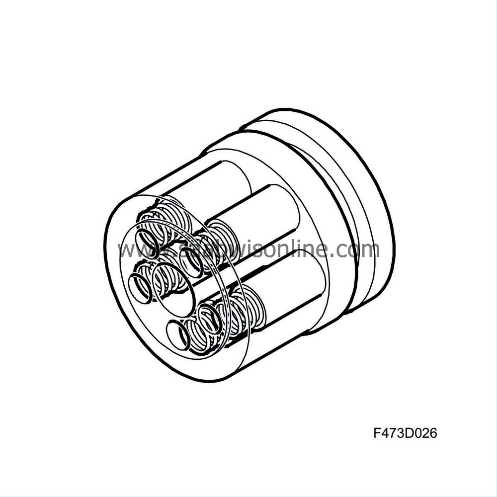
The pistons are given an axial movement backwards in the cylinder, i.e. during the process when the pump element draws oil, by means of each cylinder's return spring. The forward movement, when the pump is supplying oil, is by means of the rear edge of the pistons being pressed against a so-called swing plate in the pump housing. The swing plate is on the same centre axis as the cylinder block, but they are at a certain angle in relation to each other. There is a ball bearing type thrust bearing between swing plate and cylinder block.
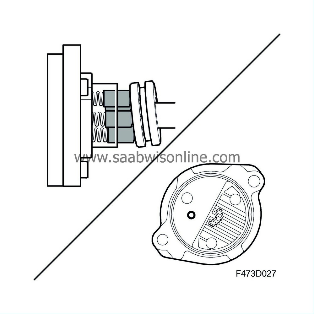
The end plate of the hydraulic pump consists of the pump plate. This is equipped with two grooves, one throughout through which the pump draws oil from the reservoir via a fine-mesh sieve which prevents particles which could damage the pump from being drawn in. There is a duct to the pump housing from the second groove from which the pressurised oil then proceeds out via the oil filter in the torque converter housing. The pump housing is sealed externally to the differential clutch housing with two O-rings. The inner one is fitted between the pressure side and the suction side, the outer one between the pressure side and outside of the differential clutch housing.
The pump starts as soon as the following conditions are fulfilled:
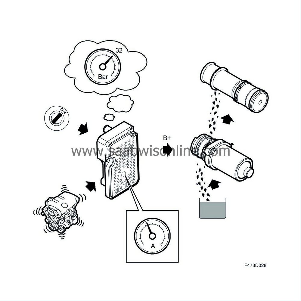
| • |
Ignition ON
|
|
| • |
Vehicle engine has started
|
|
It pumps until the calculated hydraulic pressure in the accumulator is approx. 32 bar (filled accumulator), or until the condition is not fulfilled. The control module measures the pump current and when the current is constant this in an indication that the pressure is not increasing any further. The accumulator is accordingly filled and the pump is switched off. When the calculated hydraulic pressure in the accumulator is less than approx. 27 bar the pump starts again.
| Oil filter |
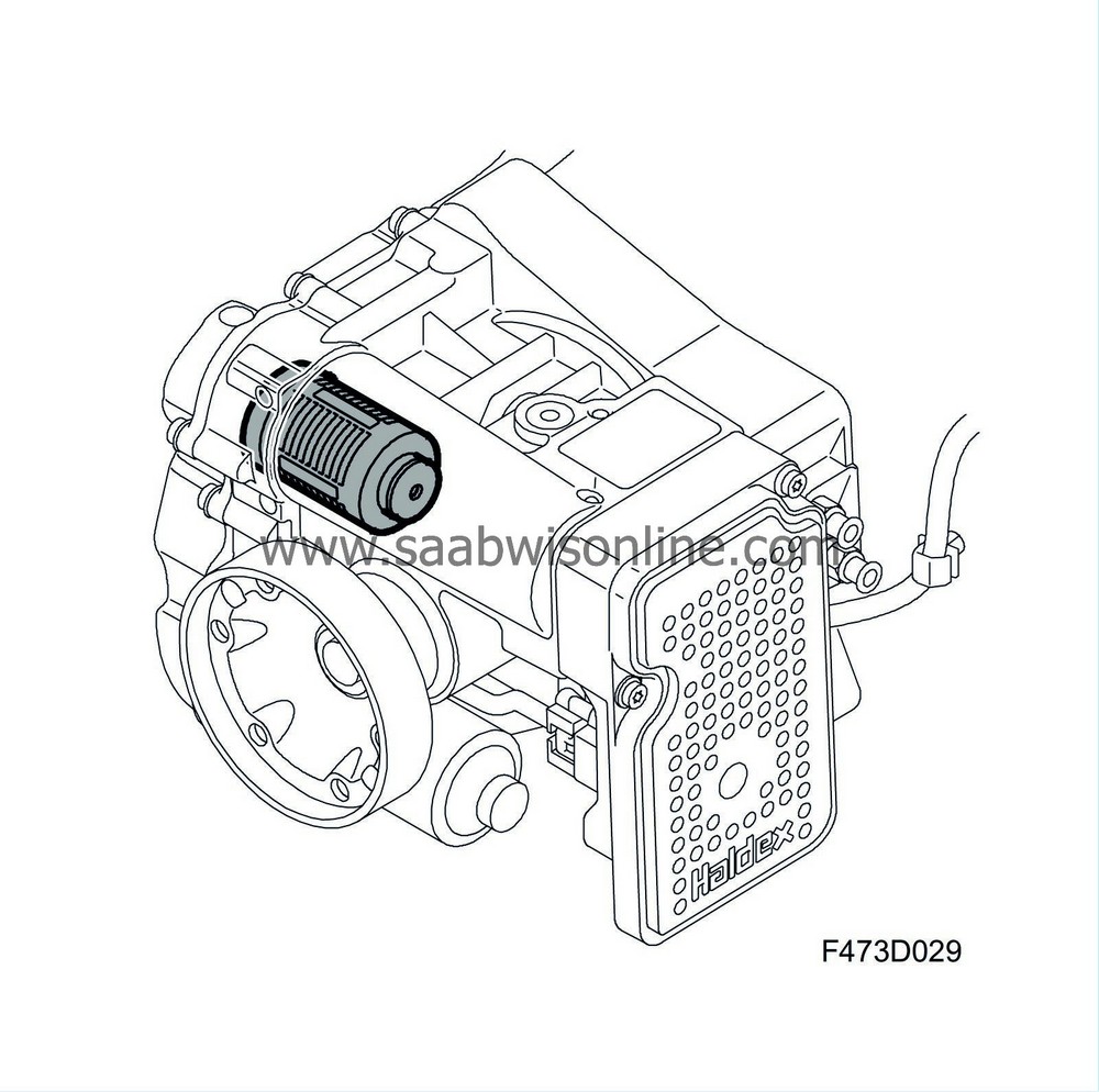
The function of the oil filter is to separate fixed impurities in the hydraulic circuit oil after it has passed the hydraulic pump. The filter is located inside the differential clutch housing, the filter can be replaced by removing the cover on the right-hand side of the housing.
It consists of a cylindrical plastic housing in which the filter medium is located. The oil flow through the filter is from the inside and out. One end plate of the filter is equipped with a cylindrical connection which fits in the differential clutch housing. It is pressed in and held in place by means of the opposite end plate supporting against the cover on the differential clutch. The connection is sealed with an O-ring.
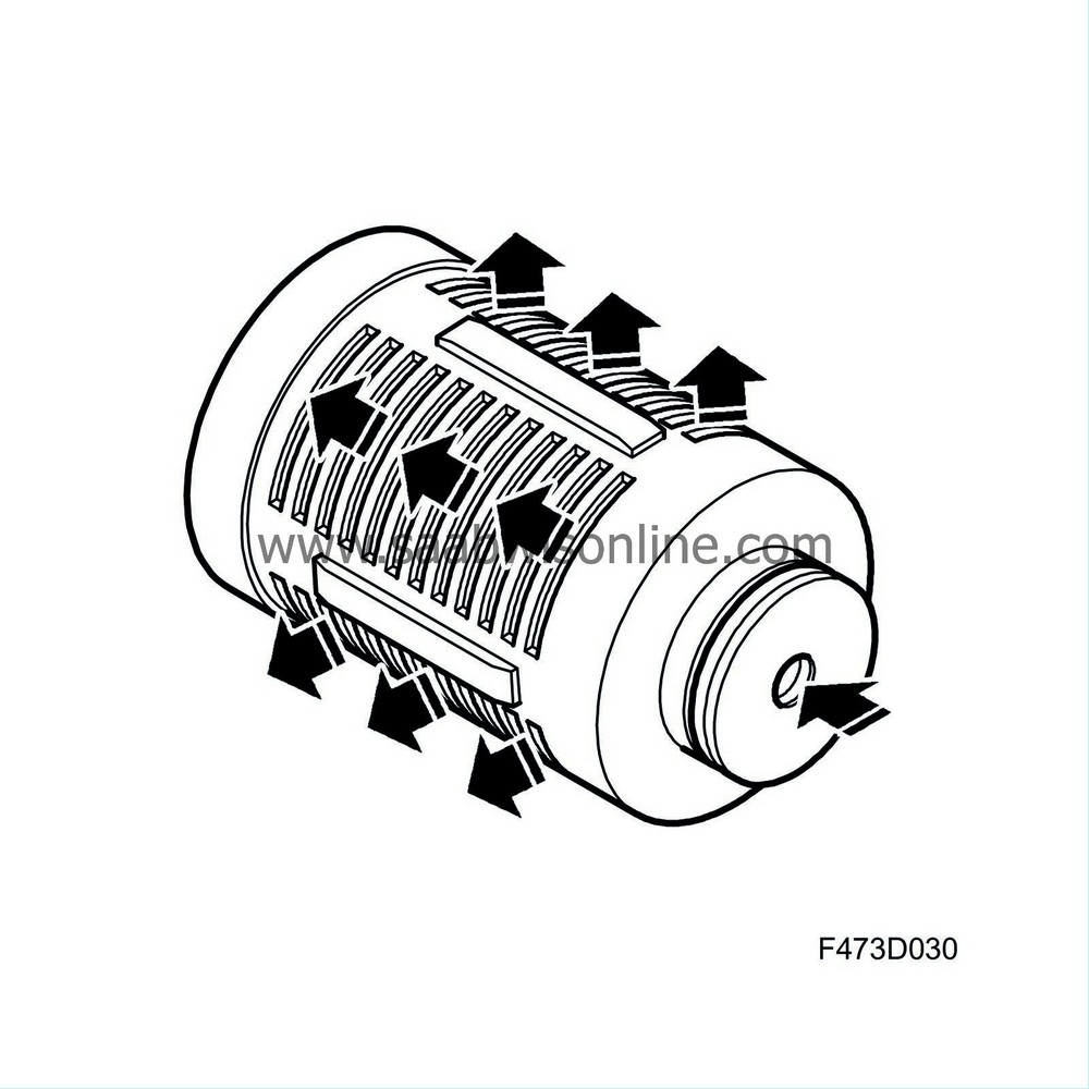
The oil is led into the centre of the filter via a non-return valve. This prevents the pressurised oil in the accumulator from leaking out via the pump when it is not operating. Otherwise this would lead to a loss of pressure.
| Pressure accumulator |
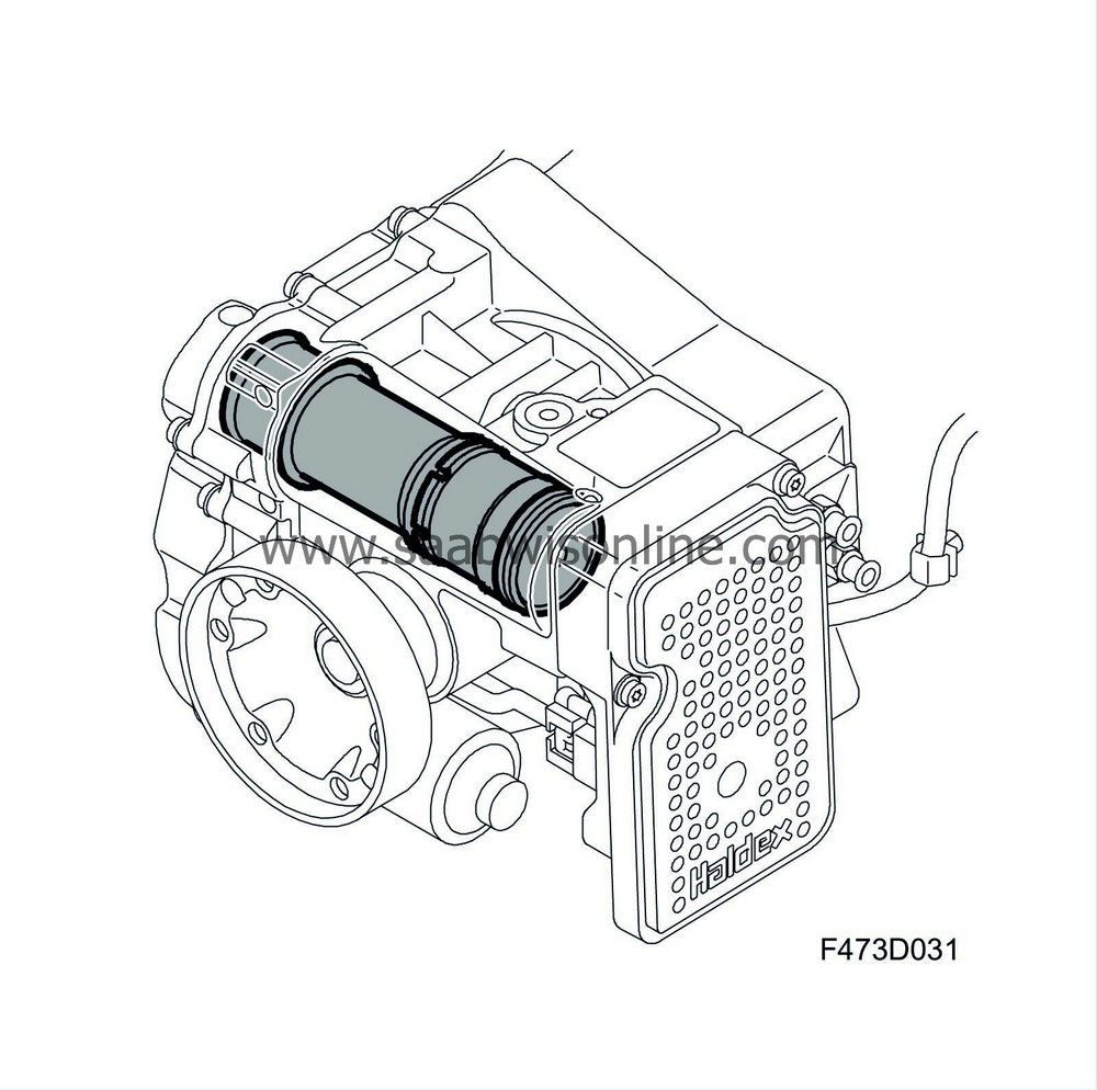
The function of the pressure accumulator is to store a volume of oil under pressure in order that the XWD system shall have a rapid response time, and so that the electric motor does not need to operate the whole time.
It is fitted in the differential clutch housing and must not be removed.
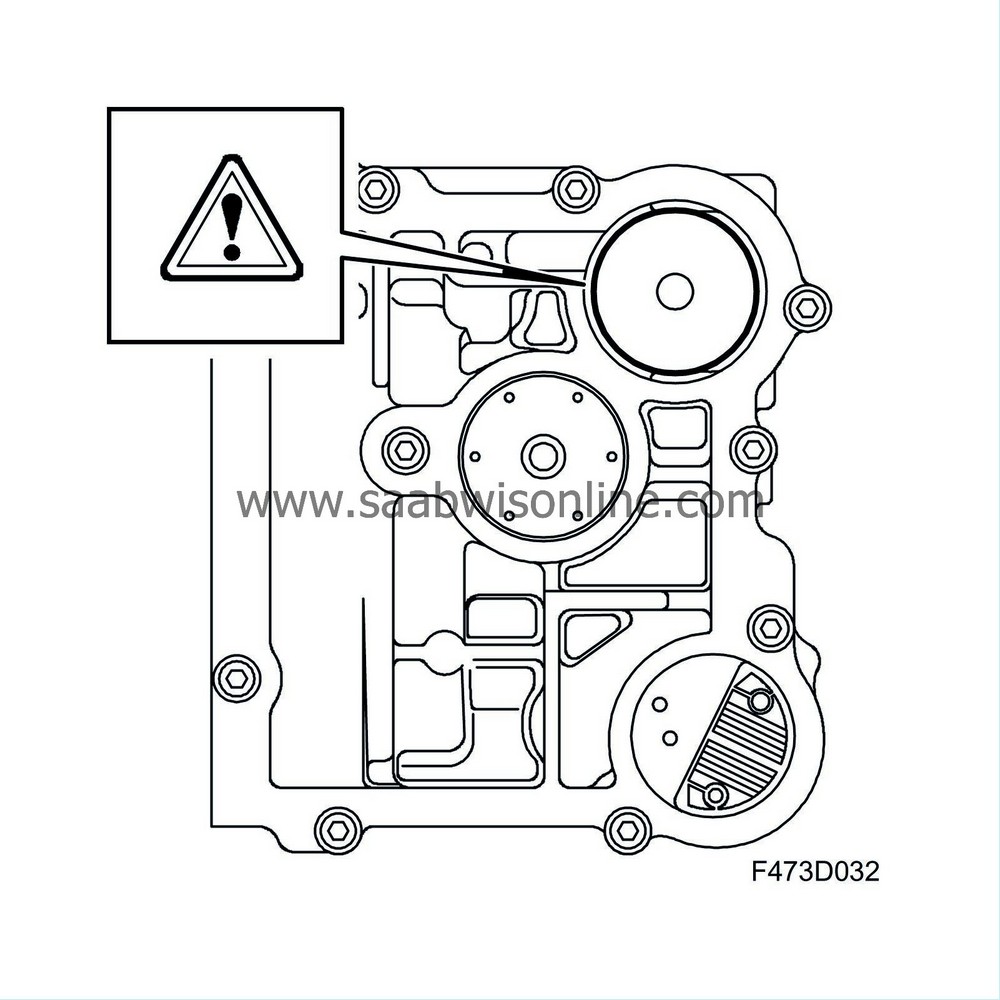
The accumulator is the piston accumulator type and consists of a piston, piston sleeve, spring sleeve and three pressure springs. The springs are tensioned so that an oil pressure of 27 bar is required for the accumulator piston to start moving. At a pressure of approx. 32 bar the piston exposes the unloading holes in the piston sleeve and the pressure cannot increase further.
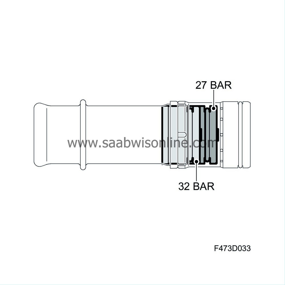
The accumulator piston is produced in steel and has a diameter of 34.5 mm. It is equipped with a groove in which there is a sealing ring fitted. The piston runs in a piston sleeve "cylinder". The piston sleeve is externally equipped with a seal in the form of an O-ring which seals against the differential clutch housing. The sleeve is equipped with a number of radially positioned unloading holes. When the piston's sealing ring has passed the unloading holes the oil in the accumulator will flow out through them and onward to the differential clutch oil reservoir. This takes place at an oil pressure of approx. 32 bar.
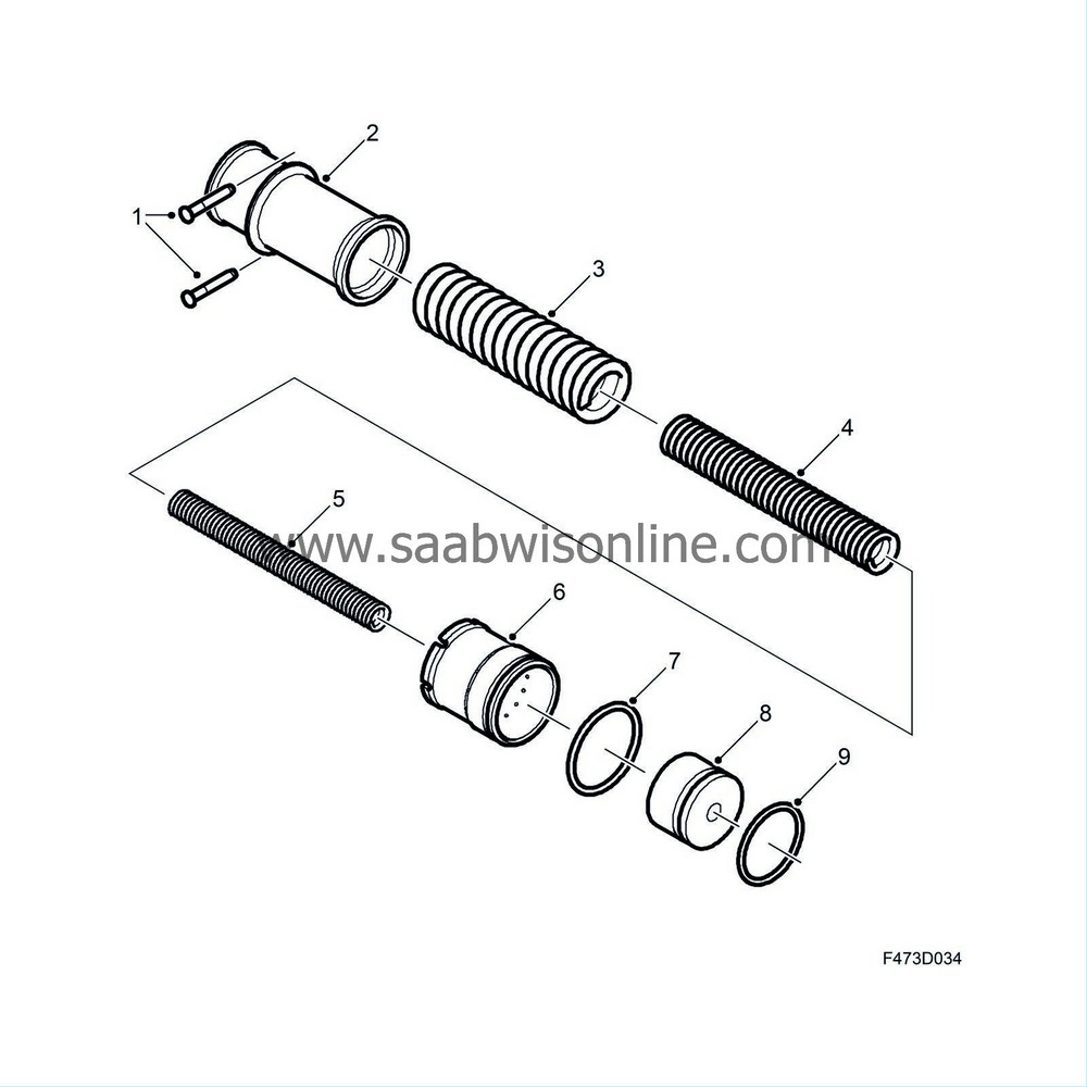
Three pressure springs (3, 4, 5) of different coarseness and length act against the rear side of the piston (8). The combination of the springs' properties means that the accumulator stores a relatively large volume of oil while the oil pressure is held relatively constant. A spring sleeve (2) encloses the spring assembly and also constitutes a support for the springs. A collar (2) on the sleeve together with two pins (1) form the locking for the accumulator in the differential clutch housing.
| Operating piston (ring piston) |
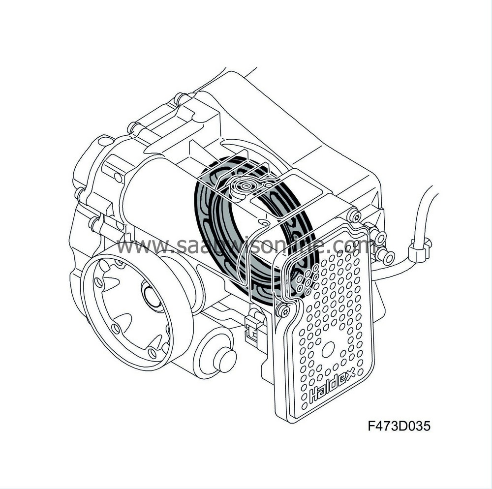
The function of the operating piston is to convert the hydraulic pressure into the force that applies the differential clutch disc pack. It is located in the differential clutch housing, the piston cylinder is formed from the differential clutch housing itself. A variable oil pressure (0-30 bar) acts on the rear side of the piston via the pressure control valve which is controlled by the XWD control module.
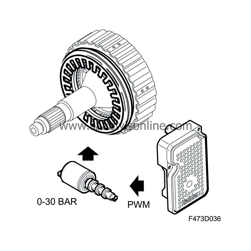
The operating piston is ring shaped and produced from an aluminium alloy. The piston is equipped with grooves internally and externally, in each of which is a sealing ring. A disc spring is fitted on the rear of the piston to provide preload and to absorb excess play in the thrust bearing, disc pack and journal bearing. A thrust bearing is integrated with the piston on the side turned toward the disc pack. The bearing is the needle bearing type.
| Pressure control valve |
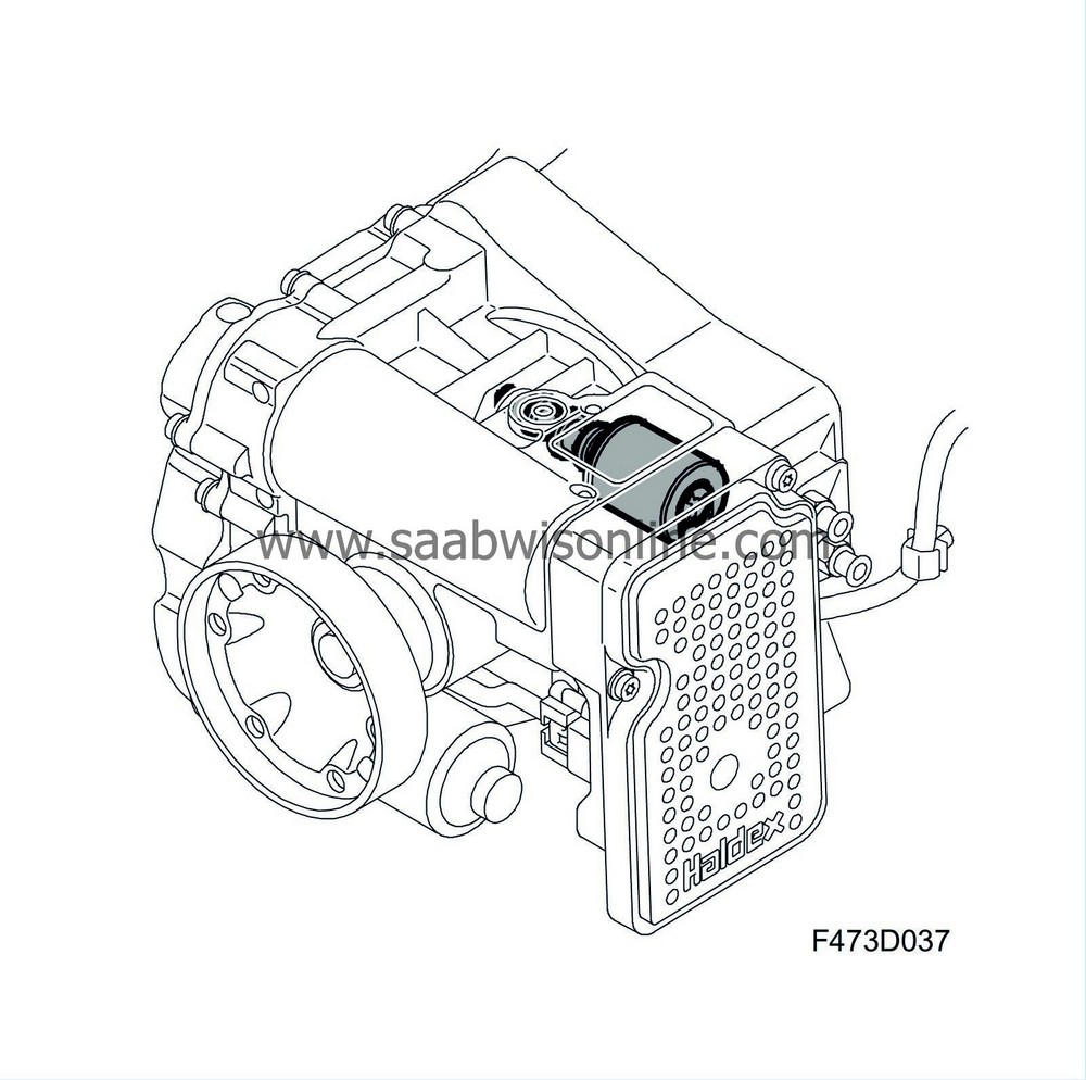
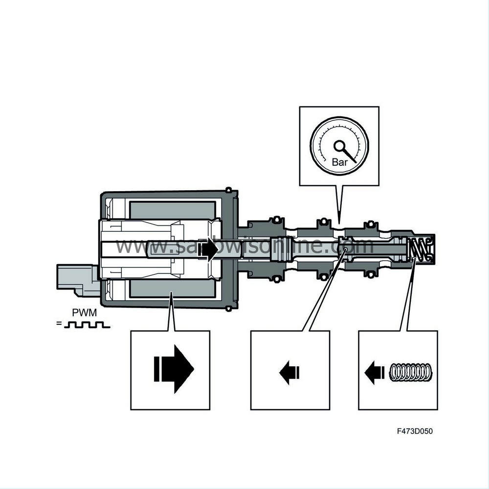
The pressure control valve is electrically controlled and its function is to regulate the hydraulic pressure (0-30 bar) to the operating piston. At which, the driven plates are applied with the equivalent force. In this way the torque transferred to the rear wheels can be regulated. It is fitted in the differential clutch housing, from the outside, behind the XWD control module. The valve is directly connected to the XWD control module which supplies it with a PWM voltage. Its average current will result in a certain given pressure out from the valve. The higher the current (high PWM value), the higher the pressure from the valve.
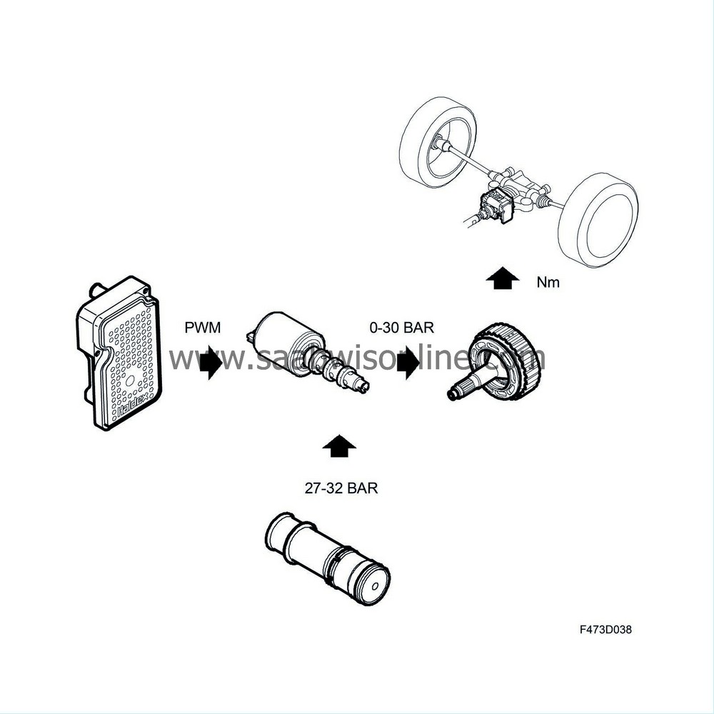
The pressure control valve mainly consists of a cylindrical valve housing in which the valve slide runs, as well as a magnetic coil in which a plunger moves depending on how high a current moves through the magnetic coil.
| 1. |
Oil inlet port
|
|
| 2. |
Oil outlet port
|
|
| 3. |
Oil discharge port
|
|
| 4. |
Return spring
|
|
| 5. |
Support plug
|
|
| 6. |
Rod
|
|
| 7. |
Plunger
|
|
| 8. |
Magnetic coil
|
|
| 9. |
Electrical connection
|
|
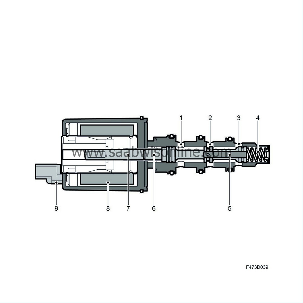
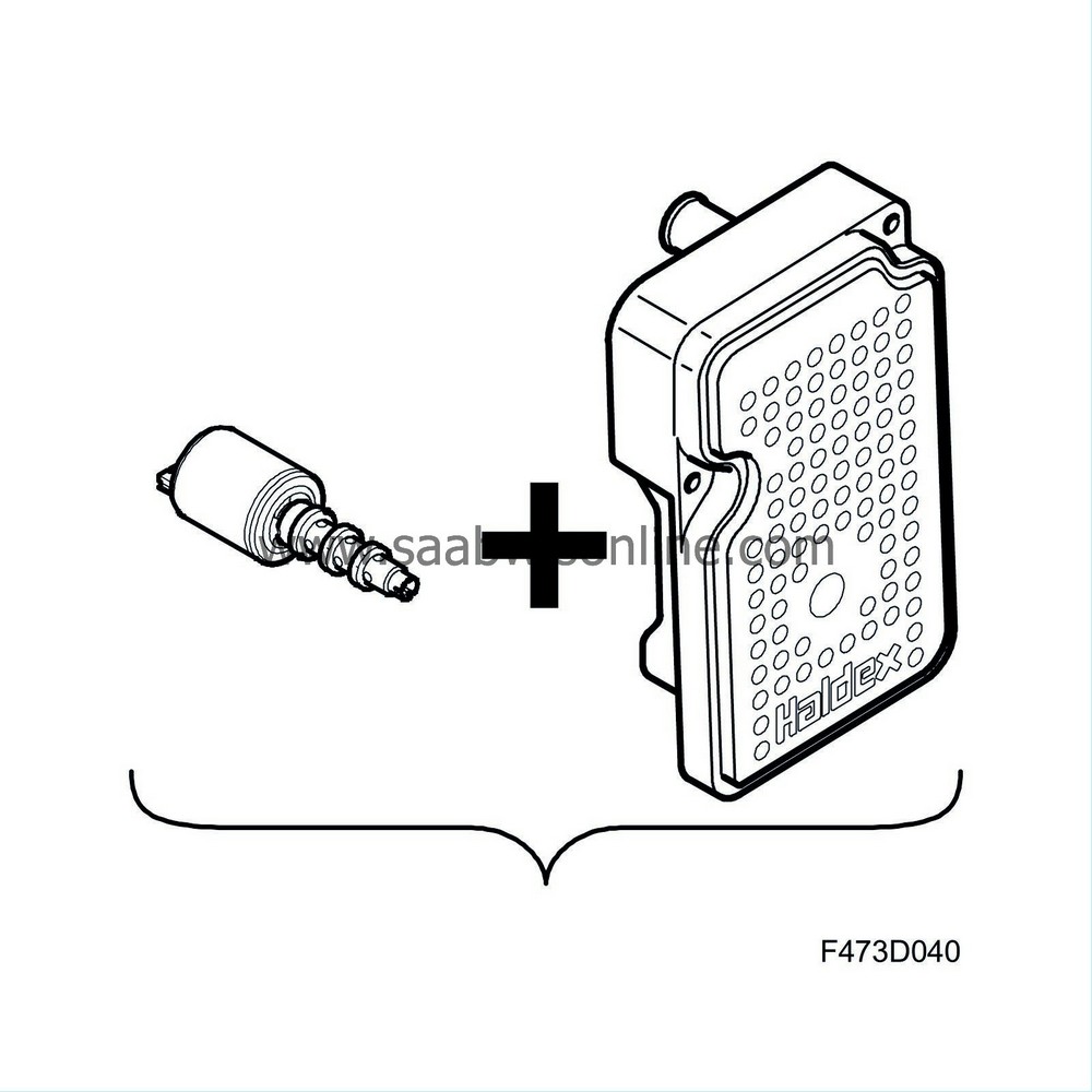
The valve is precisely calibrated together with the XWD control module, they must be replaced together without exception. Otherwise the pressure calculated by the XWD control module, and with it the torque transferred, will not correspond.
The valve housing is cylindrical and produced in steel, and externally is equipped with three O-rings to seal against the differential clutch housing. It is equipped with three valve ports, closest to the magnetic actuator inlet, in the centre of the outlet (regulated pressure to the operating piston) and furthest out, the discharge port to the oil reservoir. In its far end is a plug that provides support for the rod running in the valve slide and for the return spring.
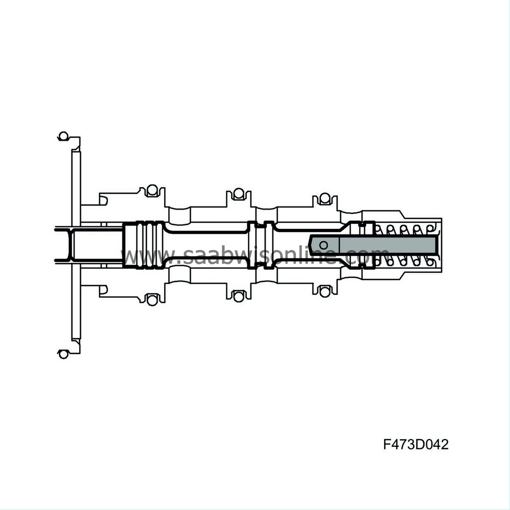
The valve slide runs inside the valve housing, and is produced in steel, within narrow tolerances. The slide has three valve pistons where the centre one constitutes the control valve itself. The slide is drilled out from the far end to the valve piston in the centre. A rod runs inside which supports against the valve housing end plug.
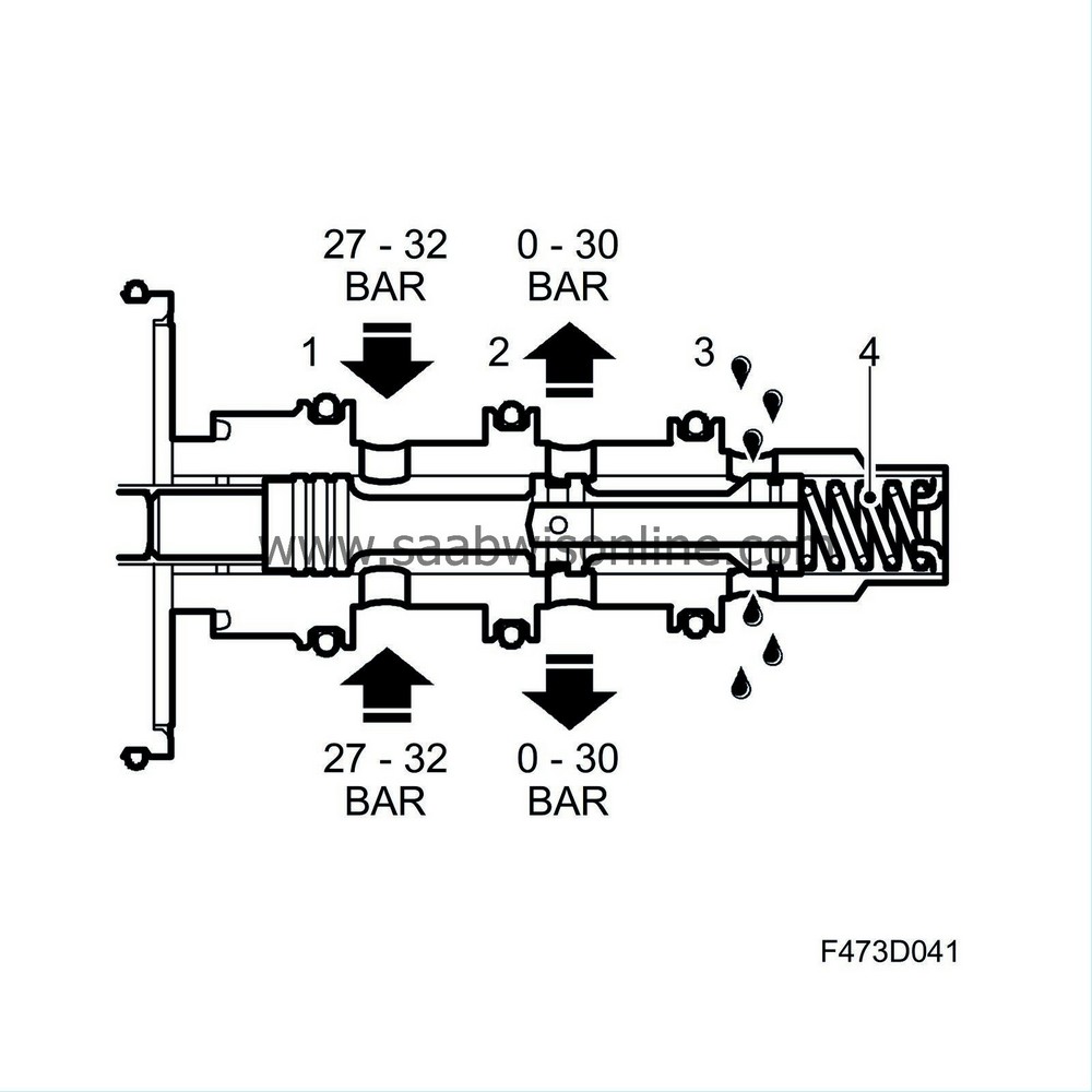
Oil under pressure is led into the pressure control valve's input chamber via the inlet port, where the oil pressure acts against two equally large areas on the valve slide. Its position, and consequently its control characteristics, are accordingly independent of oil pressure. An equally large force that attempts to open the valve attempts to close it. In de-energised status the valve is held closed by the force of the return spring.
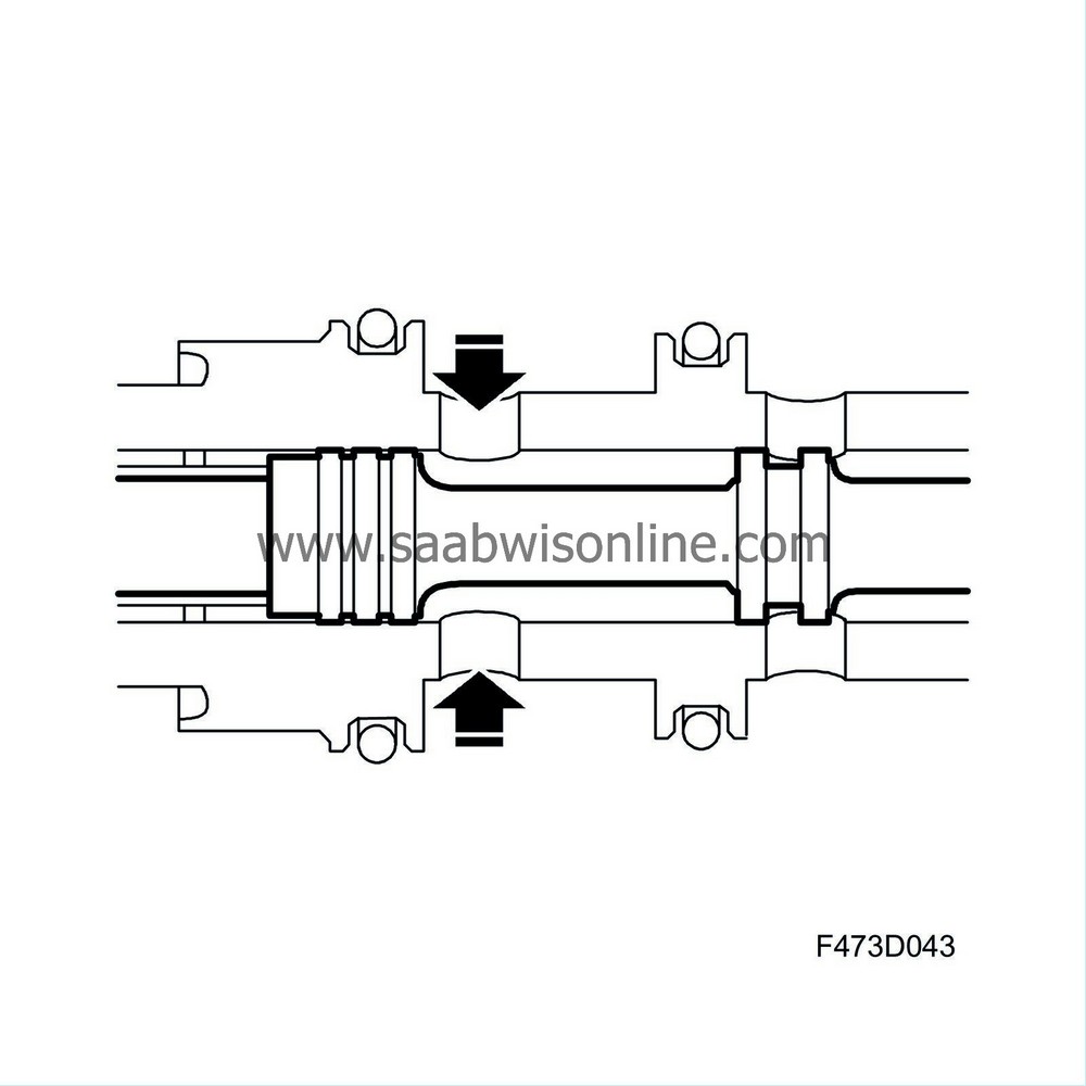
When a current flows through the magnetic coil the valve slide is acted on by a force that is dependent on the strength of the current through the coil. The force causes the valve slide to move in opening direction. A passage between input chamber and output chamber is now opened. Oil flows out from the valve's outlet port to the differential clutch operating piston and the pressure increases, also in the chamber inside the valve slide, in the control chamber.
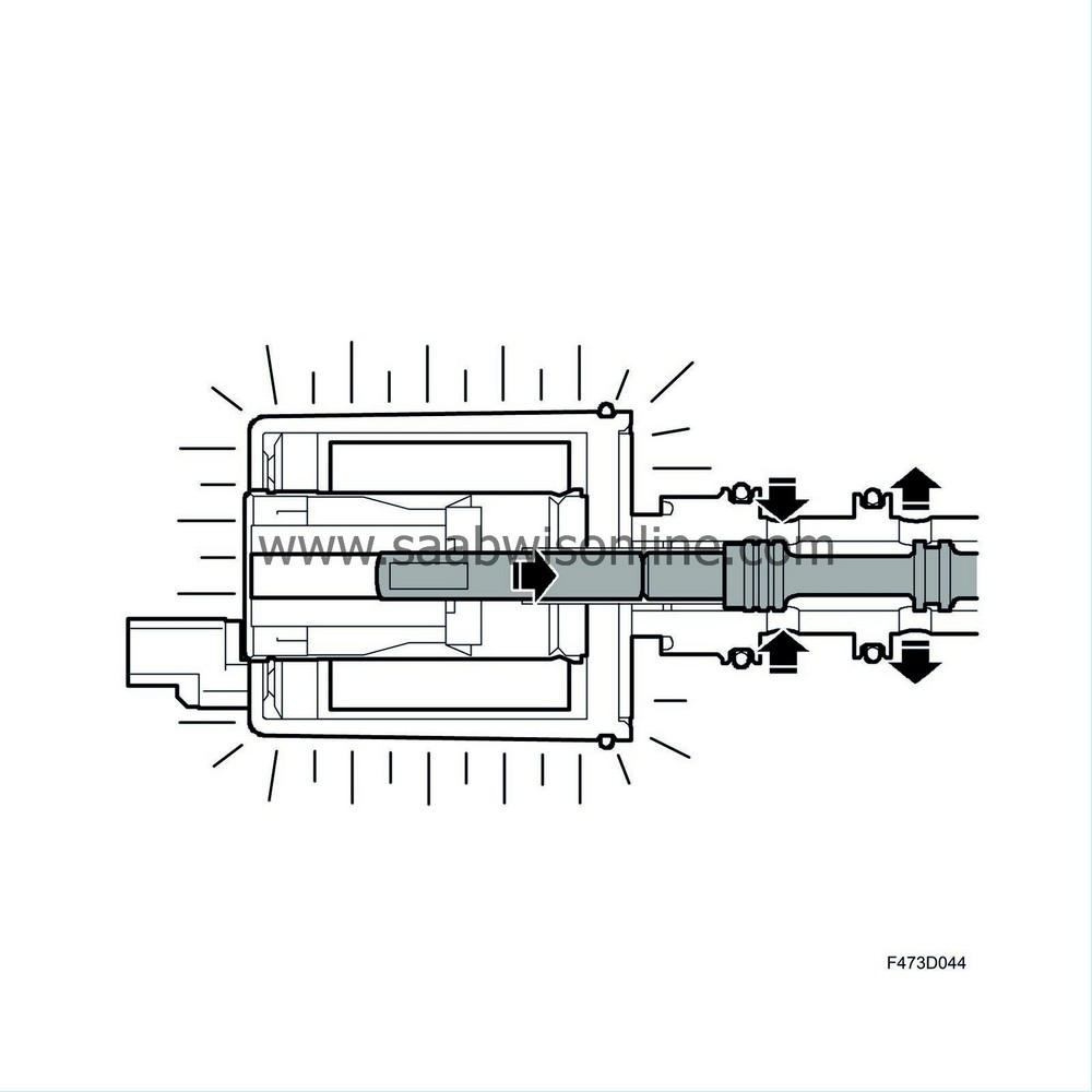
The oil in this chamber will act on two surfaces of equal area. One surface is formed by the rod, the force from the oil presses the rod against the valve housing end plug, consequently this force does not affect the position of the slide. The other surface is formed by an equally large surface as the rod inside the valve slide, the force from the oil presses the side towards closing direction. The higher the oil pressure the stronger the hydraulic force which, together with the return spring, attempts to close the valve.
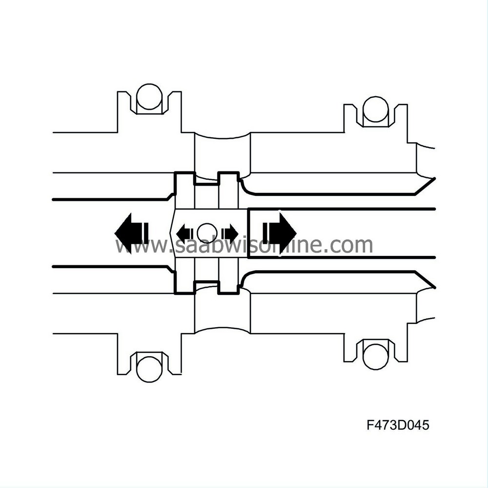
The relationship between the force of the return spring, the force from the oil pressure in the control chamber, and the force from the magnetic coil give the valve slide a state of equilibrium so that a constant pressure of oil to the operating piston is obtained. In this state of equilibrium the output port is separated from the valve's input chamber where there is oil under high pressure and from the return chamber which is depressurised. The pressure in the oil led to the operating piston acts on the position of the slide by means of the pressure in the control chamber.
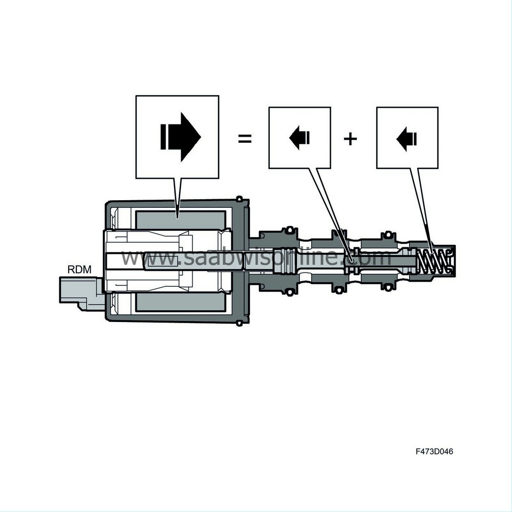
In the state of equilibrium the force from the return spring + the force from the control chamber = the force from the magnetic coil.
A reduction of working pressure (oil pressure from the control valve) means that the force in closing direction decreases, the slide opens the passage between the input chamber and the output chamber, the pressure of the oil in the output chamber increases and a new state of equilibrium comes into force.
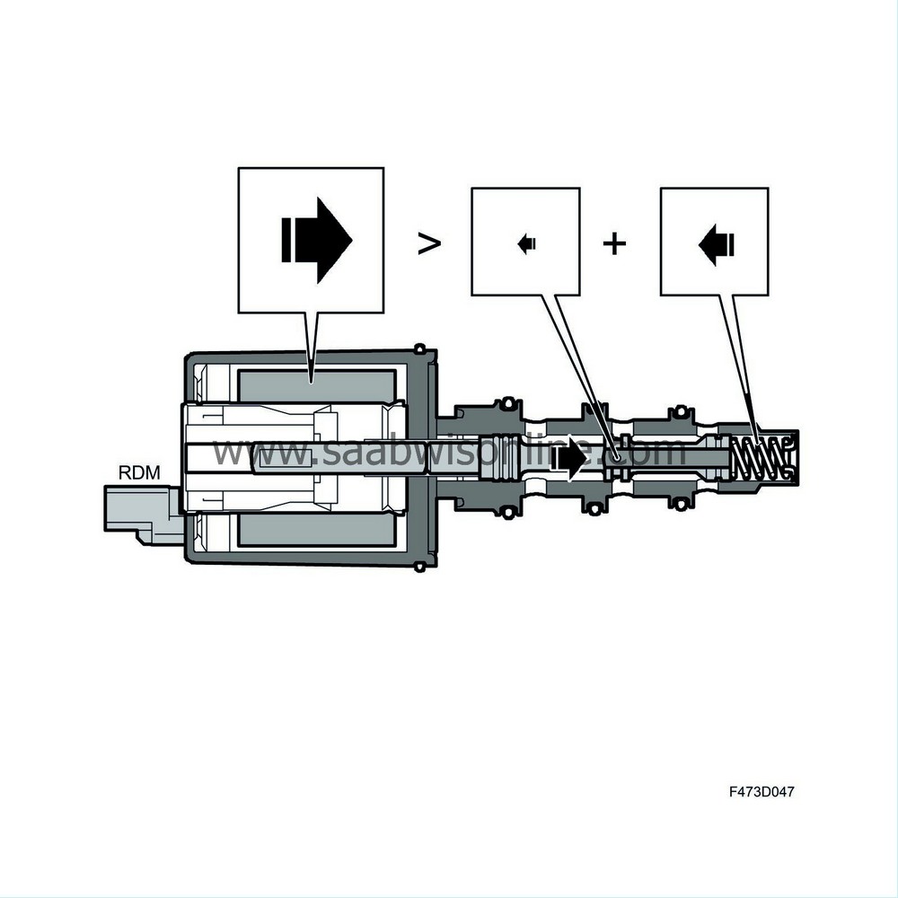
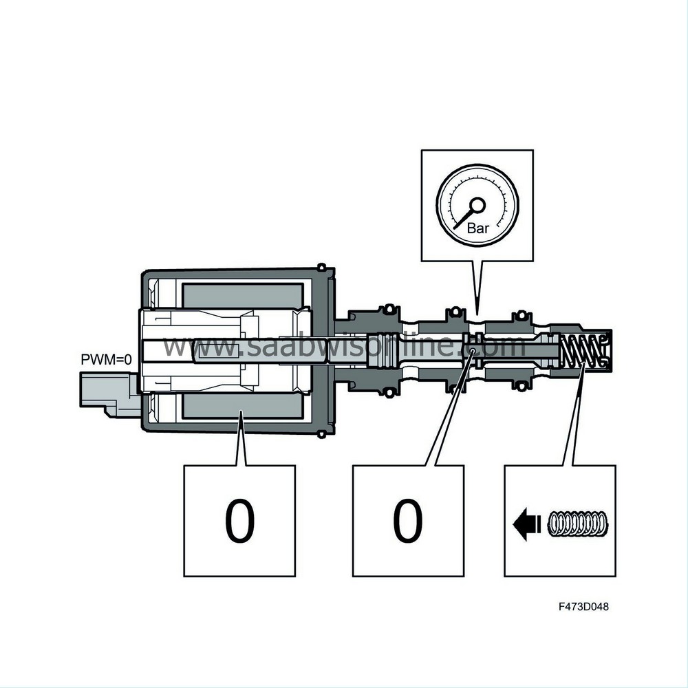
Example:
De-energised . The pressure from the valve is zero, the force from the magnetic coil that acts in opening direction is zero. The force from the control chamber that acts in closing direction is zero. The force of the return spring is constant and holds the valve closed.
Low current . The pressure from the valve is low, the force from the magnetic coil that acts in opening direction is low. The force from the control chamber that acts in closing direction is low. The force of the return spring is constant.
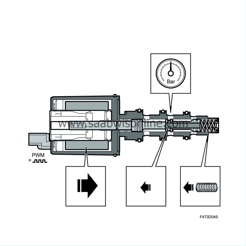
High current . The pressure from the valve is high, the force from the magnetic coil that acts in opening direction is high. The force from the control chamber that acts in closing direction is high. The force of the return spring is constant.
