
Test readings TCS (382)/ESP (671)
| Test readings TCS (382)/ESP (671) |
| Scope |
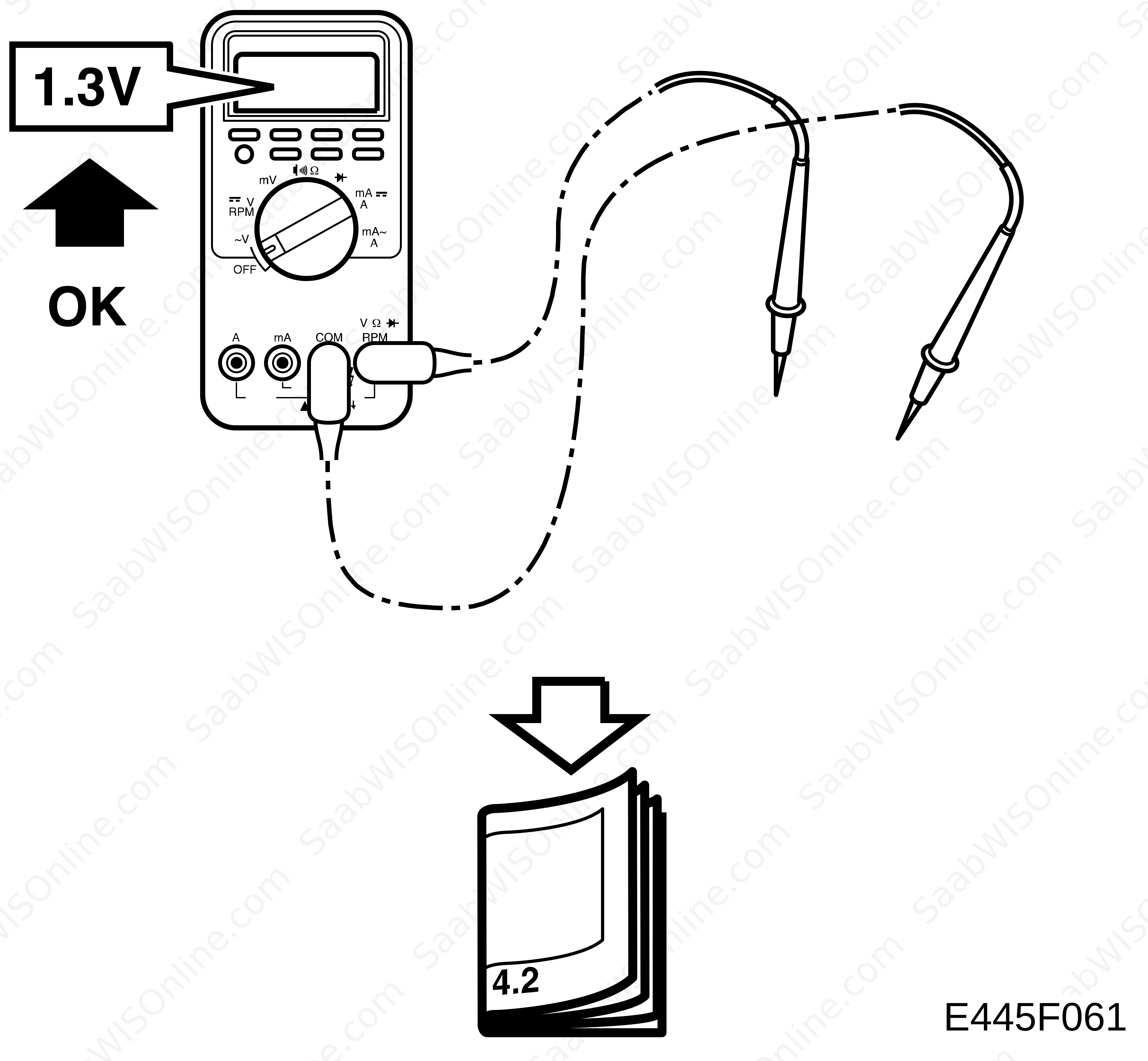
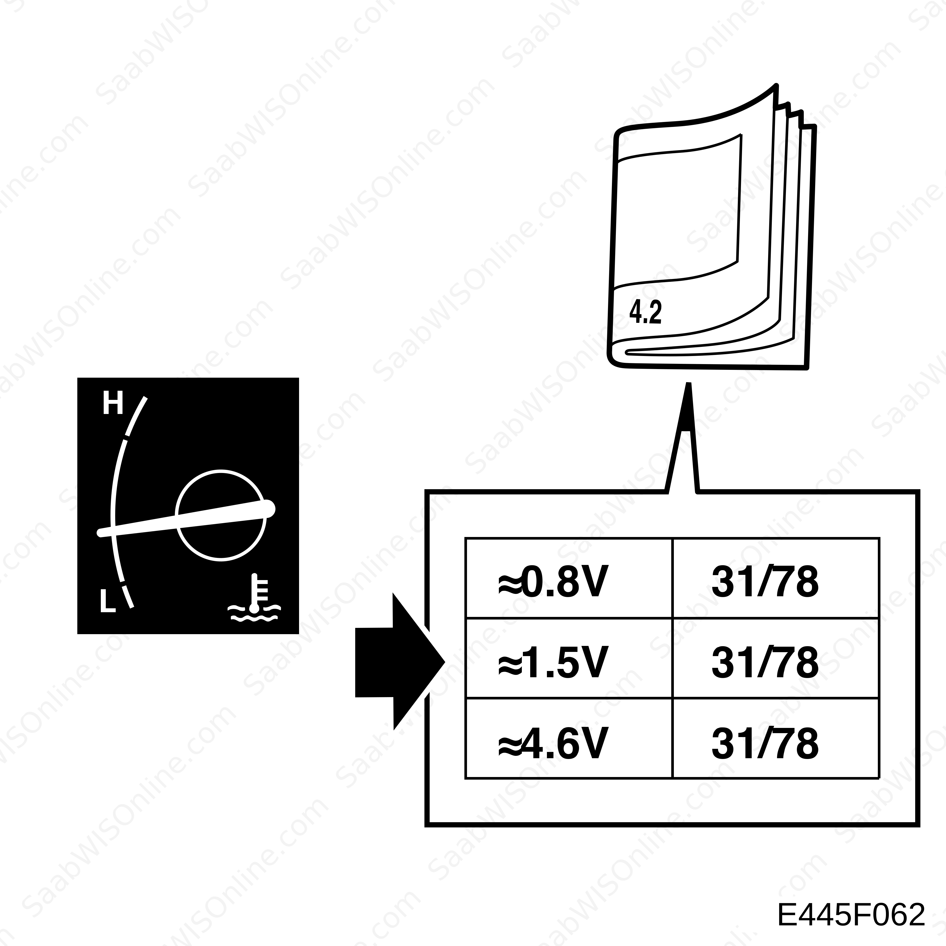
Following are readings and directions for measuring signals and levels of the transmission control module. Pin numbers missing in the table are not used.
| Remember |
| • |
Observe the test criteria and use common sense when assessing the test results.
|
|
| • |
The test reading presented here are with the ignition ON unless stated otherwise.
|
|
| • |
Check first that the control module is receiving power and is grounded.
|
|
| • |
Then check all the sensor inputs and signals from other systems.
|
|
| • |
Finally, check the control module outputs. Remember that test values do not confirm whether the actuator is in working order.
|
|
| • |
If any of the test readings is incorrect, use the wiring diagram to locate the leads, connectors or components that should be checked further.
|
|
| • |
Specified test readings are for a calibrated Fluke 88/97.
|
|
| • |
Test readings %(+) and ms(+) show the signal pulse ratio and pulse width respectively. A scan tool that can measure pulse ratio and pulse width respectively must be used. The sign indicates a positive trigger pulse, TRIG+.
|
|
| Connecting and test readings |
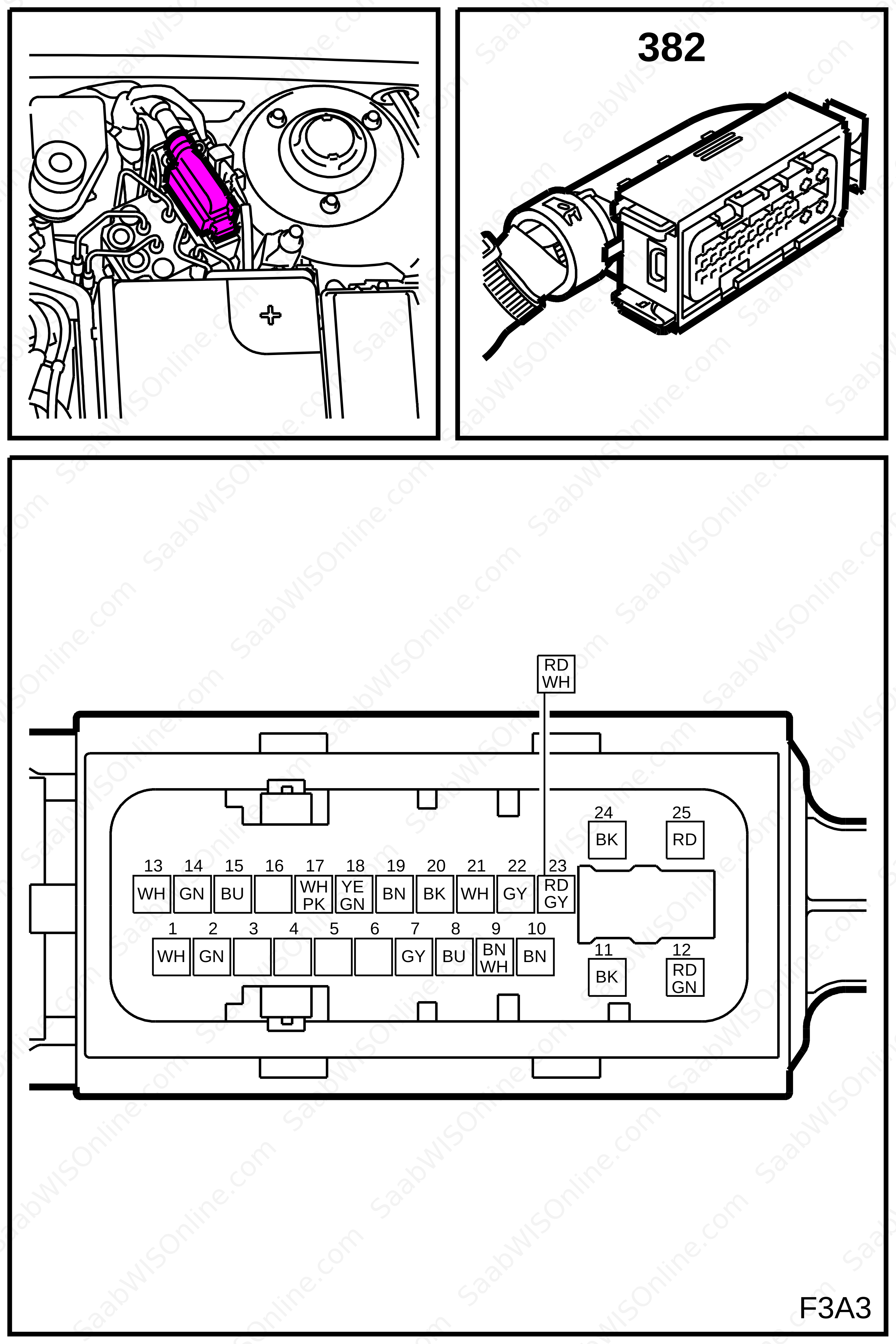
TCS (382)
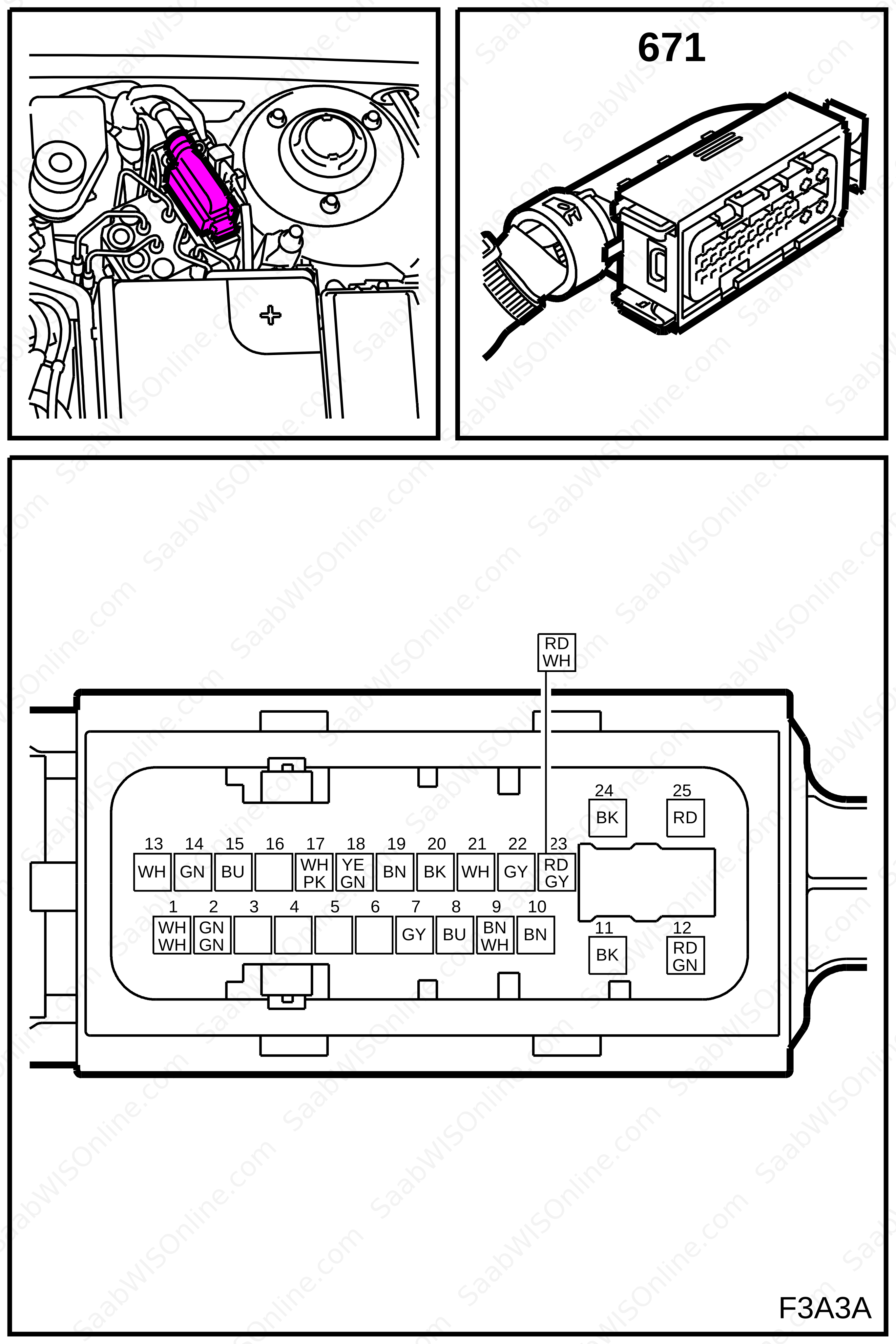
ESP (671)
| Note | ||
|
All units on the I and P buses send signals. |
| Pin, connector A | Component/Function | In/Out | Test criteria | Test across | Test reading |
| 1 | P-bus | In/Out | 1-2 | 2-3 V | |
| 2 | P-bus | In/Out | 2-1 | 2-3 V | |
| 3 | Not connected | ||||
| 4 | Not connected | ||||
| 5 | Not connected | ||||
| 6 | Not connected | ||||
| 7 | Front right wheel sensor signal input | In | Rotate wheel 1 rev per second | 7-8 | >200 mV AC |
| 8 | Front right wheel sensor reference ground | In | Rotate wheel 1 rev per second | 8-7 | >200 mV AC |
| 9 | Rear right wheel sensor signal input | In | Rotate wheel 1 rev per second | 9-10 | >200 mV AC |
| 10 | Rear right wheel sensor reference ground | In | Rotate wheel 1 rev per second | 10-9 | >200 mV AC |
| 11 | Ground, logic | In | 11-12 | B+ | |
| 12 | +30 voltage, logic | In | 12-11 | B+ | |
| 13 | P-bus | In/Out | 13-14 | 2-3V | |
| 14 | P-bus | In/Out | 14-13 | 2-3V | |
| 15 | +X | In | 15-B- | B+ | |
| 16 | Not connected | ||||
| 17 | Brake-light switch | Brake pedal inactive | 17-B+ | B+ | |
| Brake pedal active | 17-B+ | <0.5V | |||
| 18 | Vehicle speed signal to CIM | Out | |||
| 19 | Front left wheel sensor signal input | Rotate wheel 1 rev per second | 19-20 | >200 mV AC | |
| 20 | Front left wheel sensor reference ground | Rotate wheel 1 rev per second | 20-19 | >200 mV AC | |
| 21 | Rear left wheel sensor signal input | Rotate wheel 1 rev per second | 21-22 | >200 mV AC | |
| 22 | Rear left wheel sensor reference ground | Rotate wheel 1 rev per second | 22-21 | >200 mV AC | |
| 23 | +15 | In | |||
| 24 | Ground, pump motor | In | 24-25 | B+ | |
| 25 | +30 voltage, pump motor | In | 25-24 | B+ | |
This project is supported by memberships and donations. If you use this site, please consider Joining SCNA and/or making a donation.
Our Friends