Bush, front anti-roll bar, replacing, B284
| Bush, front anti-roll bar, replacing, B284 |
| To remove |
| Important | ||
|
Scrupulous cleanliness must always be observed during all work with hydraulic components. |
||
| 1. |
Clamp the return hose with
30 07 739 Hose pinch-off pliers
.
|
|
| 2. |
Fix the steering wheel to the dashboard with woven tape or the like.
LHD: straight ahead RHD: approx. 20° to the right. |
|
| 3. |
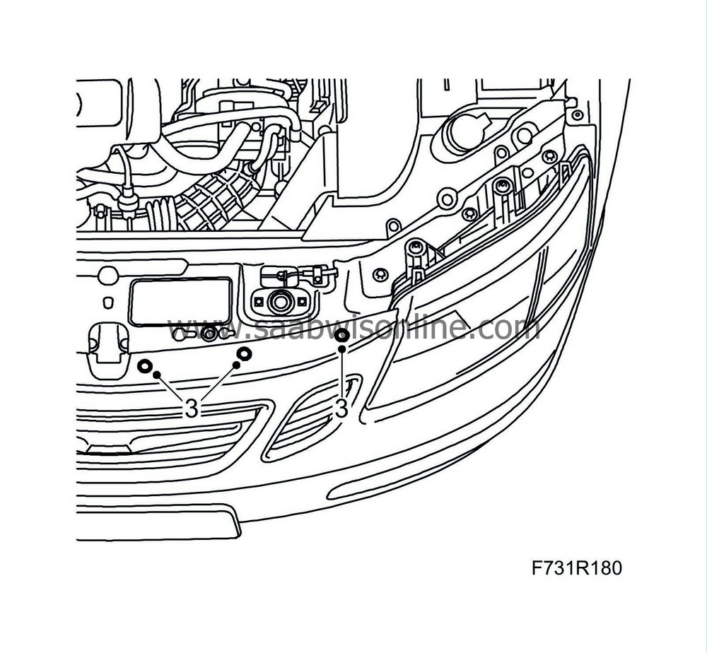
Remove the upper bumper shell attachments.
|
|
| 4. |
Remove the air filter cover.

|
||||||||||
| 5. |
Detach the hose between the air filter and mass air flow sensor. Remove the mass air flow sensor with hose.
|
|
| 6. |
Hang two
83 95 212 Straps
in place over the radiator member and the radiator unit so that they are accessible from below.
|
|
| 7. |
Raise the car.
|
|
| 8. |
Remove the front wheels.
|
|
| 9. |
Remove the lower front cover.
CV: Remove Chassis reinforcement, front subframe, CV . 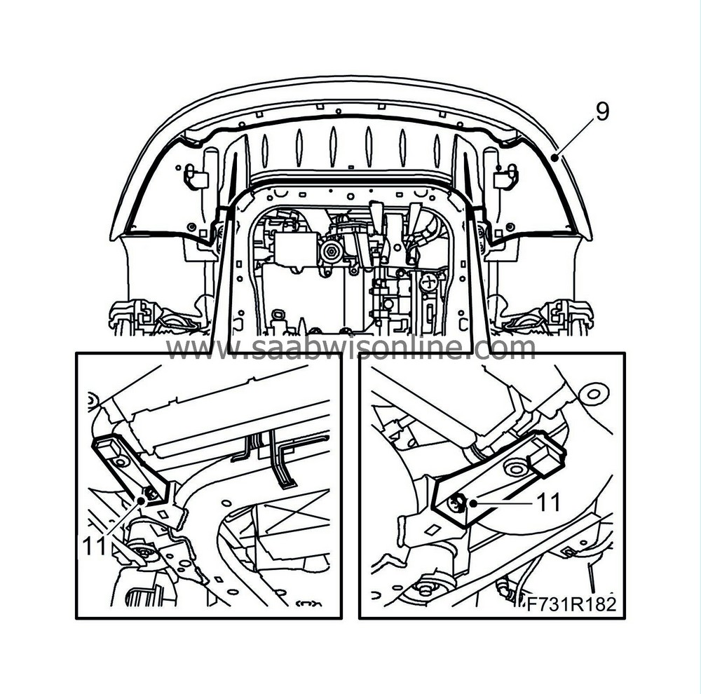
|
|
| 10. |
Bind the radiator unit tightly with the straps.
|
|
| 11. |
Remove the radiator brackets from the subframe.
|
|
| 12. |
Remove the front section of the exhaust system.

|
||||||||||
| 13. |
Remove the engine torque rod from the subframe.

|
|
| 14. |
Remove the bolt and nut which attach the suspension arm to the steering swivel member on both sides.
Left-hand suspension arm and cars with xenon lights: Remove the level sensor. 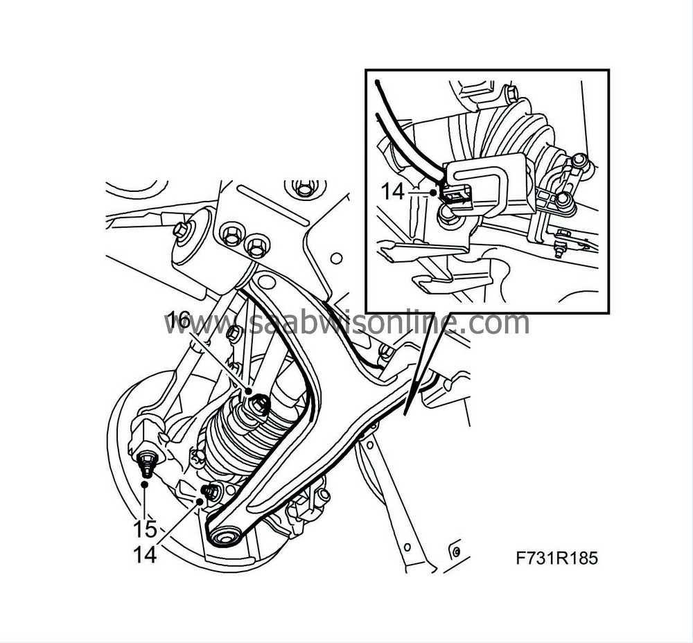
|
|
| 15. |
Remove the nut holding the track rod ends to the steering swindle member on both sides. Remove the track rod using
87 91 287 Puller, 150 mm
.
|
|
| 16. |
Remove the anti-roll bar links from the anti-roll bar. Counterhold with a thin 17 mm open wrench so that the ball joint does not rotate.
|
|
| 17. |
RHD:
Place a receptacle under the car. Detach the delivery line and return line from the steering gear. Plug the lines.

|
|
| 18. |
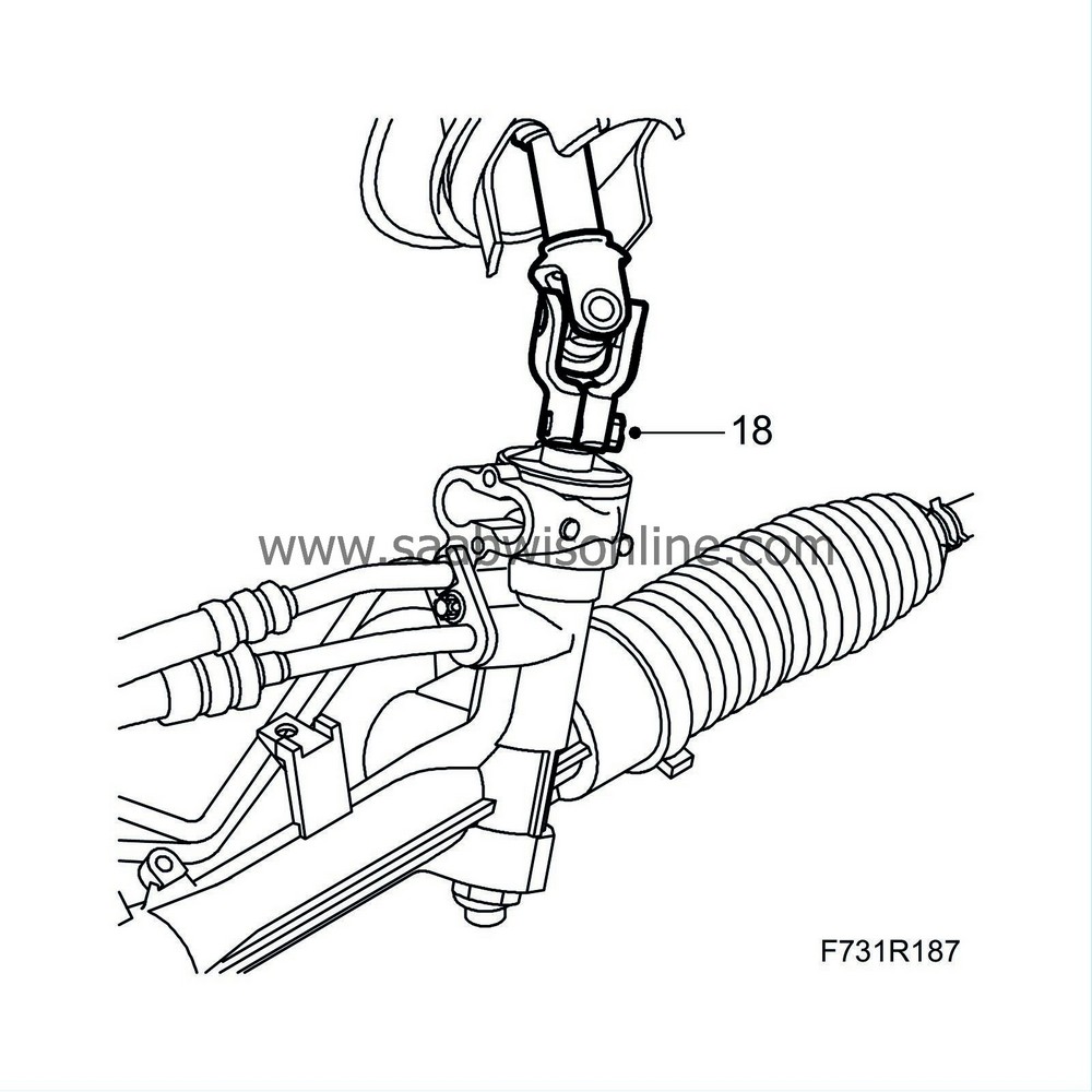
Remove the steering shaft joint from the steering gear.
|
|
| 19. |
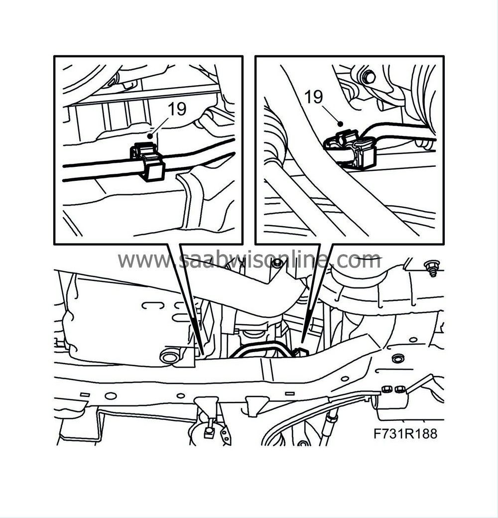
Open the clips that secure the power steering pipe to the subframe.
|
|
| 20. |
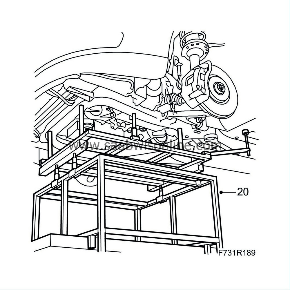
Position
83 95 311 Trolley lift
underneath. Fit
83 94 801 Parent fixture,
83 95 188 Basic fixture
,
83 95 170 Adapter
and
83 96 137 Centring tool, subframe - body
. Fit in the locating pins and use the adapters to adjust the height for even contact.
|
|
| 21. |
Remove the front part of the wing liner and fold away slightly.

|
|
| 22. |
Remove the subframe bolts on both sides. Remove the stays from the body.
|
|
| 23. |
Lower the subframe slightly.
|
|
| 24. |
Pull out the suspension arms ball-and-socket joints from the steering swivel members.
|
|
| 25. |
Place a receptacle beneath the car. Detach the delivery line and return line from the steering gear. Plug the lines.
LHD: 
RHD: Remove the delivery pipe from the clip on the steering gear. 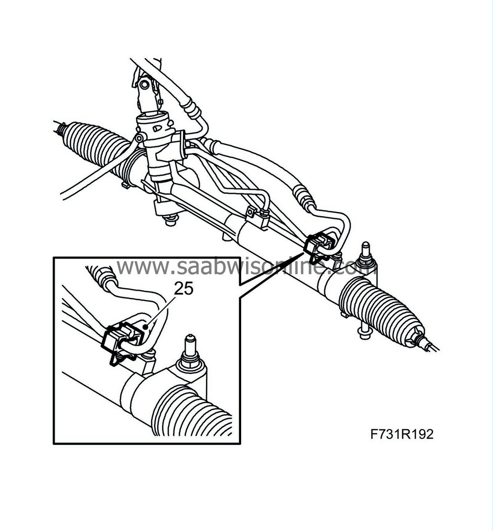
|
|
| 26. |
Lower the subframe.
|
|
| 27. |
Replace the anti-roll bar bushes.
|
|||||||||||||||||||
| 27.1. |
Remove the bolts of the left anti-roll bar bush.

|
| 27.2. |
Remove the cap from the bush.

|
| 27.3. |
Remove the upper bush.
|
|||||||
| 27.4. |
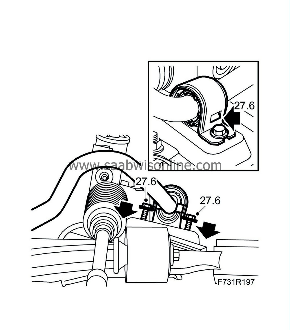
Fit the upper bush, centred in the cap.

|
| 27.5. |
Position the lower bush on the subframe, centred between the bolt holes.

|
| 27.6. |
Fit the cap with upper bush to the subframe. Tighten the bolts alternatingly until the lower bush's catches engage in the cap.
|
|||||||
| 27.7. |
Replace the temporary bolts (M8x30 mm) with the original bolts and tighten.
Tightening torque 18 Nm (13 lbf ft). |
| 27.8. |
Replace the right anti-roll bar bush following the same method.
|
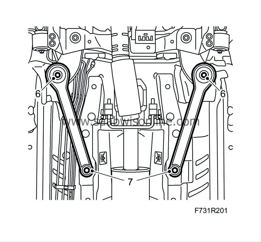
| To fit |
| 1. |
Lift the frame.
Fit the ball joints for the suspension arms in the steering swivel member. |
|
| 2. |
LHD:
Fit the delivery line and return line to the steering gear using new O-rings.
Tightening torque 12 Nm (9 lbf ft). 
|
|
| 3. |
Lift the subframe into place and align
83 96 137 Centring tool, subframe - body
with the locating holes in the body.
|
|
| 4. |
Attach the power steering pipe to the plastic clips on the subframe.
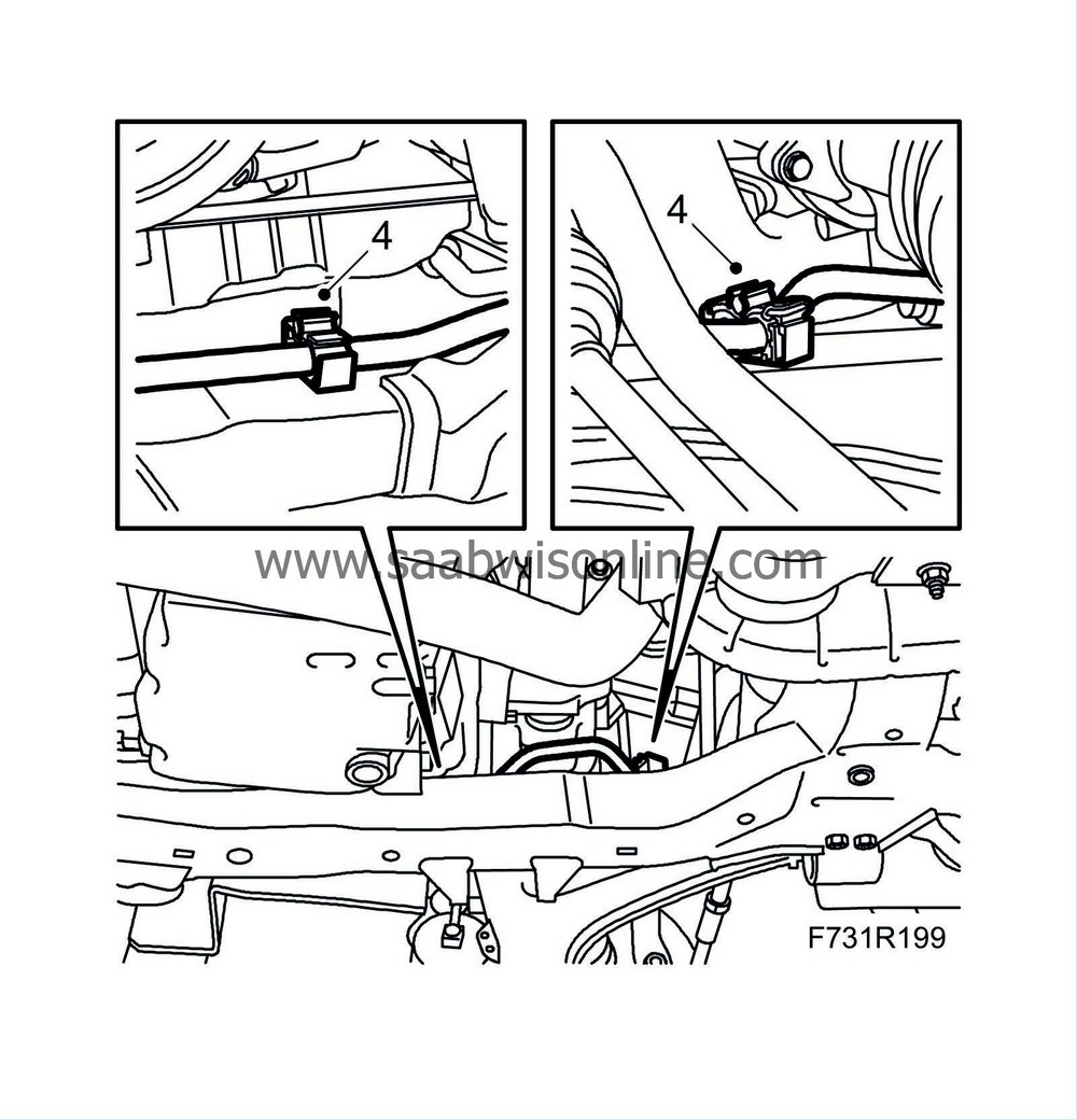
|
|
| 5. |
Lift the subframe so that the inner sections of the bushes are pressing against the body. Fit the front subframe bolts on both sides.
Tightening torque 75 Nm +135° (55 lbf ft +135°) 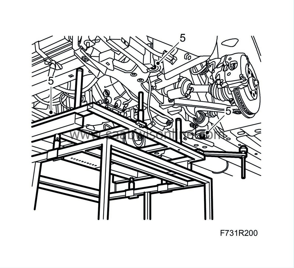
|
|
| 7. |
Tighten the rear stay bolts.
Tightening torque 90 Nm +45° (66 lbf ft +45°) |
|
| 8. |
RHD:
Attach the delivery line and return line to the steering gear using new O-rings. Fit the delivery pipe in the clips on the steering gear.
Tightening torque 12 Nm (9 lbf ft). 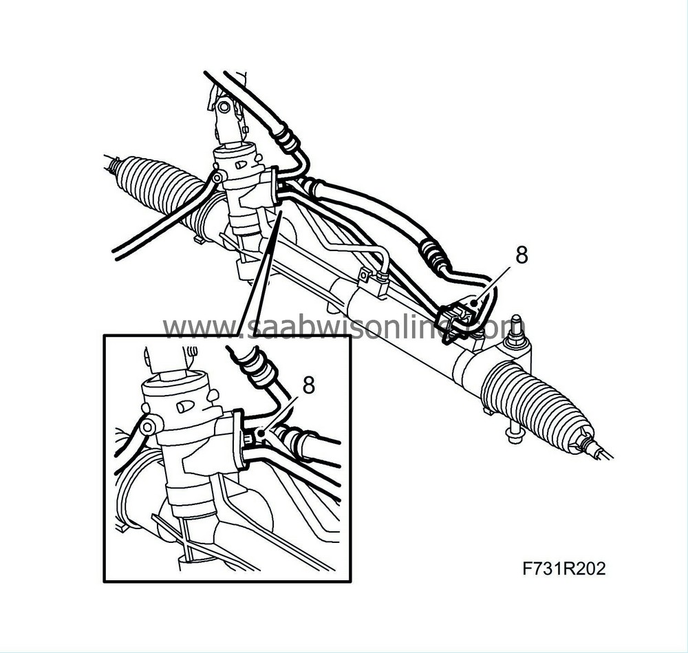
|
|
| 9. |
Fit the engine torque rod to the subframe.
Tightening torque, rear torque rod 80 Nm (59 lbf ft) Tightening torque, front torque rod 60 Nm +90° (44 lbf ft +90°) 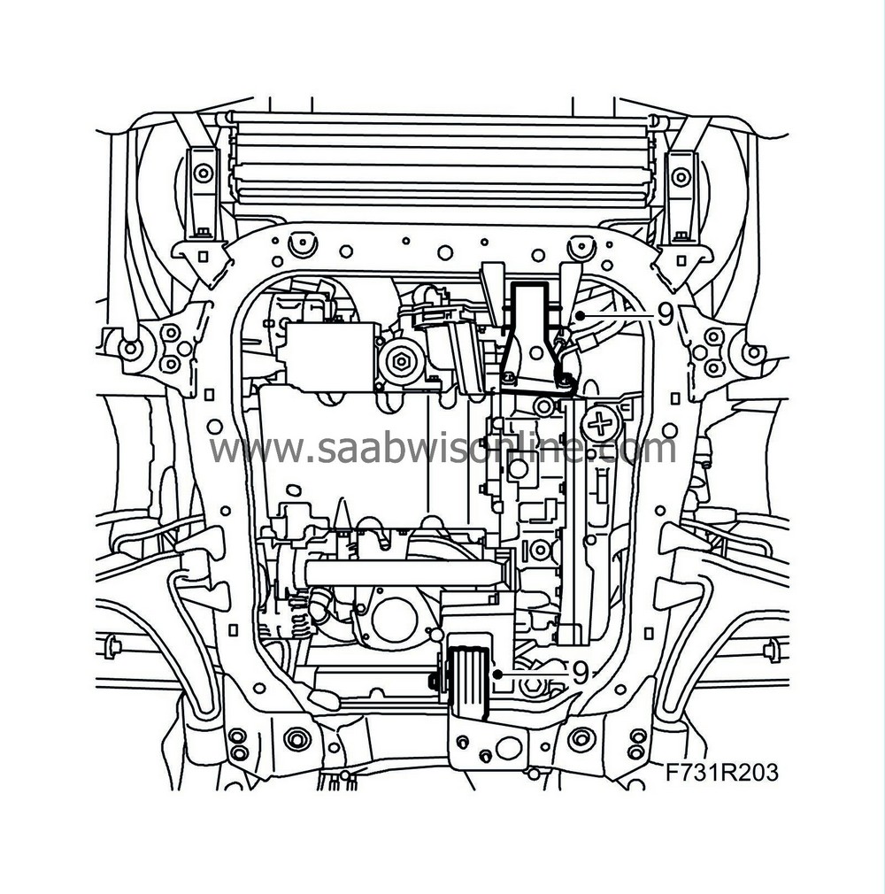
|
|
| 10. |
Set up
83 96 145 Centring tool, subframe - engine
and check that the engine and gearbox are correctly positioned in relation to the subframe.
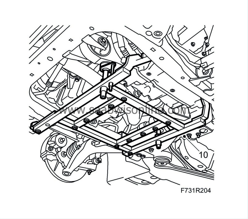
Remove the centring tool. |
|
| 12. |
Install the anti-roll bar links to the anti-roll bar. Counterhold with a thin 17 mm open wrench so that the ball joint does not rotate.
Tightening torque 64 Nm (47 lbf ft) |
|
| 13. |
Fit the track rod ends to the steering swivel members.
Tightening torque 35 Nm (26 lbf ft) |
|
| 14. |
Attach the steering shaft joint to the steering gear. Clean the threads and apply
Thread locking adhesive, Loctite 242
to the threads.
Tightening torque 30 Nm (22 lbf ft) 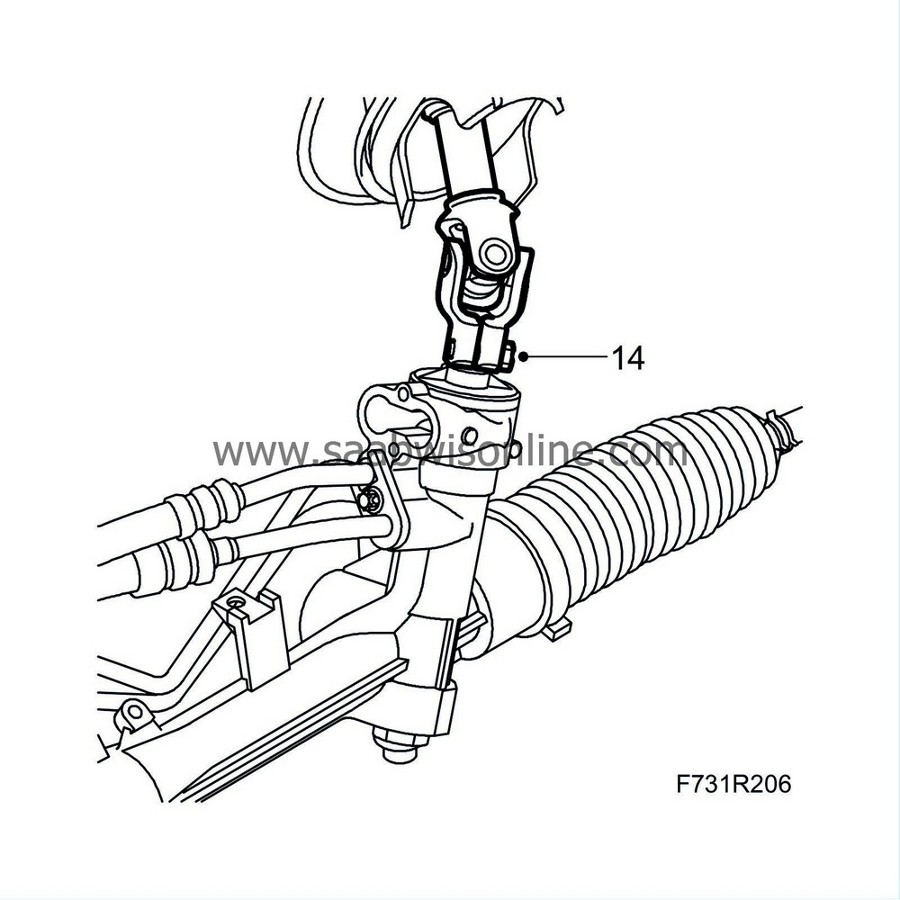
|
|||||||||
| 15. |
Fit the radiator brackets to the subframe.
Tightening torque 47 Nm (35 lbf ft)

|
|||||||
| 16. |
Remove the straps.
|
|
| 17. |
Fit the front exhaust pipe section.
Tightening torque 30 Nm (22 lbf ft) Clamp: Tightening torque 40 Nm (30 lbf ft)

|
||||||||||
| 18. |
Fit the front part of the wing liner on both sides of the car.
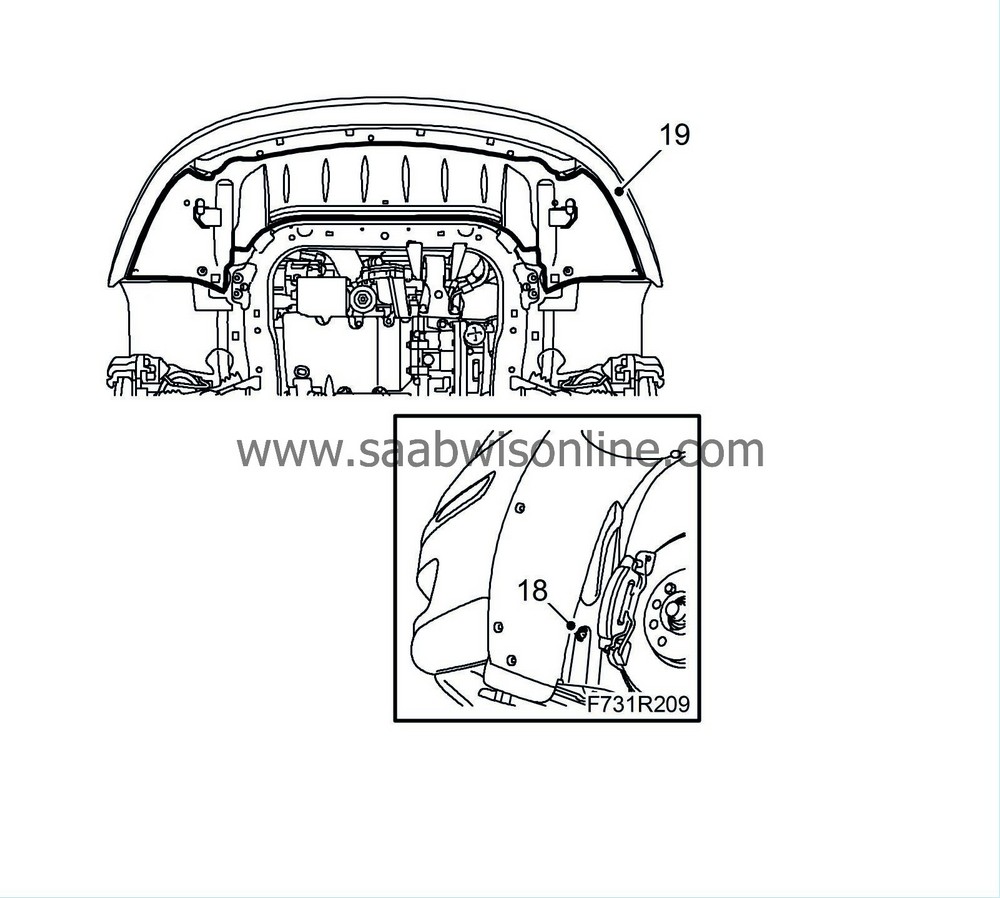
|
|
| 19. |
CV:
Fit Chassis reinforcement, front subframe, CV
.
Fit the lower front cover. |
|
| 20. |
Fit the
wheels
.
|
|
| 21. |
Lower the car to the floor.
|
|
| 22. |
Fit the upper bumper shell attachments.
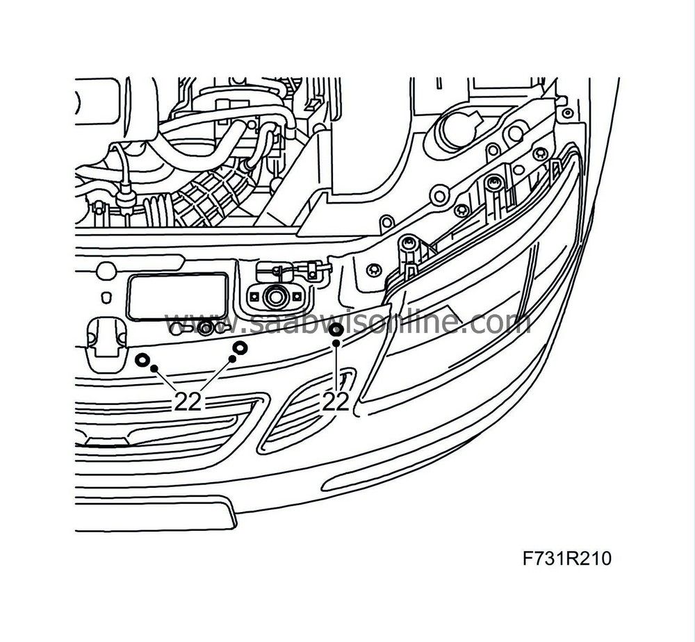
|
|
| 23. |
Attach the hose with mass air flow sensor to the turbocharger and attach the hose between the mass air flow sensor and the air filter.

|
|
| 24. |
Fit the air filter cover.
|
|
| 25. |
Remove the hose pinch-off pliers and fill with
Power steering fluid
.
|
|
| 26. |
Remove the steering wheel fixing.
|
|
| 27. |
Bleed the power steering system
and check for leaks.
|
|
| 28. |
Check the straight-ahead position of the steering wheel when driving on a level road. Adjust if necessary.
|
|

 Warning


