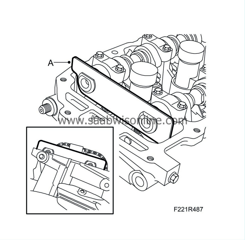
Valve mechanism, rear cylinder head, B284 (new version)
| Valve mechanism, rear cylinder head, B284 (new version) |
| To remove |
| Important | ||
|
Store all removed valve parts in the valve stand 83 93 787. |
||
| 1. |
Remove the
Camshaft cover, rear, B284
|
|
| 2. |
Remove the spark plugs.
|
|
| 3. |
Remove the camshaft solenoid valve (695R) (A).

|
|
| 4. |
Remove the camshaft position sensor (555R) (B).
|
|
| 6. |
Raise the car.
|
|
| 7. |
Remove the
Starter motor, B284
.
|
|
| 8. |
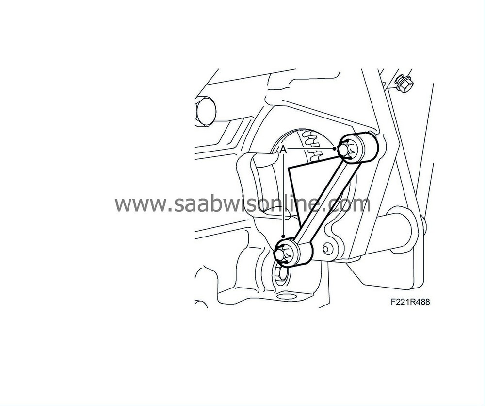
Fit
EN-46106 Flywheel locking attachment
(A).
|
|
| 9. |
Lower the car.
|
|
| 10. |
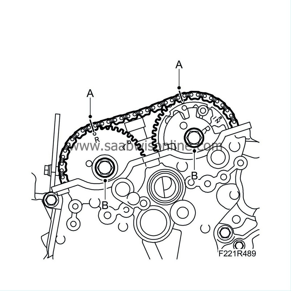
Mark the chain and camshaft sprockets so they can be refitted in the same position (A).
|
|
| 11. |
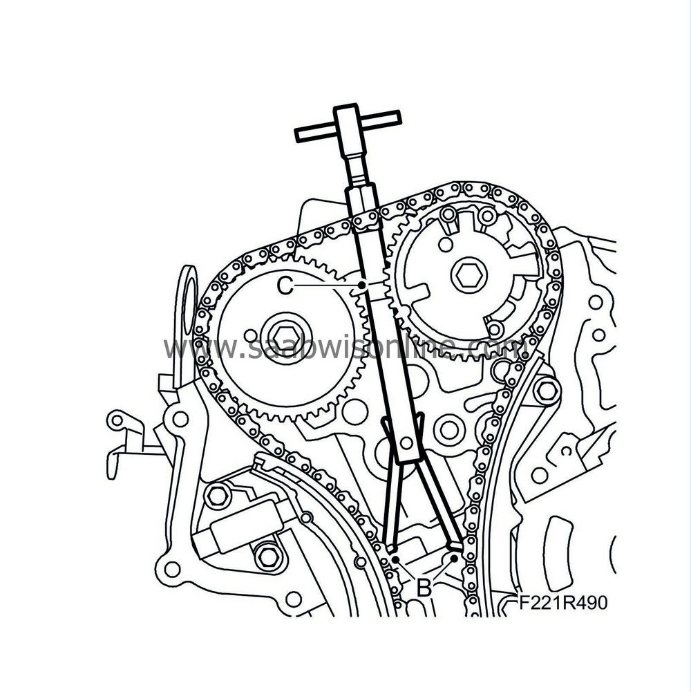
Slightly loosen the bolts holding the camshaft sprockets. Counterhold using an open spanner on the camshaft flats (do not remove the bolts) (B).
|
|
| 13. |
Tighten EN-48313 Fixing tool manually so that the chain is unloaded. Counterhold using an open spanner so that the tool does not turn.
|
||||||||||
| 14. |
Remove the camshaft sprocket bolts.
|
|
| 15. |
Remove the sprockets from the camshafts.
|
|
| 17. |
Lift out the camshafts and note the rear marking on the camshafts. (B) The last letters in the marking: RI = intake camshaft, rear cylinder bank. RE = exhaust camshaft, rear cylinder bank.
|
|
| 18. |
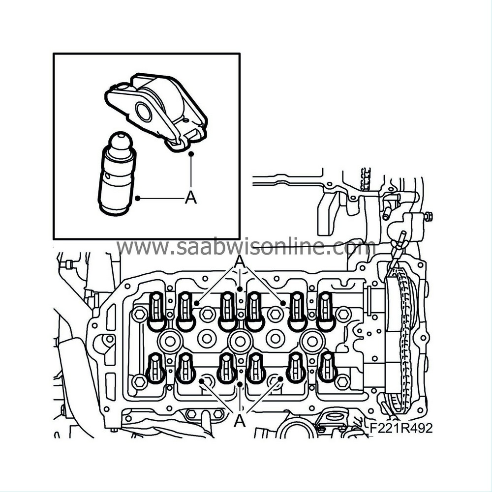
Remove the roller rockers and the hydraulic adjuster elements. Store them in
83 93 787 Valve stand
so they do not get mixed up (A).
|
||||||||||
| 19. |
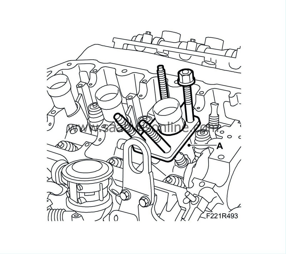
Fit
EN-46110 Valve spring tool
.
|
|
| 20. |
Fit
83 94 173 Air nipple for spark plug hole
. Connect compressed air and put the piston and valves under pressure (A).

|
|
| 21. |
Press down the valve plate with
EN-46110 Valve spring tool
(B).
|
||||||||||
| 22. |
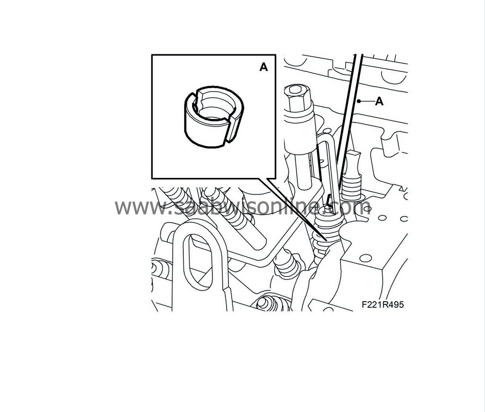
Remove the valve cone with a magnet (A).
|
|
| 23. |
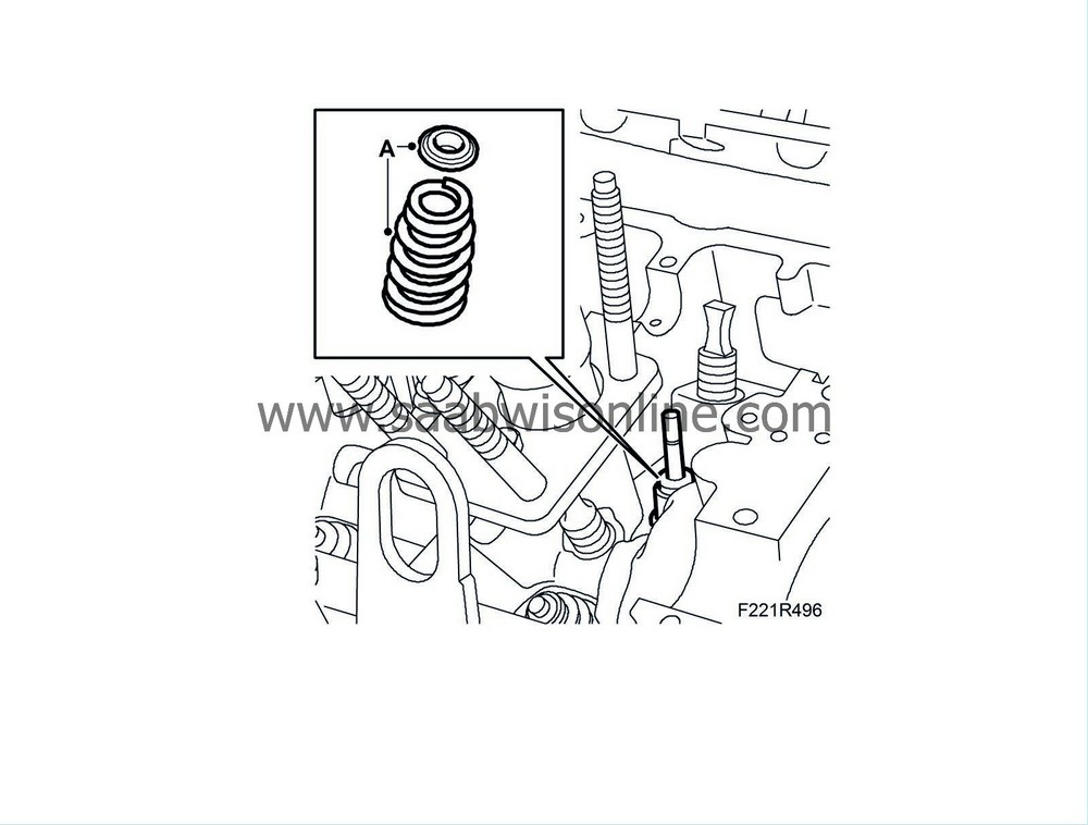
Lift out the spring plate and valve spring (A).
|
|
| 24. |
Lift out the valve guide seal using
83 94 157 Pliers, valve guide seal
(A).
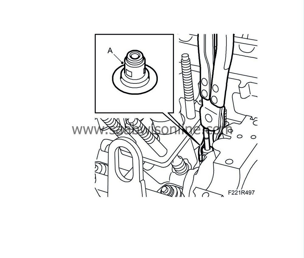
|
|
| To fit |
| 1. |
Clean all parts and check contact surfaces and bearing surfaces for wear.
|
|
| 2. |
Fit the valve guide seal using
83 94 157 Pliers, valve guide seal
(A).

|
|
| 3. |
Fit the valve spring and spring plate (A).

|
|
| 4. |
Press down the valve plate with
EN-46110-eu Valve spring tool
.
|
|
| 5. |
Fit the valve cone using
EN-46117 Fitting tool
(A).
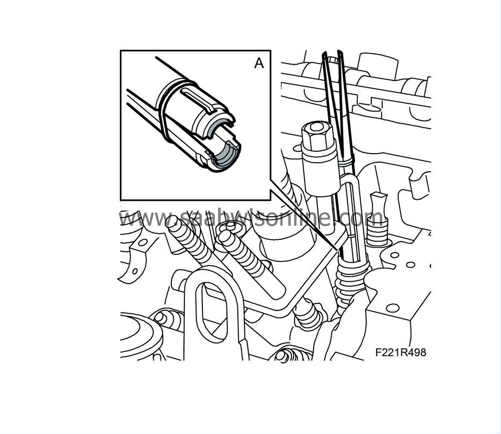
|
|
| 6. |
Unload the valve and remove
EN-46110-eu Valve spring tool
.
|
|
| 7. |
Disconnect the compressed air and remove the air nipple.
|
|
| 9. |
Fit the bearing caps as illustrated (markings on caps). Start where the cams point down and load the tappets.
Tightening torque 10 Nm (7 lbf ft)
|
||||||||||
| 10. |
Fit the sprockets with chain on the camshafts. Tighten the bolts by hand.
|
|
| 11. |
Check that the markings on the chain match the markings on the sprockets (A).

|
|
| 12. |
Remove EN-48313 Fixing tool.
|
|
| 13. |
Tighten the bolts of both camshaft sprockets (B), counterholding with an open spanner on the camshaft flats.
Tightening torque: 65 Nm (48 lbf ft) |
|
| 14. |
Fit the camshaft position sensor (555R) using a new gasket. (B)
Tightening torque 10 Nm (7 lbf ft) 
|
|
| 15. |
Fit the camshaft solenoid valve (695R) using a new seal (A).
Tightening torque 10 Nm (7 lbf ft) |
|
| 16. |
Fit the spark plugs.
|
|
| 17. |
Raise the car.
|
|
| 18. |
Remove
EN-46106 Flywheel locking attachment
(A).

|
|
| 19. |
Fit the
Starter motor, B284
.
|
|
| 20. |
Lower the car.
|
|
| 21. |
Fit the
Camshaft cover, rear, B284
|
|

