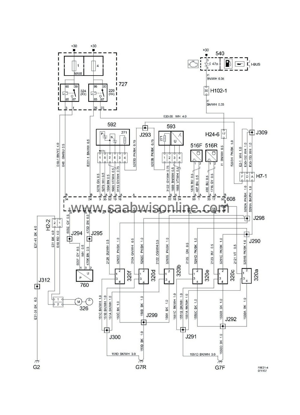
|
No.
|
Name
Location
|
Illus.
|
|
|
Components
|
|
|
229
|
Main relay, engine control system
in the main fuse box in front of battery
|

|
|
271
|
Heated oxygen sensor element,
integrated in the oxygen sensor
|

|
|
320a
|
Ignition coil with integrated power stage, cyl. 1,
on the spark plug
|

|
|
320b
|
Ignition coil with integrated power stage, cyl. 2,
on the spark plug
|

|
|
320C
|
Ignition coil with integrated power stage, cyl. 3,
on the spark plug
|

|
|
320D
|
Ignition coil with integrated power stage, cyl. 4,
on the spark plug
|

|
|
320e
|
Ignition coil with integrated power stage, cyl 5
on the spark plug
|

|
|
320f
|
Ignition coil with integrated power stage, cyl 6
on the spark plug
|

|
|
324
|
Secondary air injection pump relay
in UEC 727
|

|
|
326
|
Motor, injection pump, secondary air,
at bottom of engine front
|

|
|
516F
|
Knock sensor, front cylinder bank
at rear edge of starter motor
|

|
|
516R
|
Knock sensor, rear cylinder bank
in the centre of the rear cylinder bank
|

|
|
540
|
Main instrument unit,
in front of driver in instrument panel
|

|
|
592
|
Front heated oxygen sensor,
component:
before/on the catalytic converter
connector:
at rear corner of upper intake manifold on gearbox side below connector H7-1
|

|
|
593
|
Rear heated oxygen sensor,
component:
after the catalytic converter
connector:
below the engine control module
|

|
|
608
|
Control module, V6 petrol
at the top of the rear cylinder bank
|
A
B
|
|
727
|
Main fuse box 727 in engine bay
,
in front of battery
|
1
4
|
|
760
|
on the delivery pipe from the secondary air pump
|

|
|
|
2 pin connector
|
|
|
H2-2
|
In engine bay at right headlamp
|

|
|
|
7-pin connector
|
|
|
H7-1
|
On engine at rear corner of upper intake manifold on gearbox side
|

|
|
|
24-pin connector
|
|
|
H24-6
|
Grey connector in front of the battery of the side of the left structure strut
|

|
|
|
102-pin connector
|
|
|
H102-1
|
Under left A-pillar
|

|
|
|
Crimp connections
|
|
|
J290
|
Approx. 50 mm from branching of cylinder 1 ignition coil toward grounding point G7R
|

|
|
J291
|
Approx. 30 mm from branching of cylinder 3 ignition coil toward grounding point G7R
|

|
|
J292
|
Approx. 30 mm from branching of cylinder 5 ignition coil toward grounding point G7R
|

|
|
J293
|
Approx. 110 mm from branching of engine control module toward front cylinder bank
|

|
|
J294
|
Approx. 70 mm from branching of engine control module toward engine control module
|

|
|
J295
|
Approx. 70 mm from branching of engine control module toward engine control module
|
LONK
|
|
J298
|
Approx. 110 from branching of cylinder 2 ignition coil toward rear cylinder bank
|

|
|
J299
|
Approx. 40 mm from branching of cylinder 2 ignition coil toward cylinder 4
|

|
|
J300
|
Approx. 60 mm from grounding point G7F
|

|
|
J309
|
Approx. 270 mm from branching of battery toward engine control module
|

|
|
J312
|
Approx. 180 mm from branching of battery toward engine control module
|

|
|
|
Grounding points
|
|
|
G2
|
On the side of the left structure strut by the connector bracket
|

|
|
G7F
|
In the centre of the front cylinder bank
|

|
|
G7R
|
On the rear cylinder bank toward the gearbox side
|

|


