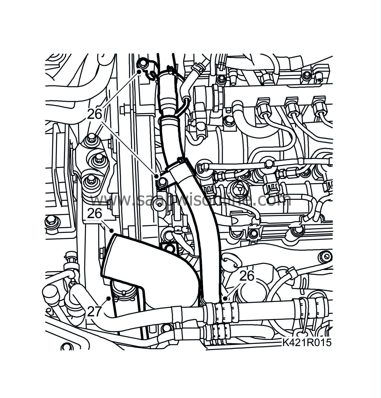
Power unit, removal, Z19DT/DTH
| Power unit, removal, Z19DT/DTH |
|
|||||||||||||
| To remove |
| 1. |
Place the car on a lift and apply wing covers.
|
|
| 2. |
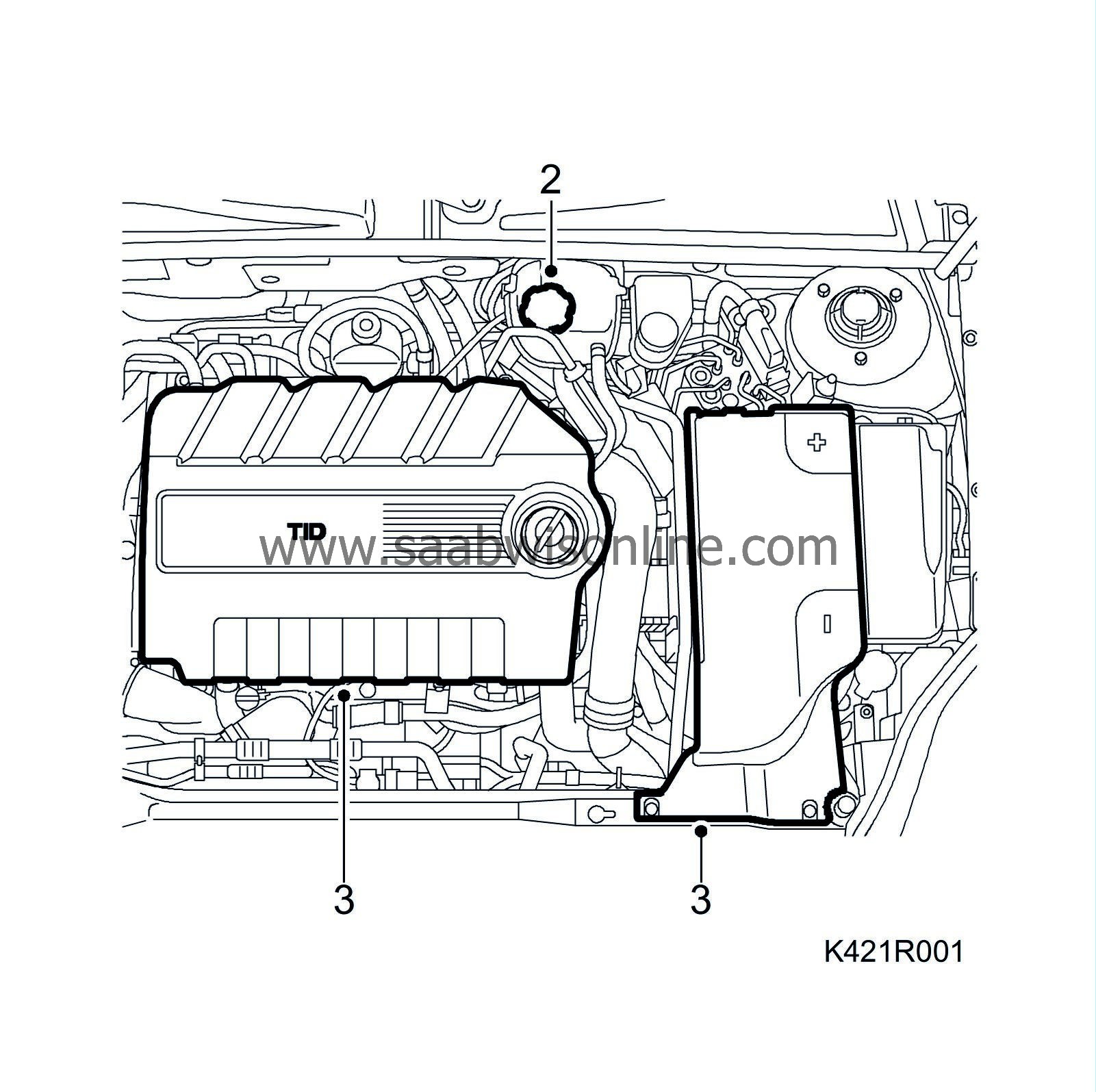
Open the cap on the expansion tank.
|
|
| 3. |
Remove the upper engine cover, insulation and battery cover.
|
|
| 4. |
Remove the battery cable.
|
|
| 5. |
Remove the battery.
|
|
| 6. |
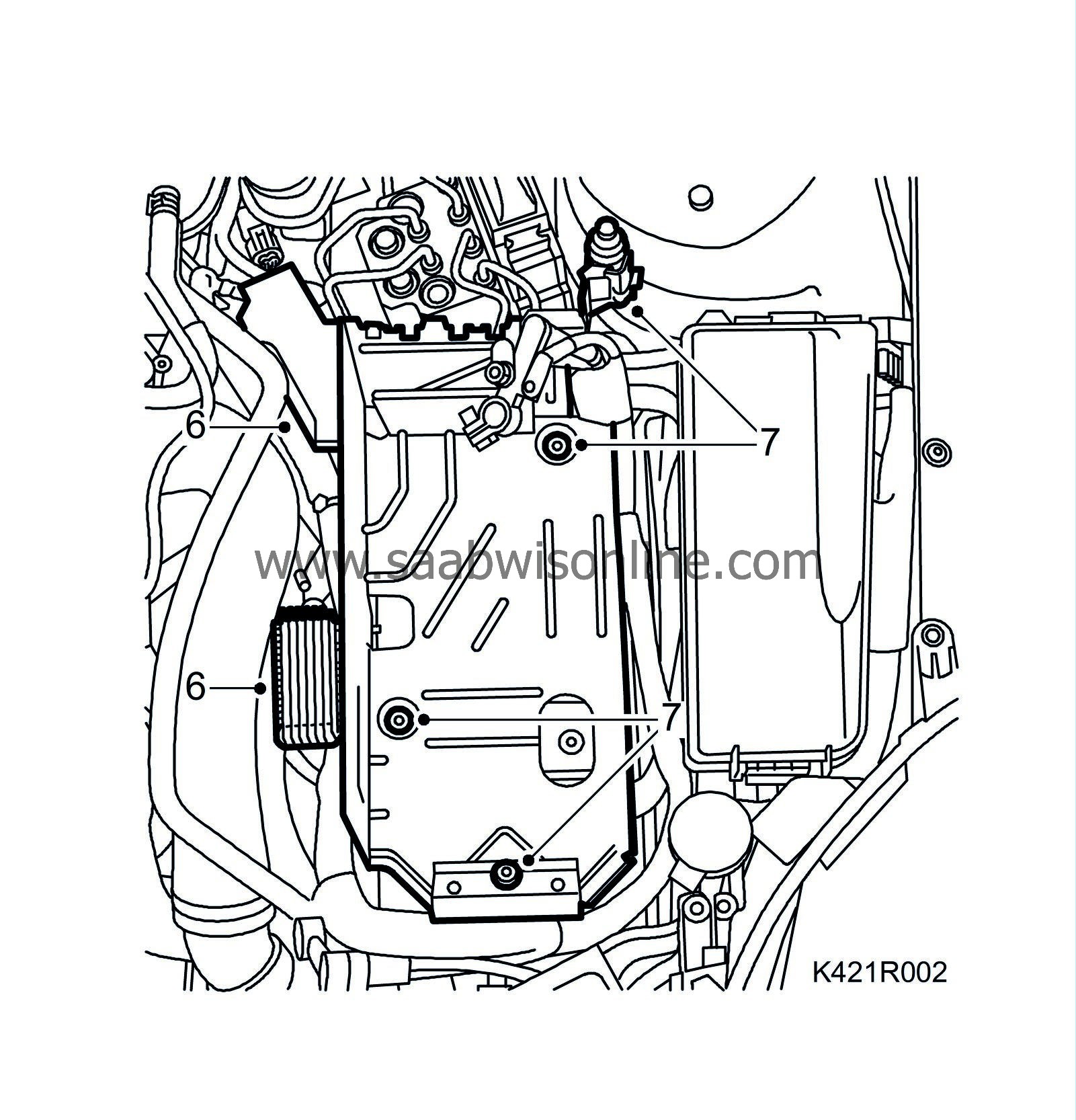
Remove the glow plug control module and fuse holder from the battery tray.
|
|
| 7. |
Unplug the bonnet switch connector and remove the battery tray.
|
|
| 8. |
Raise the car slightly and remove the front wheels.
|
|
| 9. |
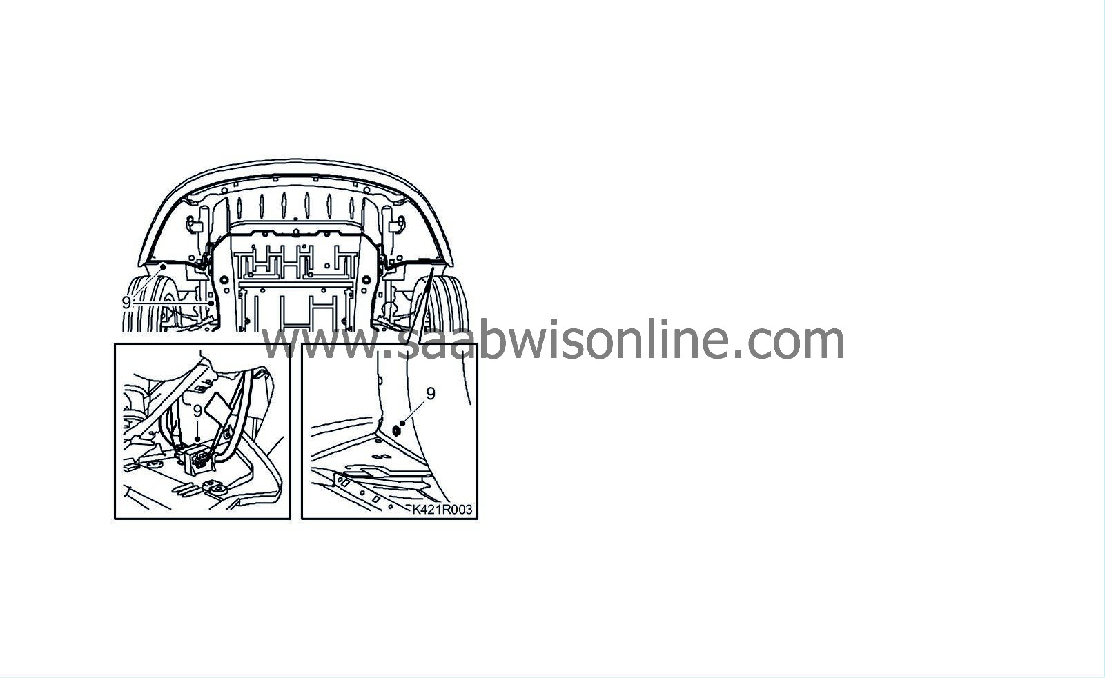
Raise the car and remove the lower engine cover as well as the front spoiler shield. Unplug and remove the connector.
|
|
| 10. |
Remove the right wing liner and detach the front part of the left wing liner so that the subframe is free.

|
|
| 11. |
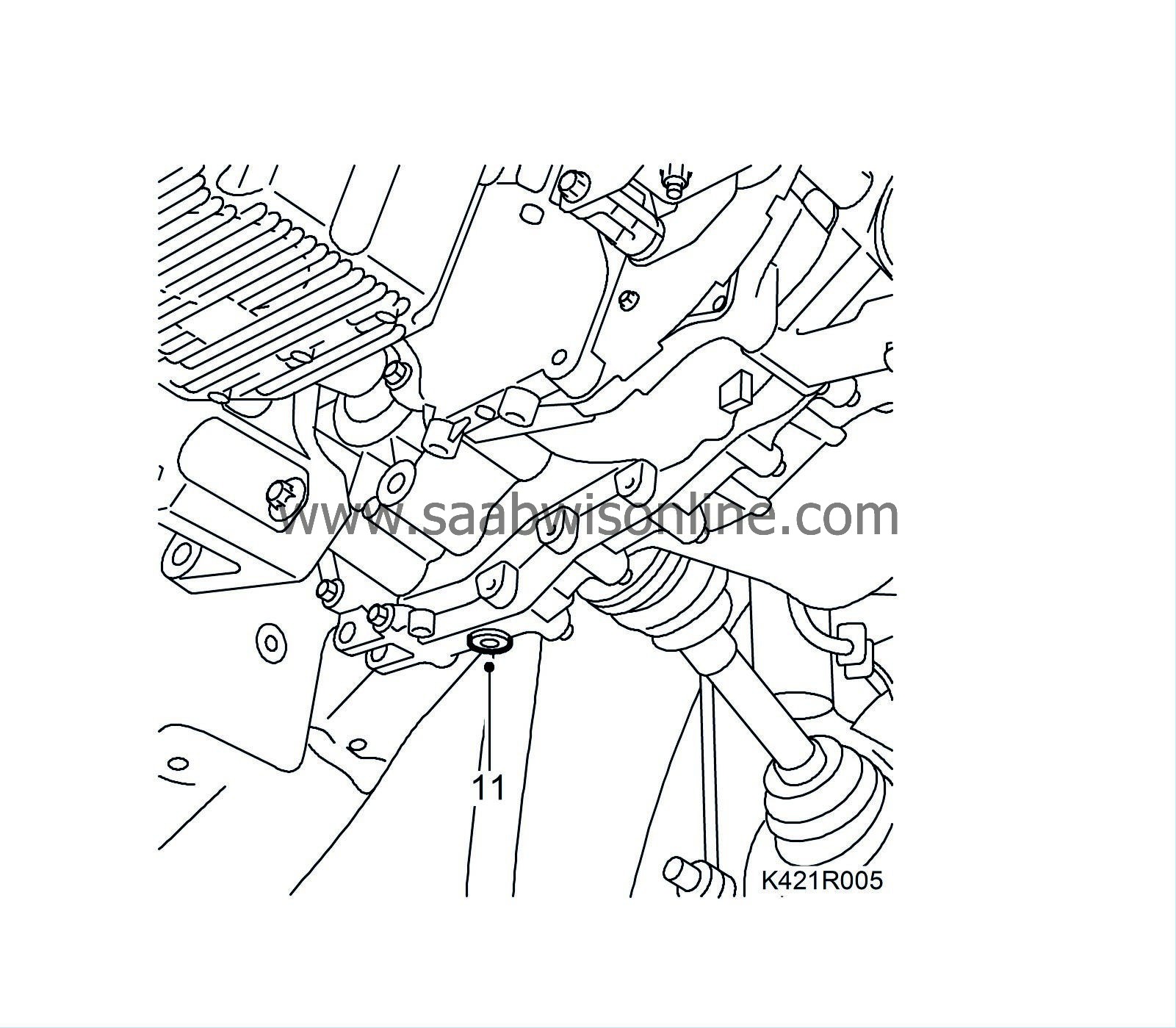
Undo the gearbox drain plug and drain off the gearbox oil.
|
|
| 12. |
Fit the drain plug.
Tightening torque 50 Nm (37 lbf ft) |
|
| 13. |
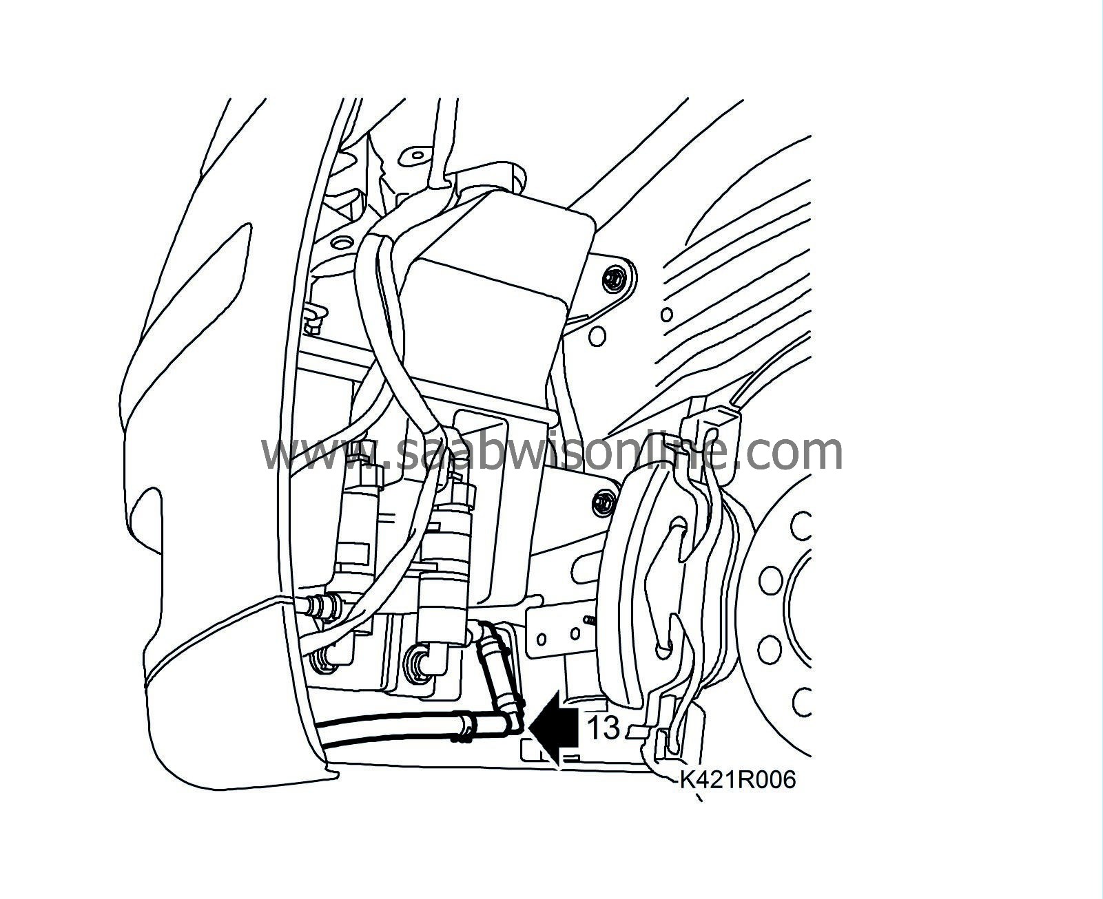
Detach the headlight washer hose and plug the washer fluid reservoir.
|
|
| 14. |
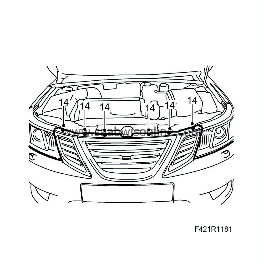
Lower the car slightly and remove the bumper.
|
|
| 15. |
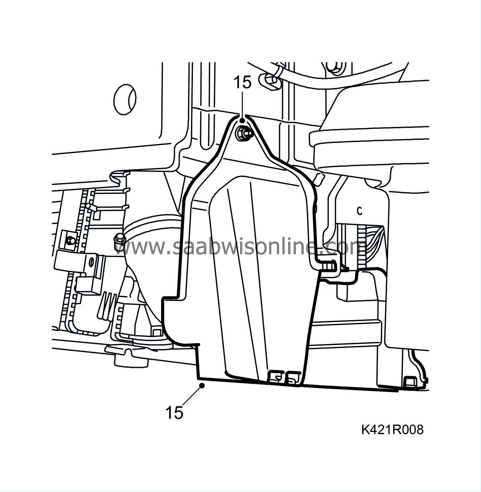
Remove the cover on the left-hand side.
|
|
| 16. |
Remove the cover on the right-hand side and remove the connectors and clips from the engine control module.

|
|
| 17. |
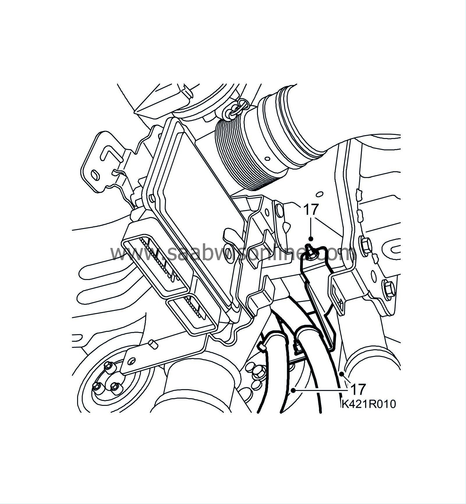
Remove the bracket from the body and the engine wiring harness.
|
|
| 18. |
Lower the car.
|
|
| 19. |
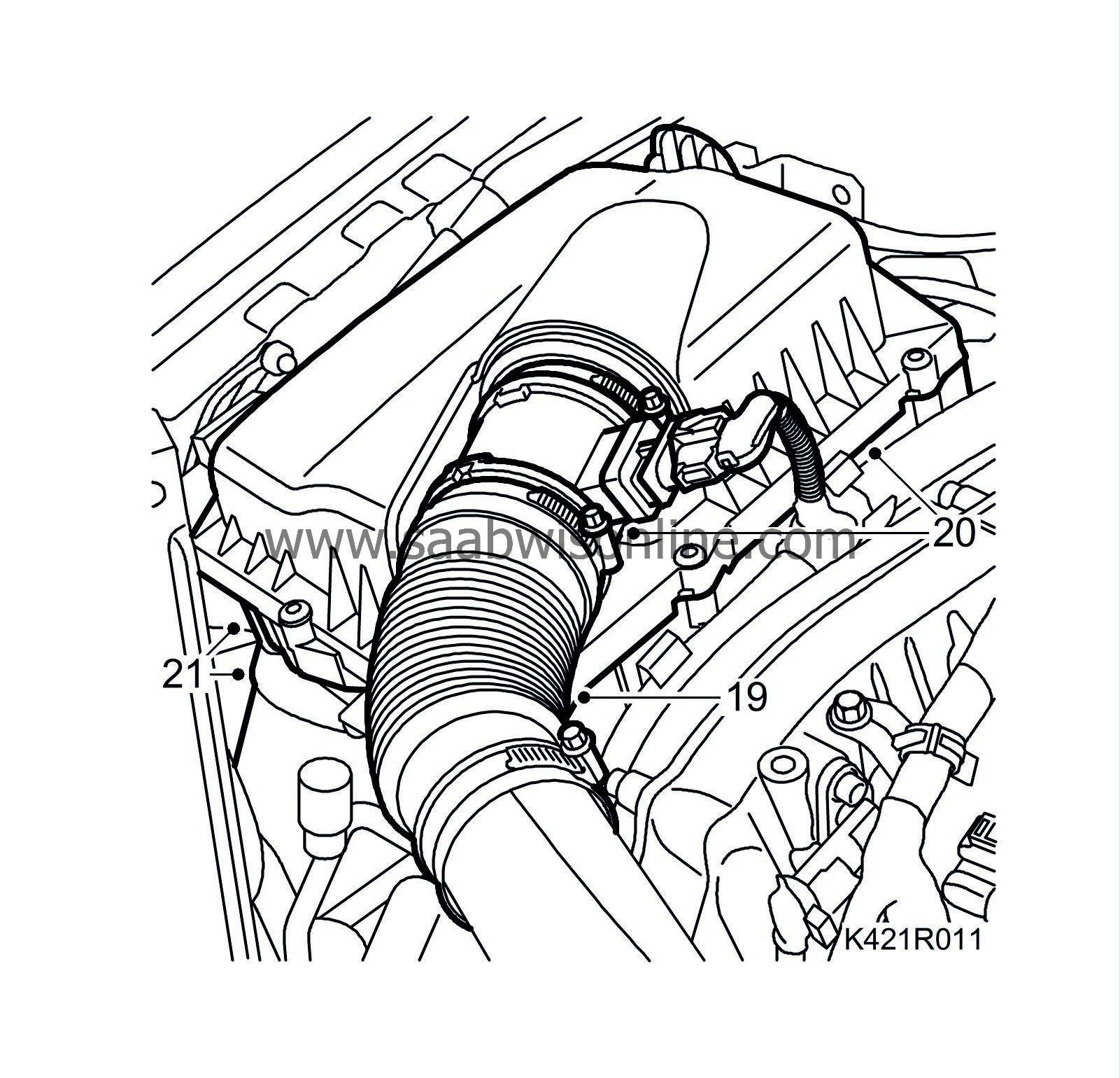
Remove the turbocharger intake hose.
|
|
| 20. |
Remove the mass air flow sensor connector, air cleaner casing cover and air filter.
|
|
| 21. |
Detach the intake hose and remove the air cleaner casing.
|
|||||||||||||||||||||||||||||||||
| 22. |
Detach the fuel return hose. Plug both the hose and the pipe.

|
|
| 23. |
Detach the fuel inlet hose. Plug both the hose and the pipe.
|
|
| 24. |
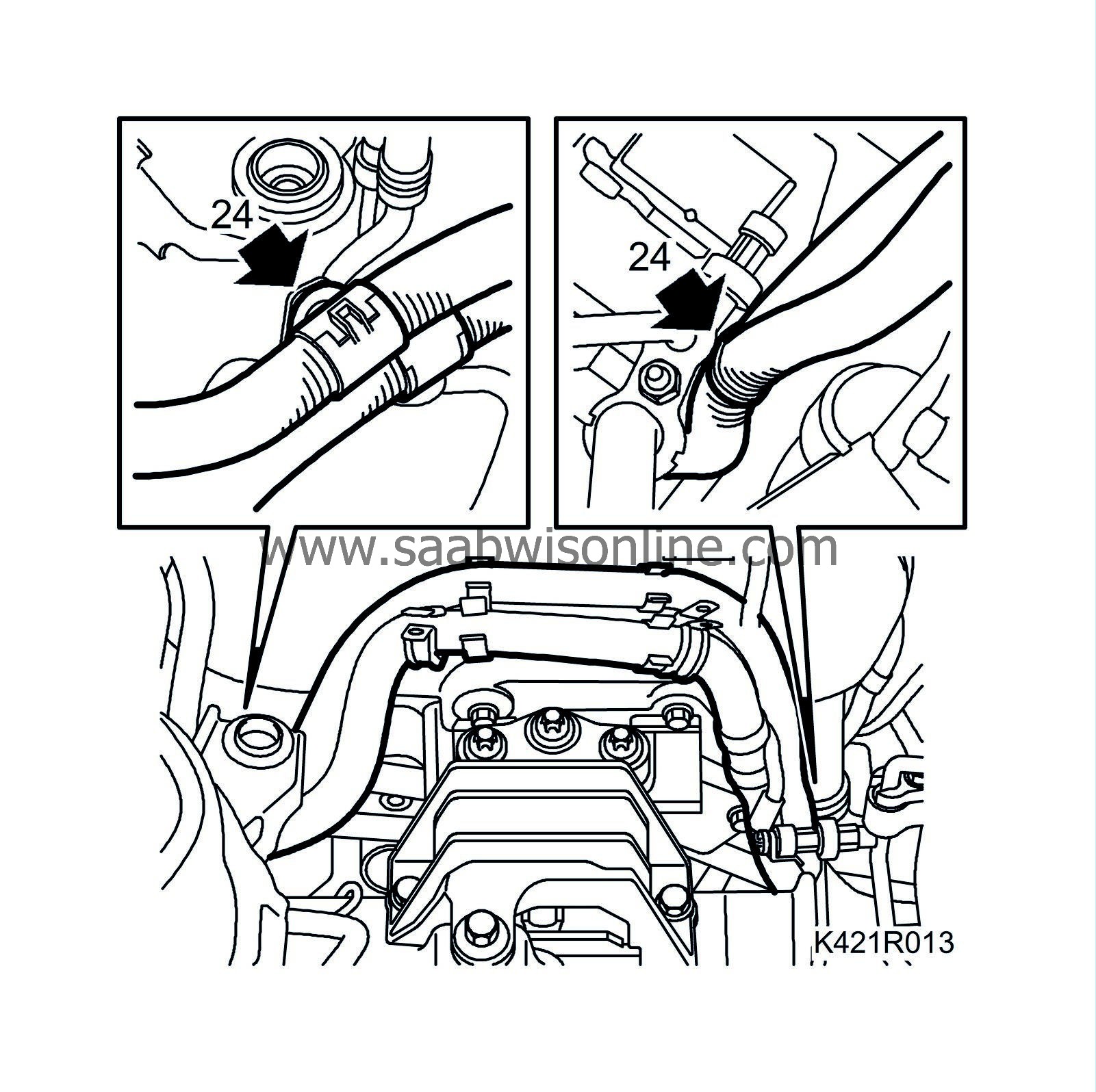
Remove the fixings from the right structural member (front and rear). Carefully lift up the engine control module's wiring harness.
|
|
| 25. |
Remove the turbo delivery pipe and hose from the turbocharger outlet.

|
|
| 27. |
Detach the lower radiator hose from the engine.
|
|
| 28. |
Disconnect the hose with quick coupling from the vacuum pump.

|
|
| 29. |
Remove the turbocharger delivery hose from the throttle body and the turbo delivery pipe
|
|
| 30. |
Remove the upper radiator hose.
|
|
| 31. |
Detach the bleeder hose from the radiator.
Aut:
Detach the oil pipes from the radiator using
87 92 806 Removal tool, oil pipe, automatic transmission
.

|
|
| 32. |
Remove the windscreen washer filler pipe.
|
|
| 33. |
Remove the cover on the main fuse box and undo the two retaining screws.
|
|
| 34. |
Disconnect the positive cable from the battery.
|
|
| 35. |
Undo the screw securing the engine wiring harness connector in the electrical centre.
|
|
| 36. |
Remove the engine harness clamp from the body and the ground cables.
|
|
| 37. |
Detach the connector from the left structural member.
|
|
| 38. |
Remove the radiator fan connector.

|
|
| 39. |
Unplug the connector from the turbocharger solenoid valve.
|
|
| 40. |
Detach the vacuum hoses from the turbocharger solenoid valve.
|
|||||||
| 41. |
Detach the wiring harness from the fan cowling.
|
|
| 42. |
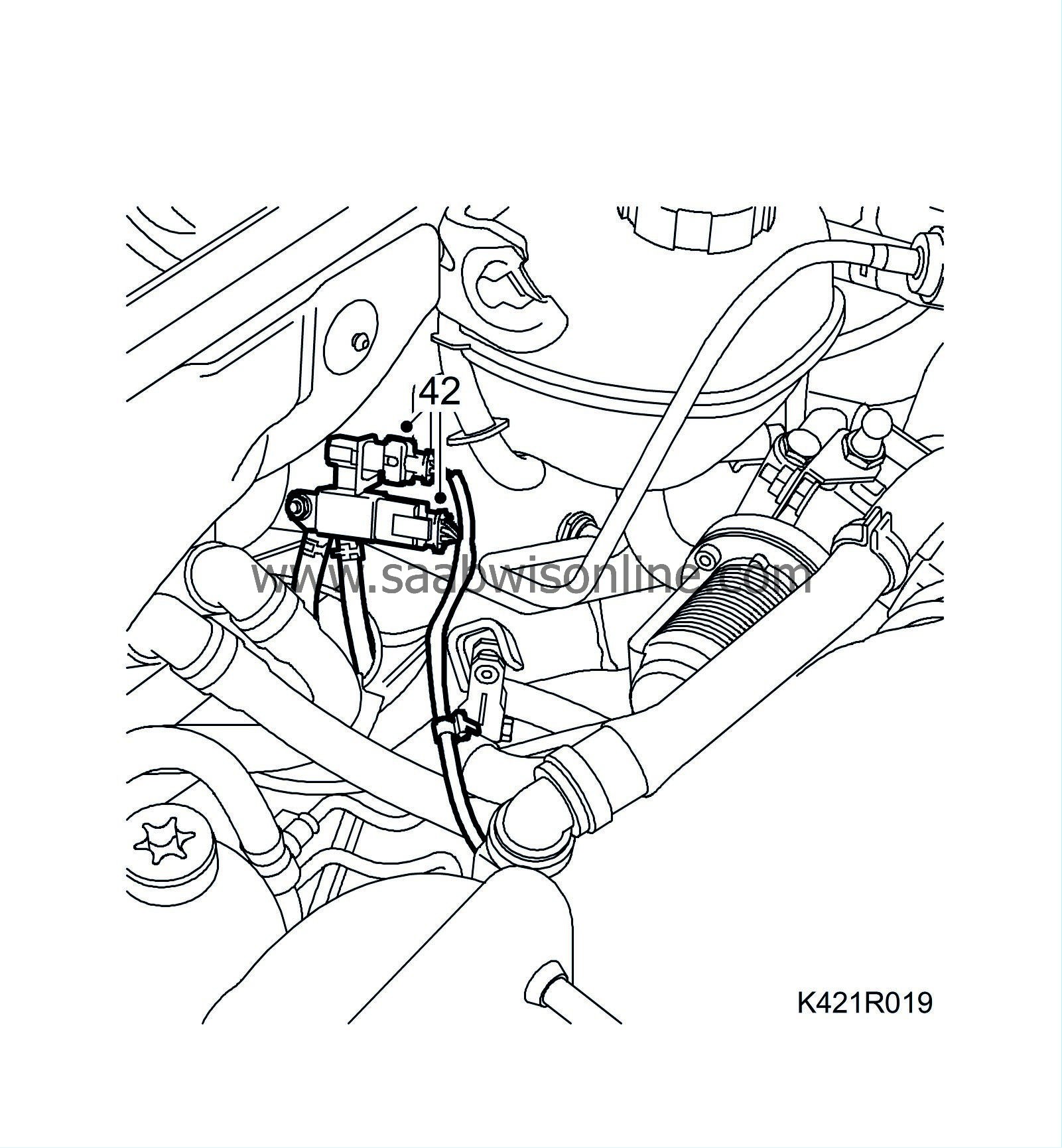
Unplug the connector from the particle filter pressure sensor and the rear temperature sensor.
|
|
| 43. |
Fold up the engine wiring harness onto the engine.
|
|
| 44. |
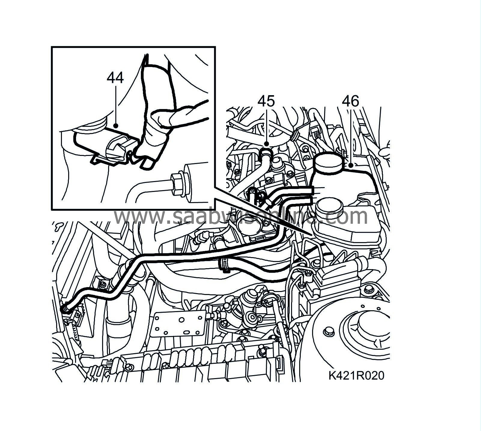
Unplug the coolant level sensor connector.
|
|
| 45. |
Detach the vent hose from the engine.
|
|
| 46. |
Detach the expansion tank from the body and remove the tank together with the hose.
|
|
| 47. |
Remove the gear cables from the gearbox. Carefully bend the cables aside and secure them to the expansion tank bracket on the body using a cable tie.

|
|
| 48. |
Fit
30 07 739 Hose pinch-off pliers
to the clutch hose and disconnect the quick-release coupling from the clutch slave cylinder.
|
|
| 49. |
Undo the quick coupling on the right-hand coolant hose and the clips on the bulkhead. Catch any spilt coolant. Bend aside the hose and attach it to the engine.

|
|
| 50. |
Option:
Detach the coolant hose that runs to the parking heater on the thermostat housing.
|
|
| 51. |
Check and adjust the steering wheel and the steering assembly so that they are pointing straight ahead.
|
|||||||||
| 52. |
Raise the car.
|
|
| 53. |
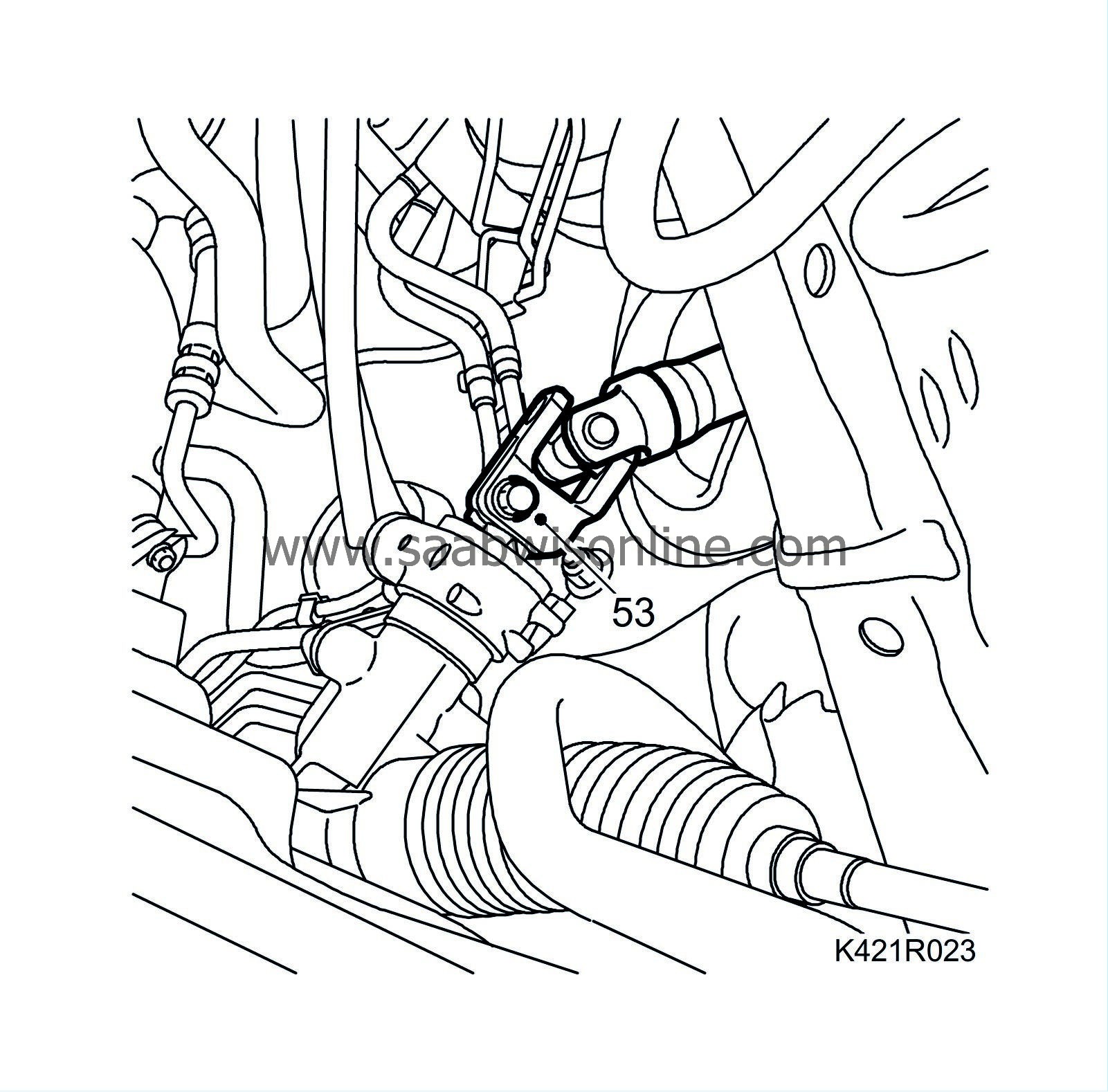
Detach the steering shaft from the steering gear.
|
|
| 54. |
Remove the multigroove belt. Mark the direction of belt rotation.

|
|
| 55. |
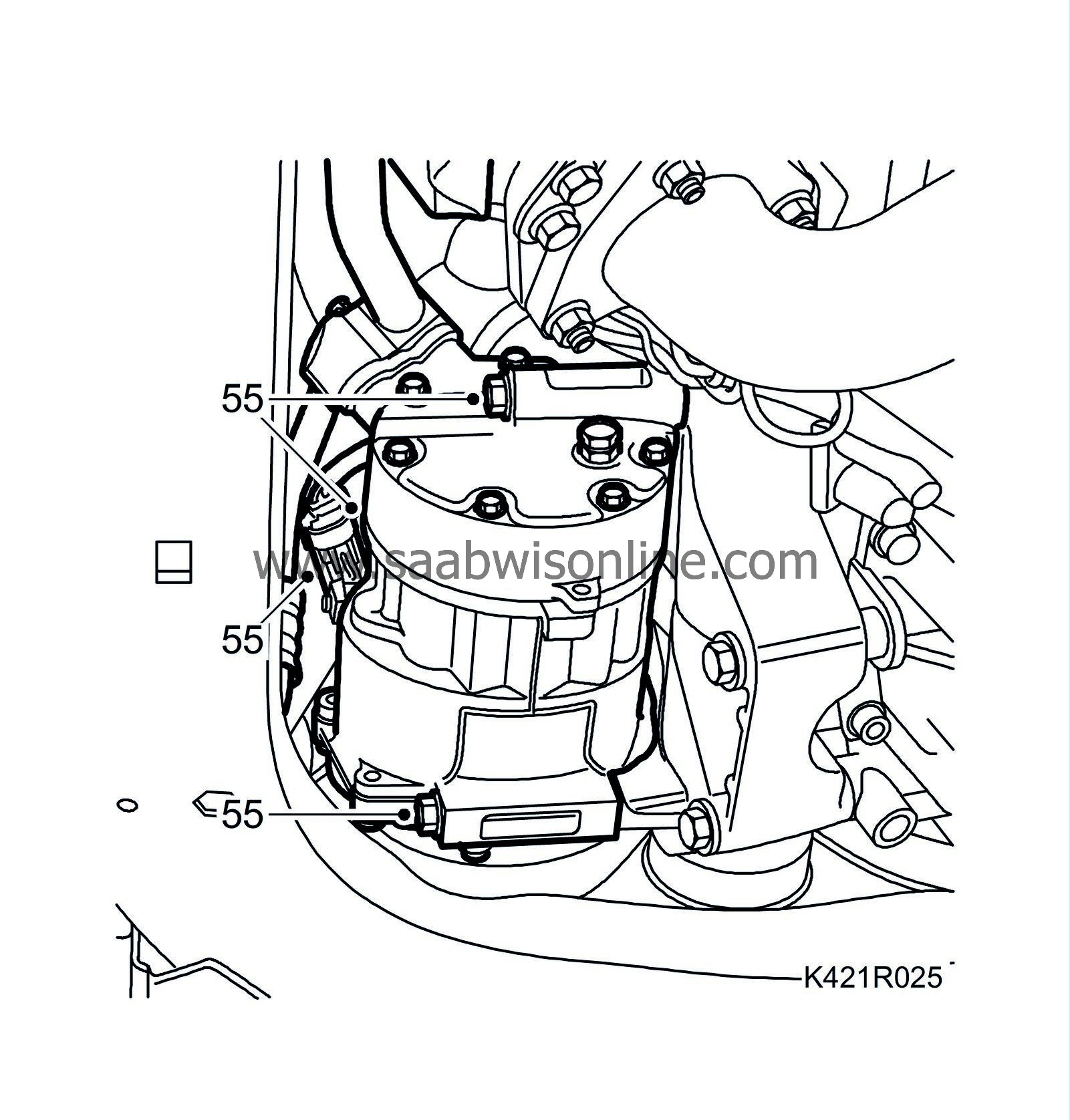
Unplug the A/C compressor connector and remove the A/C compressor retaining bolts.
|
|
| 56. |
Undo the drive shaft centre nuts. Knock loose the drive shafts from the hubs. Use
89 96 951 Puller, drive shaft
or a brass drift with mallet.
|
|
| 57. |
Undo the nuts and the outboard steering links from the steering swivel member with
87 91 287 Puller, 150 mm
.

|
|
| 58. |
Disconnect the lower links of the anti-roll bar. Use a thin wrench in the keys to hold them still.
|
|
| 59. |
Option:
Remove the connector for the headlamp angle sensor and undo the cable from the subframe. Remove the bracket from the suspension arm.
|
|
| 60. |
Undo the lower swivel joints from the steering swivel members and lower the suspension arms.
|
|
| 61. |
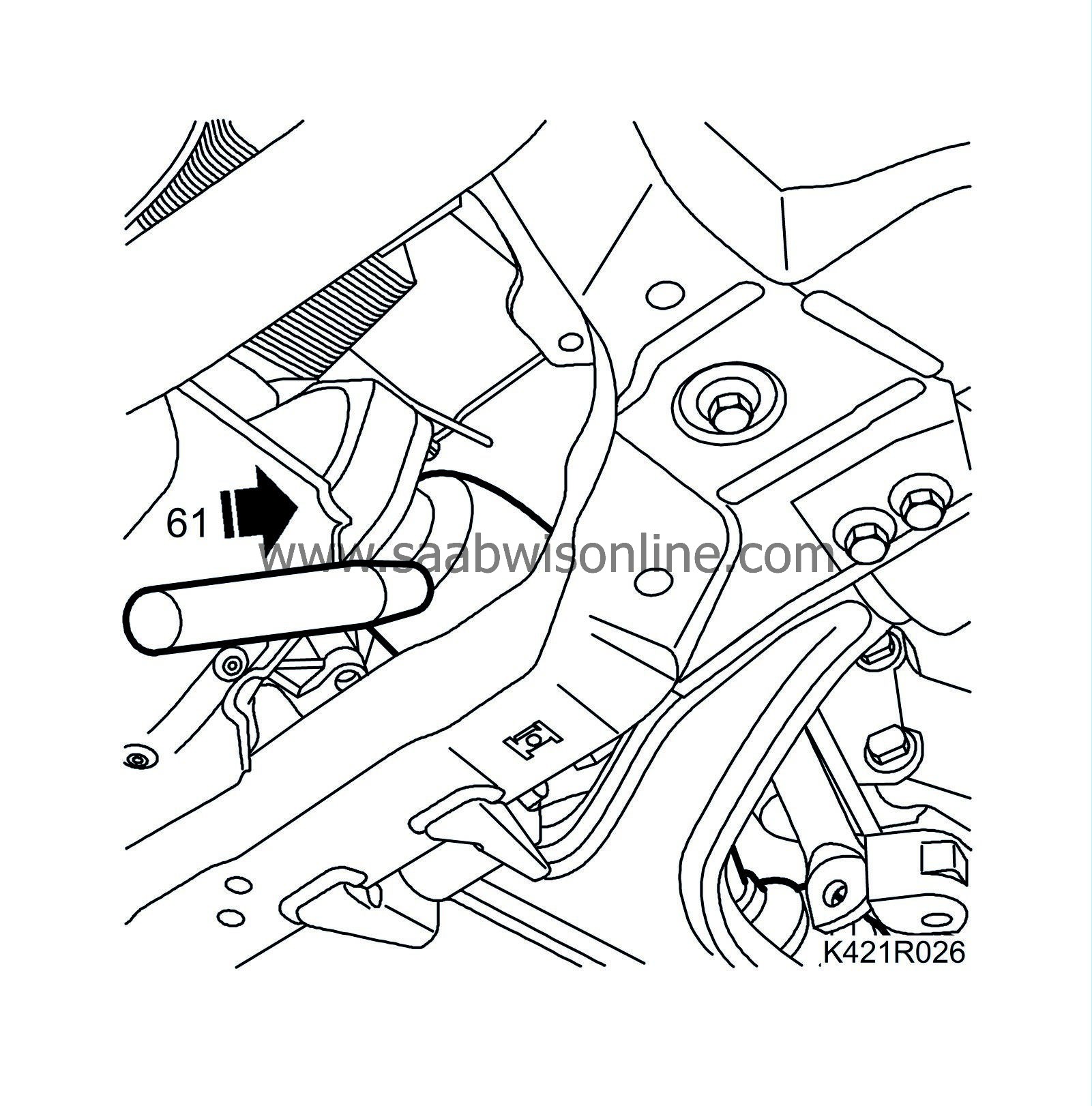
Remove the right-hand drive shaft from the intermediate shaft.
|
|
| 62. |
Remove the intermediate shaft.
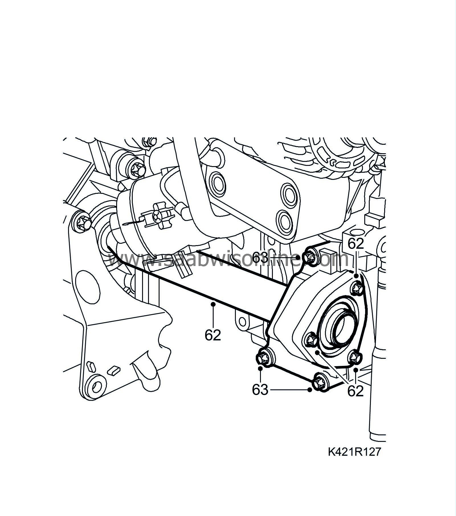
|
|
| 63. |
Remove the intermediate shaft bracket.
|
|
| 64. |
Remove the front exhaust pipe.
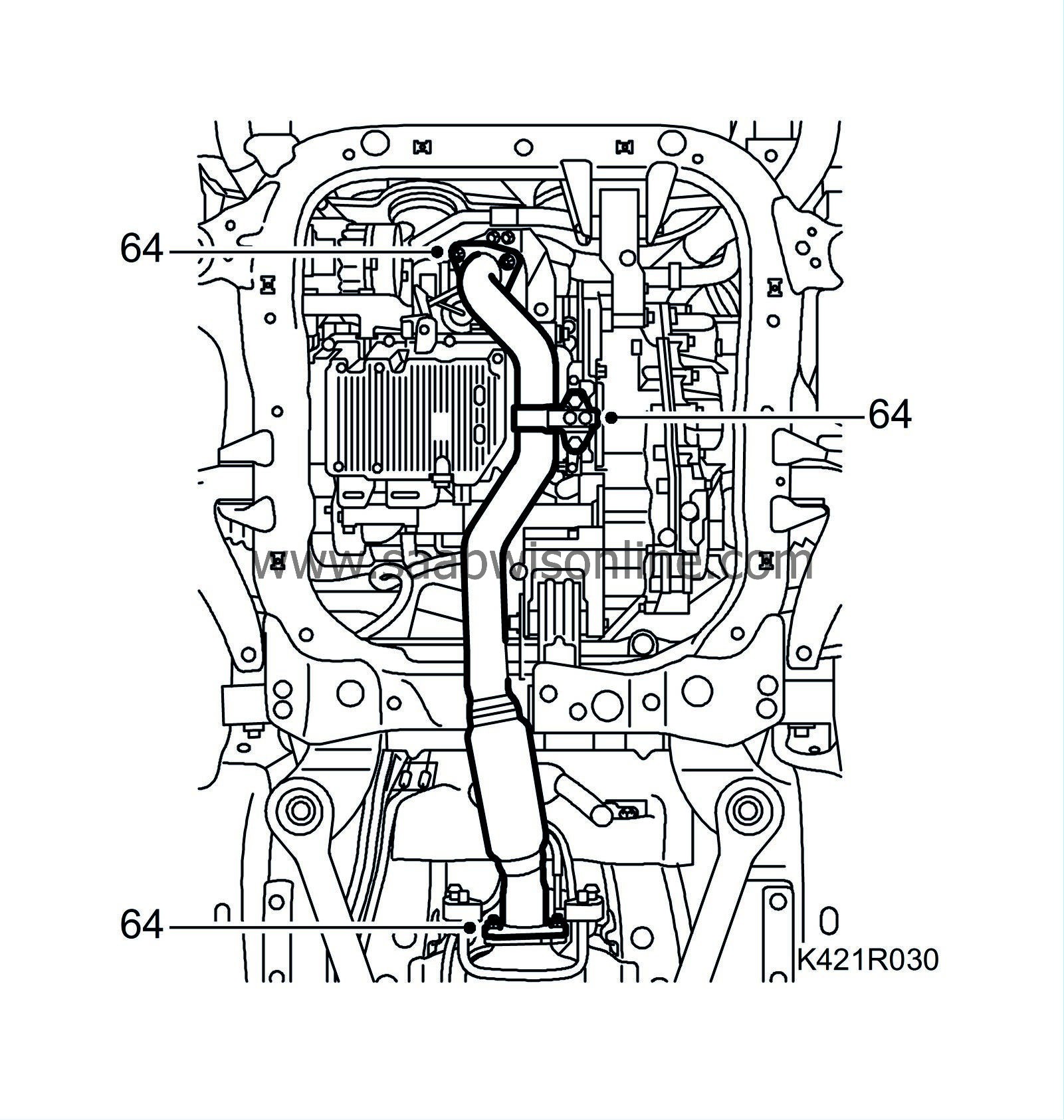
|
|
| 65. |
Fit
KM 6313 Centring fixture, subframe - engine
on the subframe. The bracket is installed in the A/C compressor's retaining bracket. Due to narrow tolerances on the drive shafts, the centring tool must be used to carefully fit the powertrain in against the subframe and body when reinstalled.
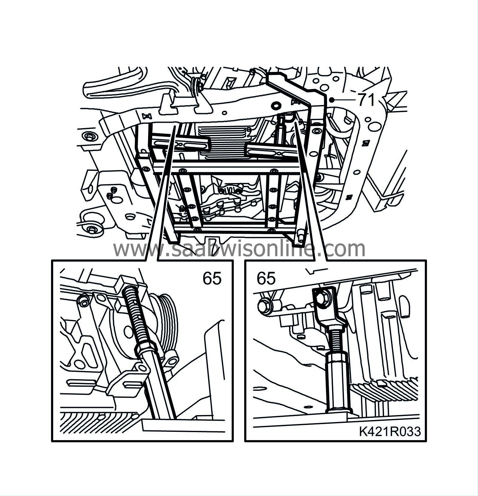
|
|
| 66. |
Lower the car.
|
|
| 67. |
Fit 2 x
83 95 212 Straps
to the radiator member. Lower one strap down around the radiator assembly. Wind an extra time around the A/C compressor to take the strain.

|
|
| 68. |
Remove the right-hand engine pad.

|
|
| 69. |
Remove the left engine pad.
|
|
| 70. |
Raise the car.
|
|
| 71. |
Position
83 96 137 Centring tool, subframe - body
on the trolley lift. Make sure the height adjusting screws 83 95 170 are in their lowermost position.
|
|
| 72. |
Raise the trolley lift slightly so that it is firmly pressed against the subframe. Undo the bolts securing the subframe and subframe stay to the body.
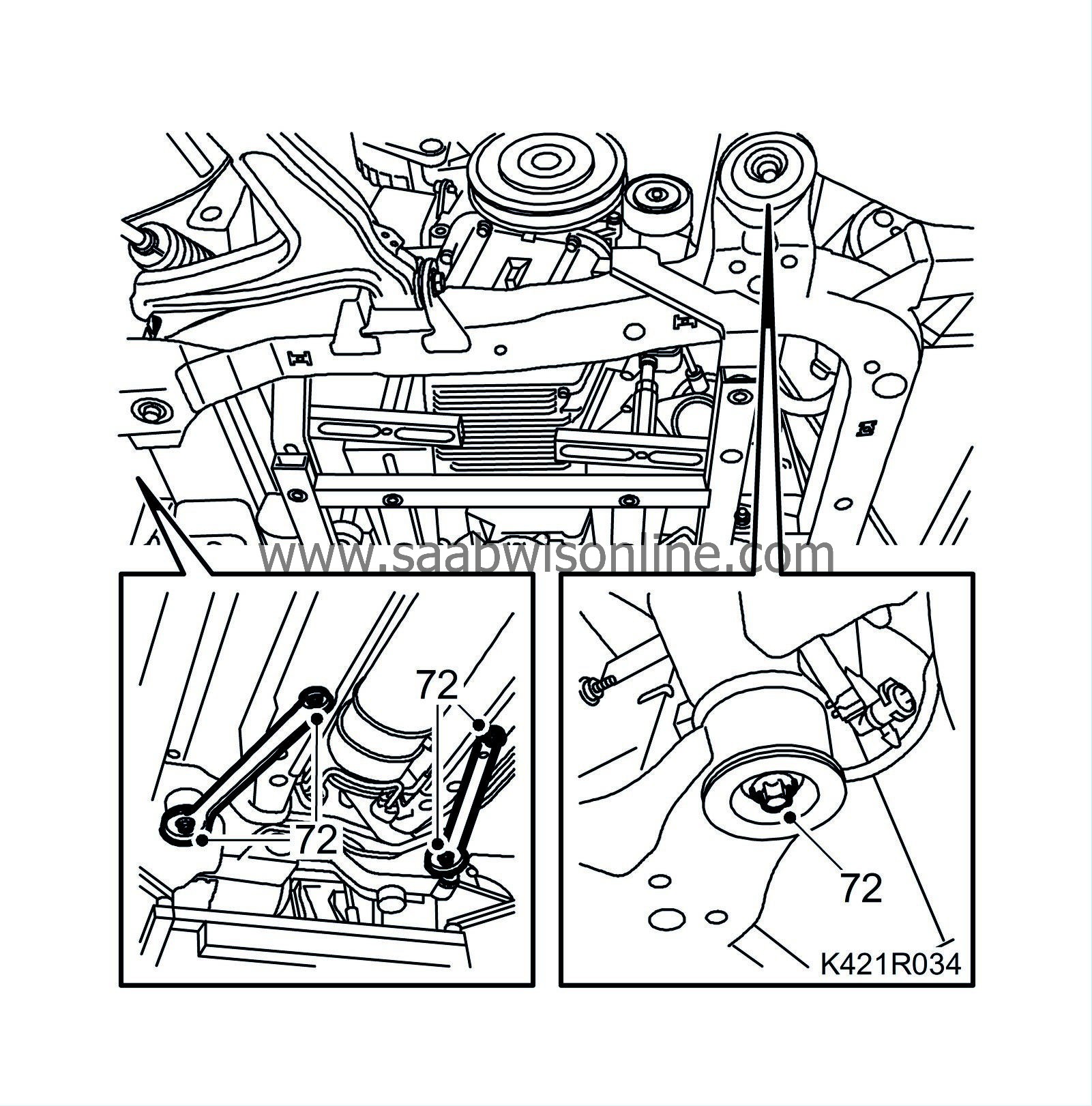
|
|
| 73. |
Carefully lower the power unit on the trolley lift, making sure nothing gets caught or damaged.
|
|

 Warning
