Drive shafts, rear, 4WD
| Drive shafts, rear, 4WD |
| To remove |
| 1. |
Remove the spring. See
Spring, 4WD
.
|
|
| 2. |
Remove the nut from the drive shaft.
|
|
| 3. |
Press in the drive shaft so that it releases from the hub. Use
89 96 951 Drive shaft puller
.
|
|
| 4. |
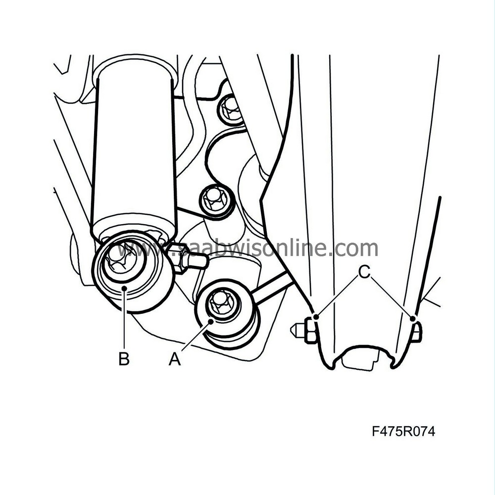
Remove the anti-roll bar link (A) from the steering swivel member. Suspend the anti-roll bar with
83 95 212 Strap
.

|
|
| 5. |
Remove the shock absorber (B) from the steering swivel member.
|
|
| 6. |
Loosen the bolt (C) from the lower link arm a few turns.
|
|
| 7. |
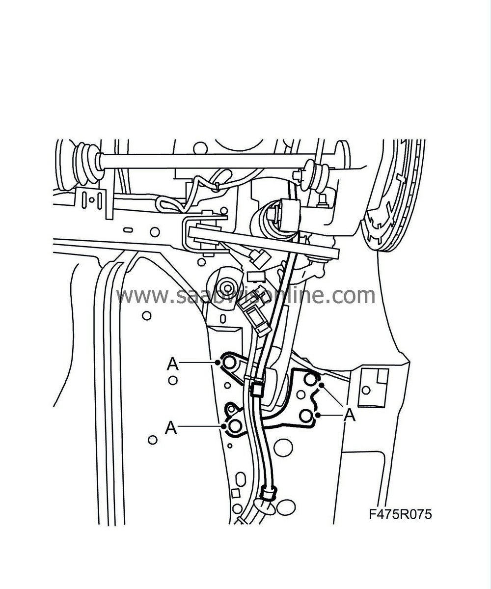
Remove the wheel sensor's wiring harness (A) from the upper suspension arm.

|
|
| 8. |
Remove the upper suspension arm mounting (A) from the subframe.

|
|
| 9. |
Remove the front mounting (C) of the longitudinal link.

|
|
| 10. |
Fold out the steering swivel member (A) and remove the drive shaft universal joint (B) from the wheel hub.

|
|
| 11. |
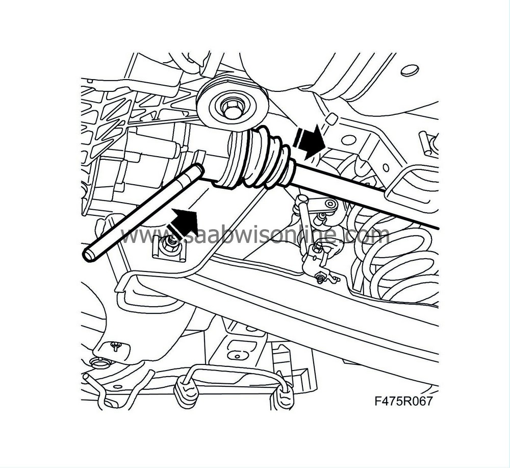
Tap out the drive shaft from the final drive gear with a brass drift and mallet.

|
|||||||||
| 12. |
Remove the drive shaft.

|
|
| To fit |
| 1. |
Fit the drive shaft.
Lubricate the shaft's splines with final drive gear oil. Press in the shaft until the circlip engages. 
|
|
| 2. |
Fold up the steering swivel member (A) and at the same time fit the drive shaft universal joint (B) to the wheel hub and fit the nut.

|
|
| 3. |
Fit the upper suspension arm mounting (A) to the subframe. Do not tighten the bolt.

|
|
| 4. |
Fit the wheel sensor's wiring harness (A) to the upper suspension arm.

|
|
| 5. |
Fit the front mounting (A) of the longitudinal link.
Tightening torque 90 Nm +90° (52 lbf ft +90°) 
|
|
| 6. |
Fit the anti-roll bar link (A) to the steering swivel member and remove the belt tensioner.
Tightening torque 53 Nm (39 lbf ft) 
|
|
| 7. |
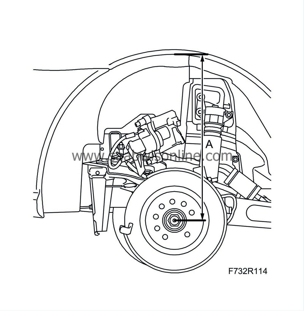
Lift the steering swivel member to normal position 374 mm, 9-3X 390 mm (A) between the centre of the drive shaft and the edge of the wing.

|
|
| 8. |
Fit the shock absorber (B) to the steering swivel member.
Tightening torque 148 Nm +90°(109 lbf ft + 90°) 
|
|
| 9. |
Tighten the bolt for the lower suspension arm mounting (A) to the steering swivel member.
Tightening torque 75 Nm +90°(55 lbf ft + 90°) 
|
|
| 10. |
Fit the nut (A) for the upper suspension arm mounting to the subframe.
Tightening torque 75 Nm +90°(55 lbf ft + 90°) 
|
|
| 11. |
Check/adjust the oil level in the final drive gear, see Checking/changing the oil in the limited slip differential.
|
|
| 12. |
Remove the centre emblem from the wheel rim.
|
|
| 13. |
Fit the spring. See
Spring, 4WD.
|
|
| 14. |
Lower the car to the floor.
|
|
| 15. |
Tighten the hub centre-nut.
Tightening torque 230 Nm (170 lbf ft) |
|
| 16. |
Fit the centre emblem to the wheel rim.
|
|

 Warning

