Solenoid valve 1, 2, 3, soft top (647a, b, c)
| Solenoid valve 1, 2, 3, soft top (647a, b, c) |
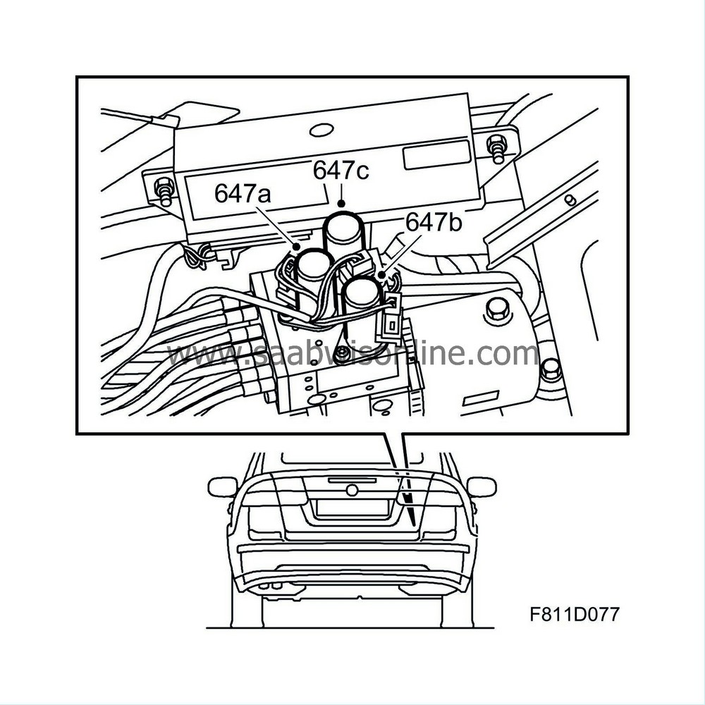
| Location |
Solenoid valve 1, soft top (647a)
Solenoid valve 2, soft top (647b)
Solenoid valve 3, soft top (647c)

| Main task |
The valves control the oil flow to the hydraulic cylinders.

| Type |
Electrically operated solenoid valve.
Technical data
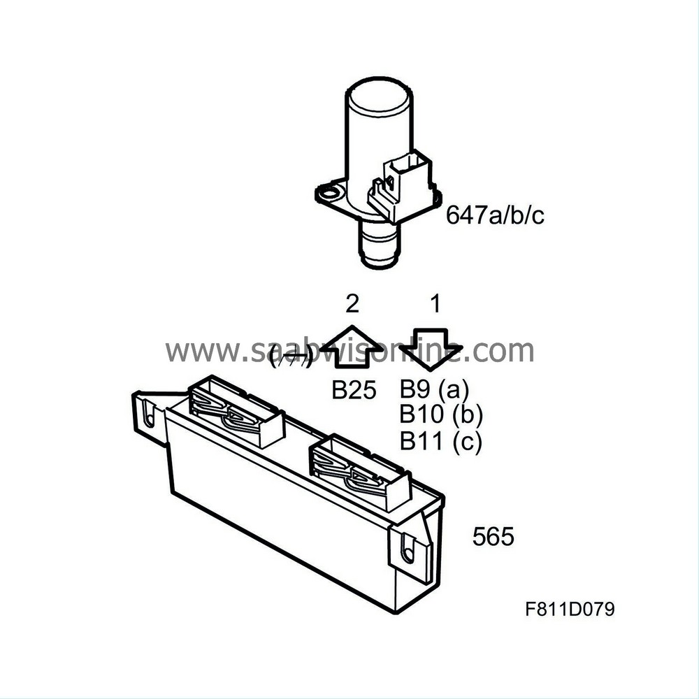
| Connection |
| Pin No. | Signal type | Description |
| 1 | Control voltage | The STC control module activates each valve by feeding pin 1 with B+ |
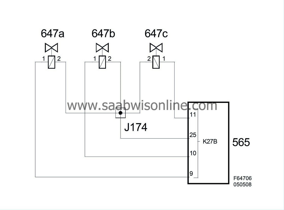
| 2 | Ground | All the valves are grounded through pin 25 on the STC control module |

The valve is grounded on pin 2 and is activated by the STC control module putting B+ on pin 1.
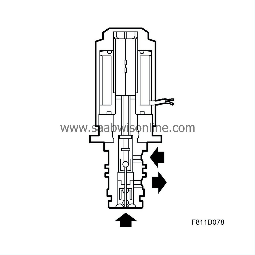
Every valve has three connections.
| • |
Oil pump output pressure
|
|
| • |
Oil pressure to the hydraulic cylinder
|
|
| • |
Oil return to the reservoir
|
|
The valves have two positions: "Active" and "Inactive".
When a valve is active the pump output is connected to the cylinder . When a valve is inactive the pump output is connected to the return line to the reservoir.
Diagram


