Cylinder head
| Cylinder head |
| To remove |
| 1. |
Apply wing covers and remove the battery cover and the negative battery cable.
|
|
| 2. |
Open the cap on the expansion tank.
|
|
| 3. |
Unplug the oxygen sensors and carefully take down the cables.

|
|||||||||
| 4. |
Remove the heat shield over the turbocharger.
|
|
| 5. |
Undo the turbocharger oil delivery pipe.

|
|
| 6. |
Remove the nuts for the catalytic converter connection with the turbocharger.
|
||||||||||
| 7. |
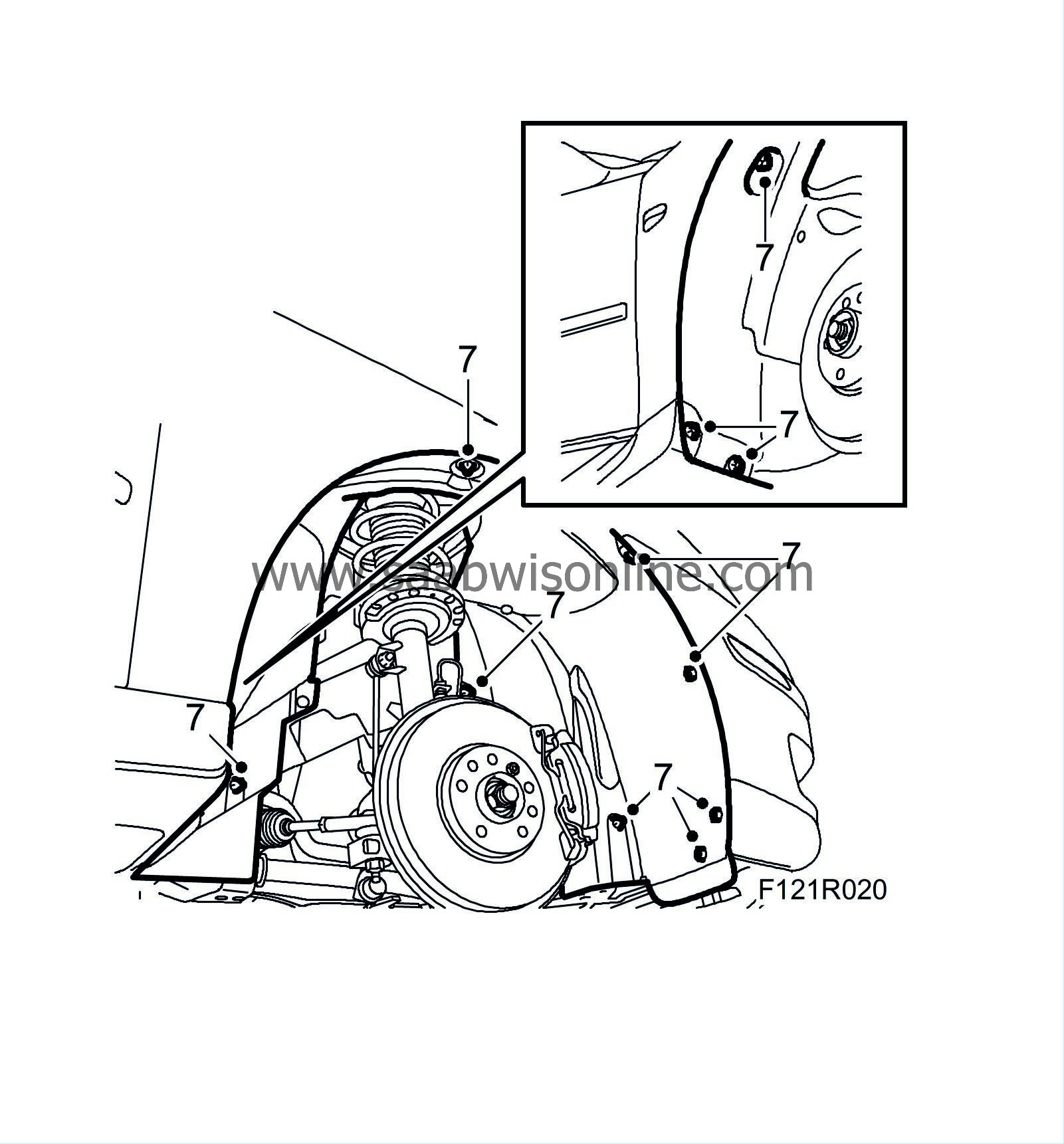
Raise the car and remove the front right wheel and right wing liner.
|
|
| 8. |
Disconnect and bend aside one side of the lower spoiler shield.
CV:
Remove the front subframe chassis reinforcement.

|
|
| 9. |
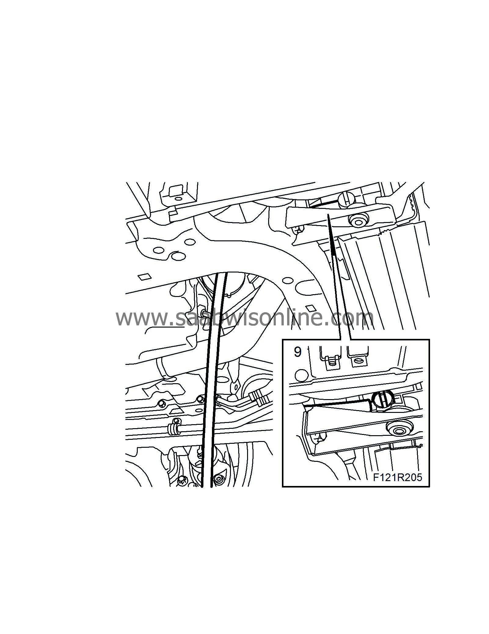
Place a receptacle under the car, connect a hose to the radiator and drain the coolant.
|
|
| 10. |
Remove the lower turbocharger pressure pipe.

|
|
| 11. |
Undo the catalytic converter bracket from the cylinder block.
|
|
| 12. |
Use protective goggles. Place a receptacle under the car, connect a hose and open the cock on the coolant pump to drain the remaining coolant.

|
|
| 13. |
Close the cock.
Tightening torque 20 Nm (15 lbf ft) |
|
| 14. |
Undo the turbocharger coolant pipe.
|
|
| 15. |
Remove the stay between the exhaust manifold and the cylinder block.
|
|
| 16. |
Remove the oil return pipe from the turbocharger.
|
||||||||||
| 17. |
Remove the stay between the intake manifold and the cylinder block.

|
|
| 18. |
Disconnect the starter motor positive cable.
|
|
| 19. |
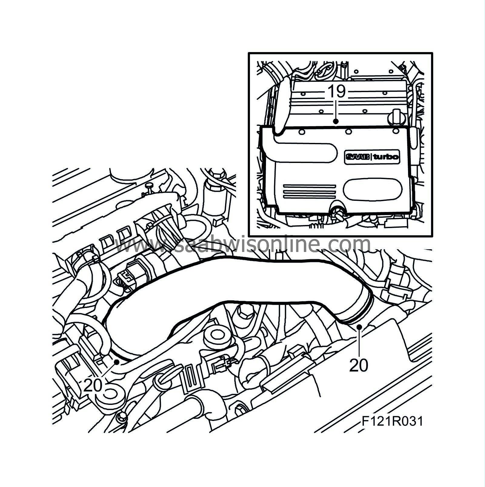
Lower the car and remove the upper engine cover.
|
|
| 20. |
Remove the turbocharger delivery hose from the throttle body and the turbo delivery pipe
|
|
| 21. |
Detach the hoses and remove the turbo inlet pipe. Unplug the mass air flow sensor connector. Plug the turbo inlet.

|
|
| 23. |
Release any pressure in the fuel system by carefully pressing the service valve needle. Collect any fuel spill. Detach both fuel lines from the fuel rail while gripping the lower nut. Plug the fuel lines. Use
82 92 948 Plugs, A/C system assy
.

|
|
| 24. |
Disconnect the quick-release coupling for the breather line and detach the fuel lines and bleeder lines from the clips on the camshaft cover. Bend up the breather hose from the intake manifold and place it on the camshaft cover.
|
|
| 25. |
Remove cover over ignition coils.

|
|
| 26. |
Unplug ignition coil connectors. Unplug connector to turbocharger solenoid valve and undo cable clips.

|
|
| 27. |
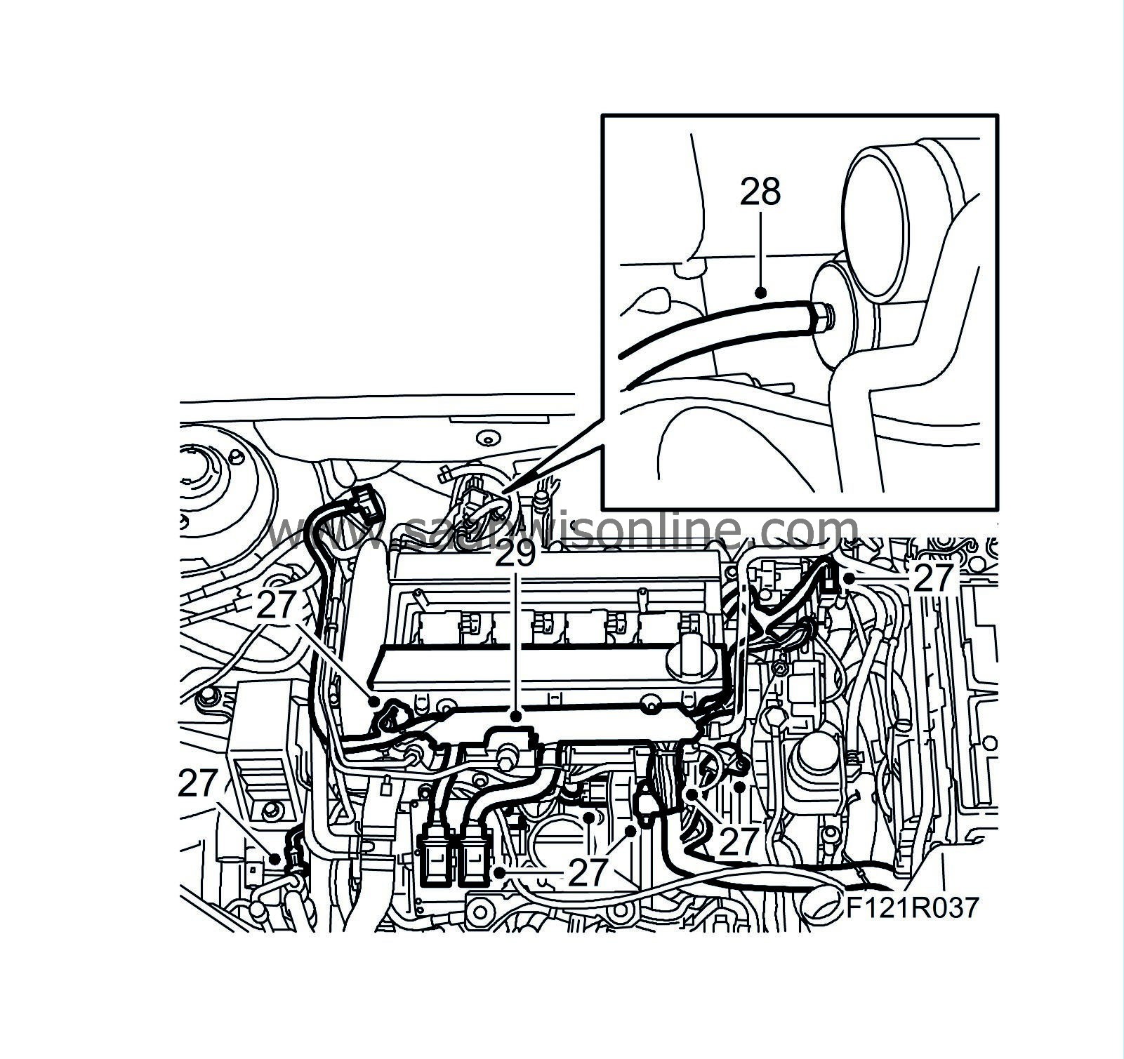
Unplug A/C pressure sensor connector, connector to coolant temperature sensor, engine control module, bypass valve solenoid valve, throttle body, intake manifold pressure sensor, atmospheric pressure sensor, IDM module, oil pressure sensor and ground cable on engine control module.
|
|
| 28. |
Detach hose from turbocharger wastegate and solenoid valve.
|
|
| 29. |
Detach the cable duct and bracket from the camshaft cover. Move away the engine wiring harness.
|
|
| 30. |
Remove wiring harness nuts from oil filter housing and intake manifold and detach the wiring harness.

|
|
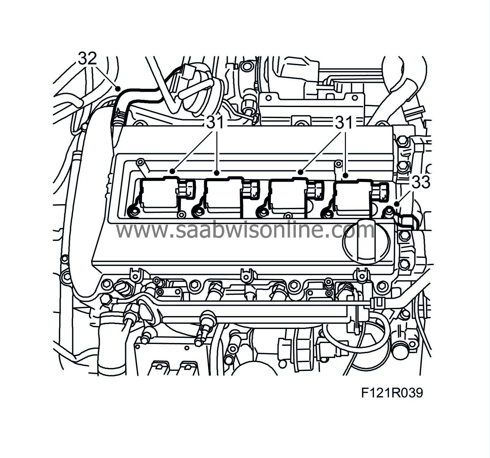
| 31. |
Remove the ignition coils.
|
|
| 32. |
Detach crankcase ventilation hose from camshaft cover.
|
|
| 33. |
Undo ground cable from camshaft cover.
|
|
| 34. |
Remove the camshaft cover.

|
|
| 35. |
Zero the engine by turning the crankshaft clockwise until the mark on the crankshaft pulley agrees with the mark on the timing cover, cyl. 1 cams on intake and exhaust camshaft must be pointing in/up.

|
|
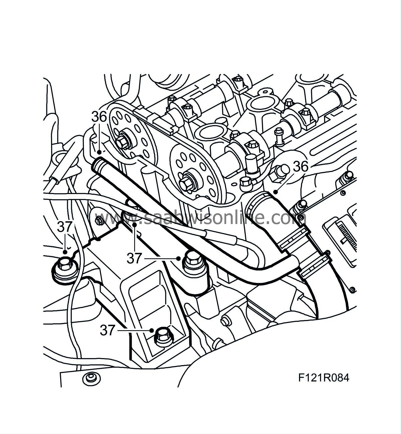
| 36. |
Detach coolant hose from pipe and cylinder head.
|
|
| 37. |
Place a jack with wood block under the oil sump and relieve the right-hand engine pad. Remove the right-hand engine mounting.
|
|
| 38. |
Detach coolant hose from pipe on cylinder head. Detach vacuum hose from brake servo.

|
|
| 39. |
Cars with secondary air injection pump
: Remove pump pipe and upper retaining bolt from intake manifold.
|
|
| 40. |
Undo power steering pump.
|
|
| 41. |
Remove bolt for dipstick tube. Unplug the connector and detach it from the pipe.

|
|
| 42. |
Remove the chain tensioner. Use
83 96 129 Oil filter tool.

|
|
| 43. |
Undo the camshaft sprockets. Grip the respective camshaft on its flats.
|
|
| 44. |
Tie a cable tie around the exhaust camshaft sprocket and chain, remove the camshaft sprockets and lower the exhaust camshaft sprocket with chain.
|
|
| 45. |
Remove the plug from the cylinder head.
|
|
| 46. |
Remove the bolt for the chain guide on the intake side, move away the guide and refit the bolt.
|
|
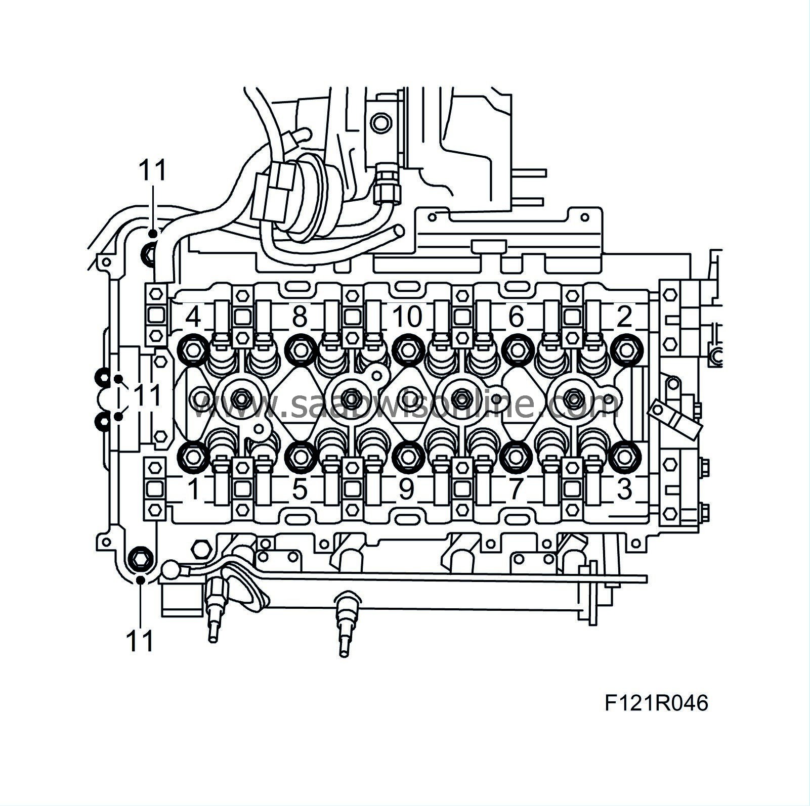
| 47. |
Remove the cylinder head in the order shown in the illustration.
|
|
| To fit |
| 1. |
Carefully blow the bolt hole clean in the cylinder block with compressed air.
|
|
| 2. |
Clean the cylinder bore, cylinder head and cylinder block sealing surfaces from any gasket remains. Check with a steel rule that the cylinder head and cylinder block are flat and the sealing surfaces are not damaged.
|
|
| 3. |
Check the marks on the pulley and timing cover to make sure the engine is zeroed.
|
|
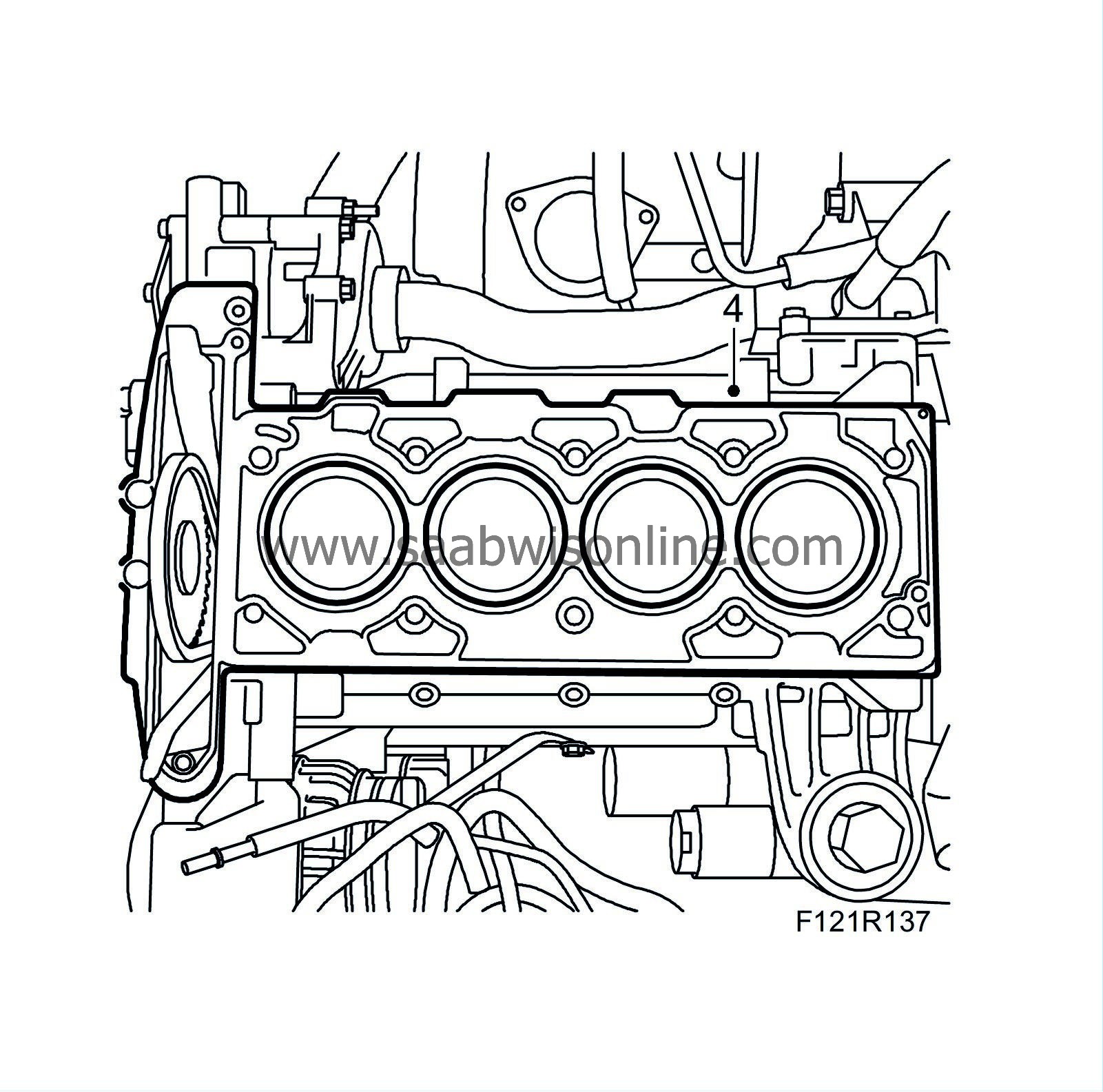
| 4. |
Place a new gasket on the cylinder block. Raise the sprocket and tighten the chain guides together in order to get the cylinder head in place.
|
|
| 5. |
Remove the exhaust camshaft and intake camshaft bearing cap no. 2. Fit
EN-48368 Adjustment tool, camshaft (210 hp)
or
EN-48366 Adjustment tool, camshaft (150 - 175 hp)
onto the camshafts.
Tightening torque 10 Nm (7 lbf ft) 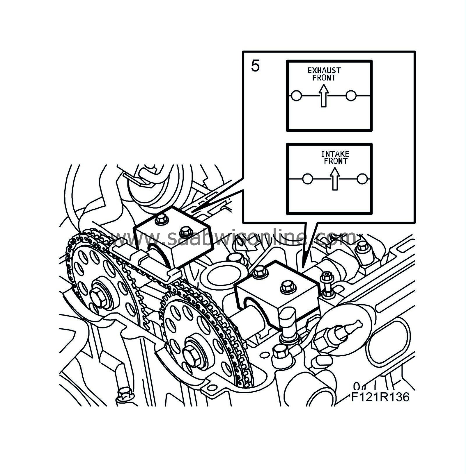
|
|
| 6. |
Fit the cylinder head according to the order shown in the illustration. Insert the bolts carefully. The threads in the cylinder block can be damaged if they are dropped rapidly.
Tightening torque step 1: 30 Nm (22 lbf ft) Tightening torque, step 2: 150° Tightening torque, step 3: 15° Tightening torque, bolts for timing section, 35 Nm (26 lbf ft) 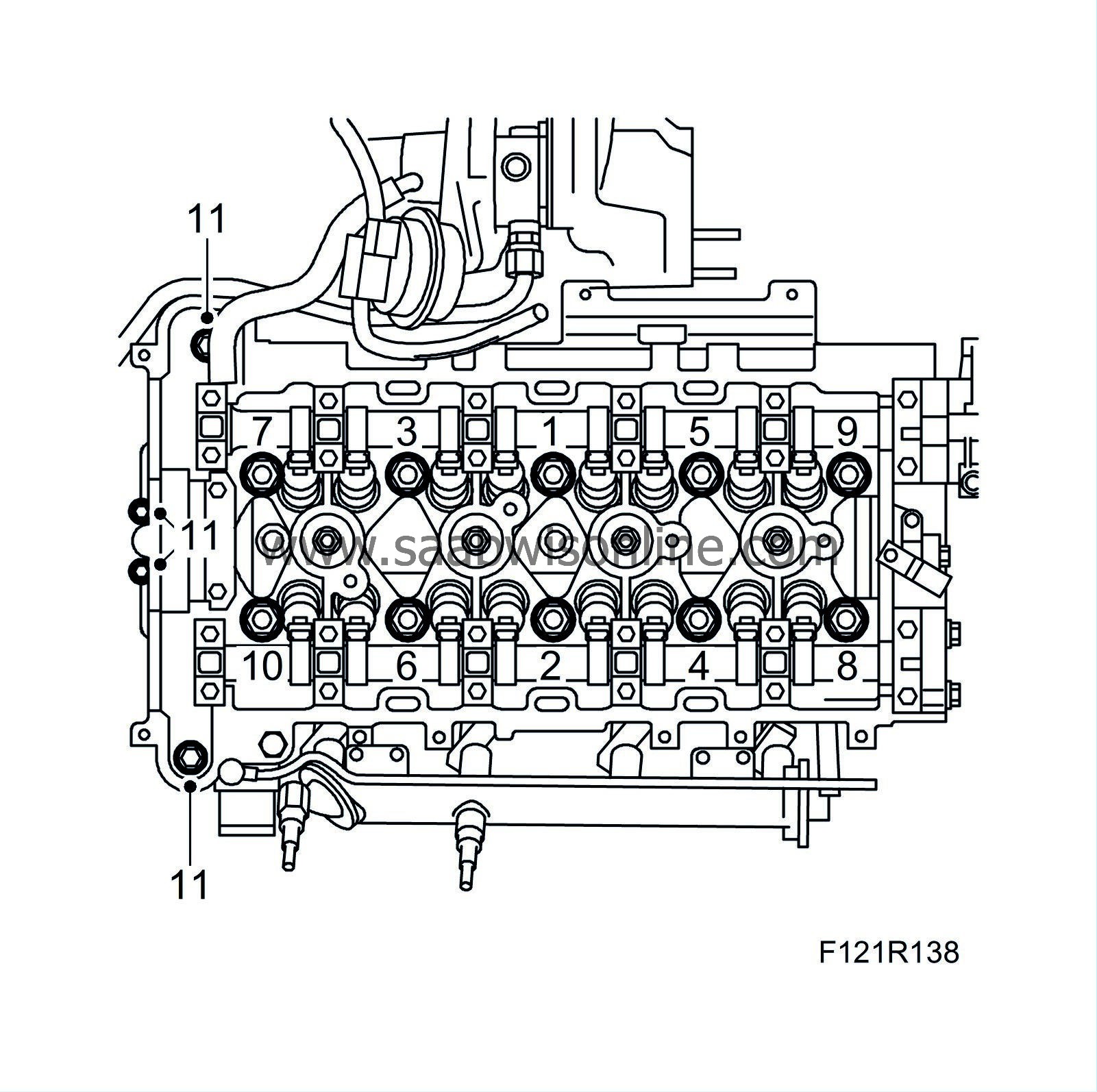
|
|
| 7. |
Remove the bolt for the chain guide. Move back the guide and fit the bolt.
Tightening torque 10 Nm (7 lbf ft) 
|
|
| 8. |
Fit the plug in the cylinder head.
Tightening torque 25 Nm (18 lbf ft) |
|
| 9. |
Fit the sprocket on the exhaust camshaft and intake camshaft without tightening. Check that the engine is zeroed.
|
|
| 10. |
Fit the chain guide "zeroed". The groove on the end of the chain tensioner must be vertical when fitting. See
Timing chain tensioner
- fitting. Use
83 96 129 Oil filter tool, and chain tensioner camshaft drive
Tightening torque 75 Nm (55 lbf ft) |
|||||||
| 11. |
Tighten the camshaft sprockets. Grip the respective camshaft on its flats. Remove the cable tie.
Tightening torque 85 Nm + 30° (63 lbf ft +30°) |
|
| 12. |
Remove the camshaft adjustment tool and fit the camshaft caps.
Tightening torque 8 Nm (6 lbf ft) |
|
| 13. |
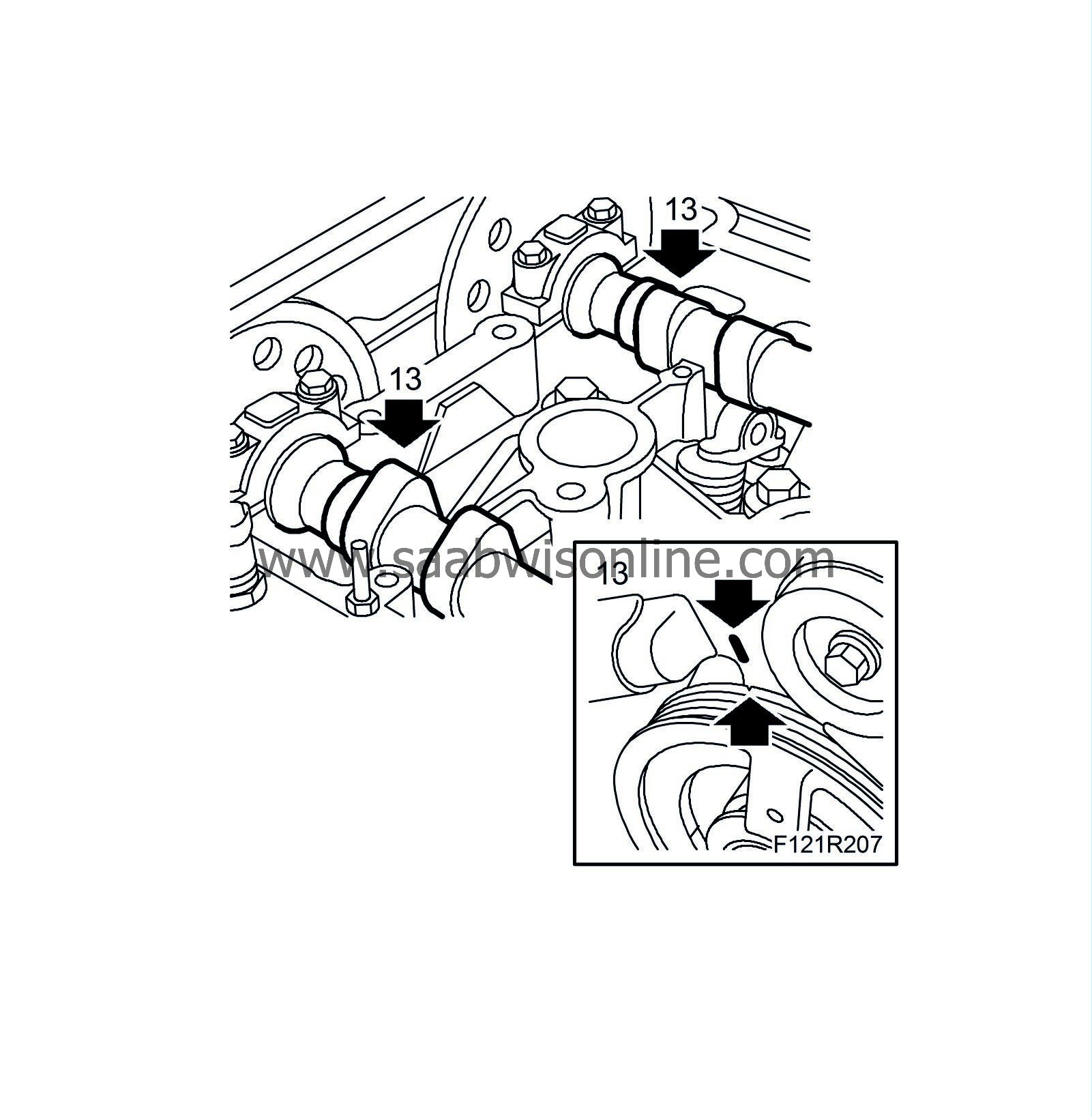
Turn over the engine 2 revolutions and zero so that the belt pulley and the timing cover marks align. Remove bearing caps no. 2 and no. 7 and fit
EN-48368 Camshaft setting tool (210 hp)
or
EN-48366 Camshaft setting tool (150 - 175 hp)
again to check that the camshaft setting is correct. Remove the setting tools and fit the bearing caps.
|
|
| 14. |
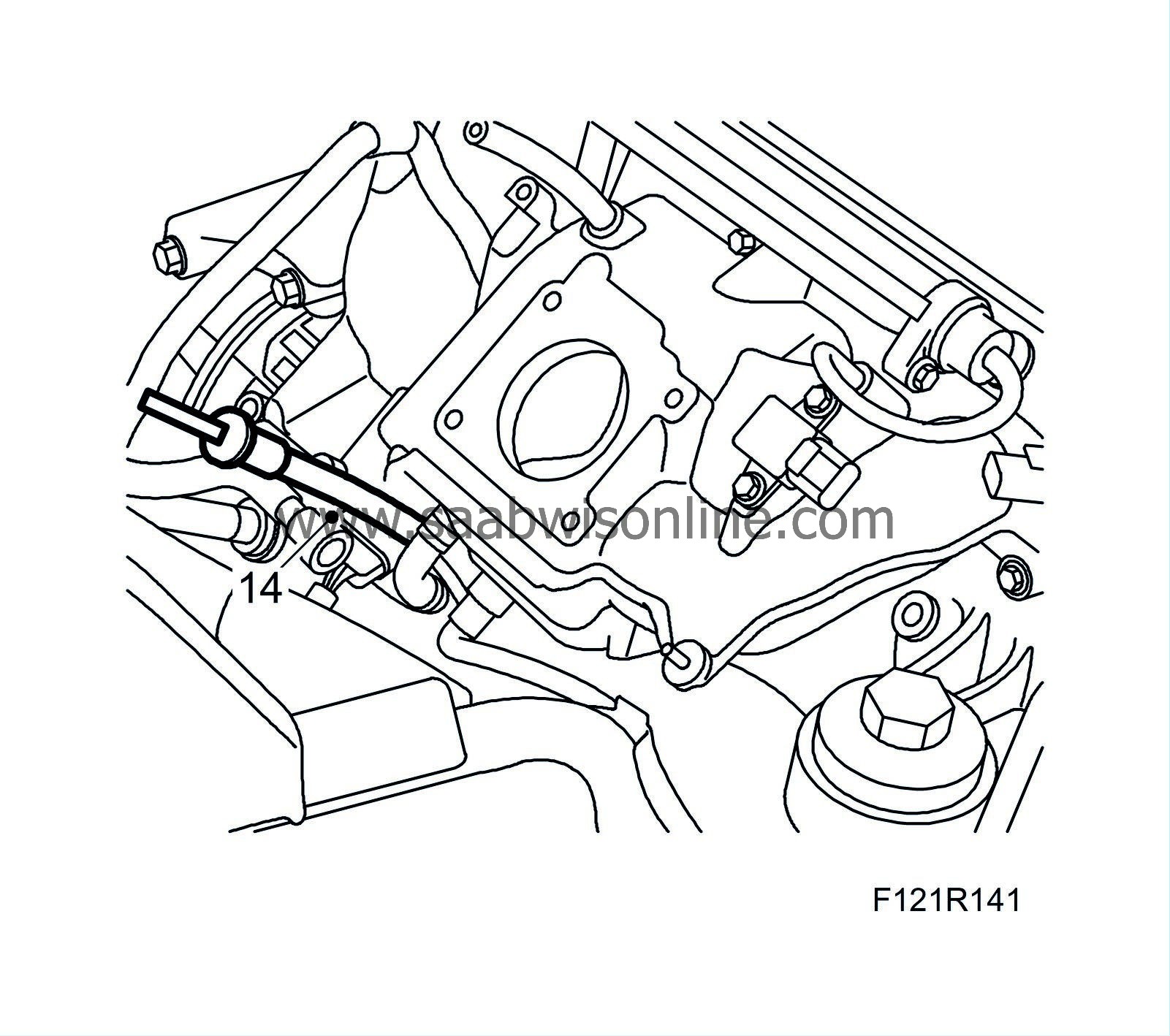
Fit the screw for the dipstick. Plug in the connector and fit the connector to the tube.
|
|
| 15. |
Cars with secondary air injection pump
: Fit the pump's top retaining bolt. Fit the pipe between the pump and the valve.
|
|
| 16. |
Fit the power steering pump with new seal.
Tightening torque 22 Nm (16 lbf ft) 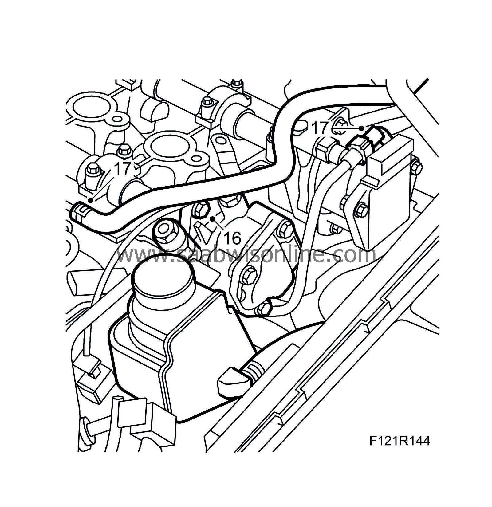
|
|
| 17. |
Connect coolant hose to pipe on cylinder head. Attach vacuum hose to brake servo.
|
|
| 18. |
Fit the right-hand engine pad.
Tightening torque, bolts to body 40 Nm + 60° (30 lbf ft + 60 °) Tightening torque, bolts to bracket 70 Nm + 60° (52 lbf ft + 60 °) 
|
|
| 19. |
Fit coolant hose to pipe on cylinder head.
|
|
| 20. |
Fit the camshaft cover with new seal.
Tightening torque 10 Nm (7 lbf ft) 
|
|
| 21. |
Connect the ground cable to the camshaft cover.
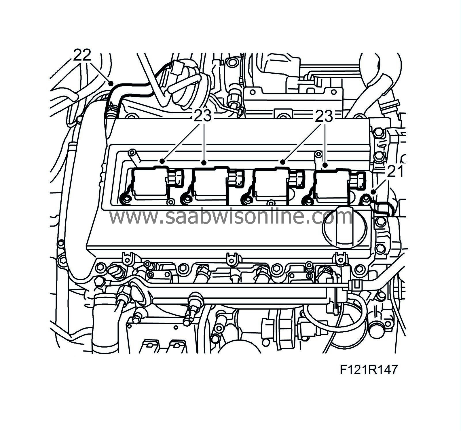
|
|
| 22. |
Connect the crankcase ventilation hose to the camshaft cover.
|
|
| 23. |
Fit the ignition coils.
Tightening torque 8 Nm (6 lbf ft) |
|
| 24. |
Fit the wiring harness to the intake manifold and oil filter housing.
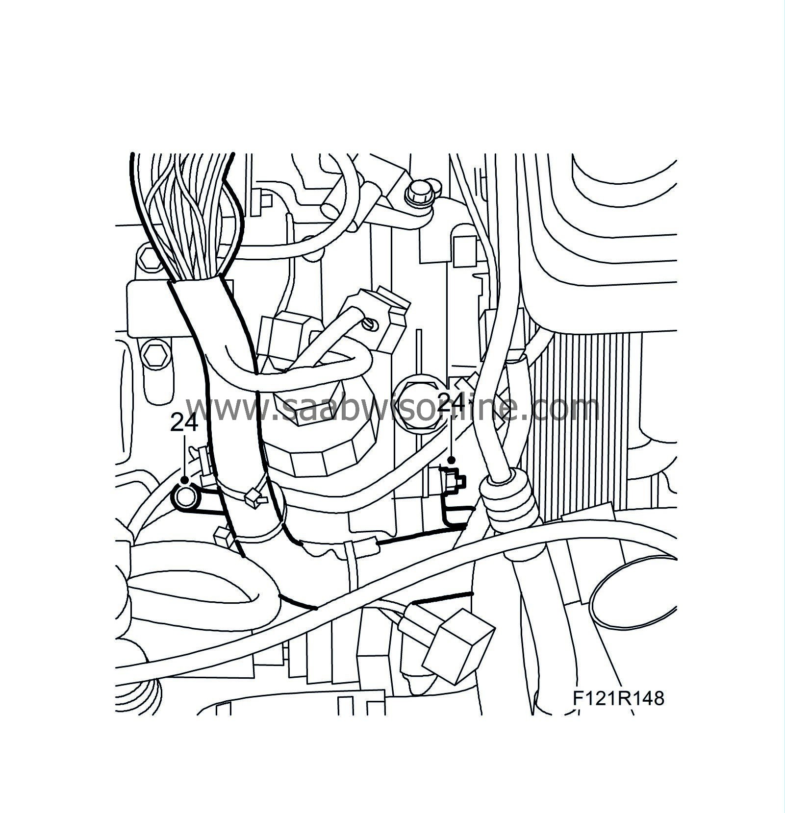
|
|
| 25. |
Fit the cable duct and bracket to the camshaft cover.

|
|
| 26. |
Connect hose to turbocharger wastegate and solenoid valve.
|
|
| 27. |
Plug in A/C pressure sensor connector, connector to coolant temperature sensor, engine control module, bypass valve solenoid valve, throttle body, intake manifold pressure sensor, atmospheric pressure sensor, IDM module, oil pressure sensor and ground cable on engine control module.
|
|
| 28. |
Plug in the ignition coil connectors. Make sure the cable is lying correctly and does not get pinched by the cover. Plug connector to turbocharger solenoid valve and cable clips.

|
|
| 29. |
Fit the cover over the ignition coils.
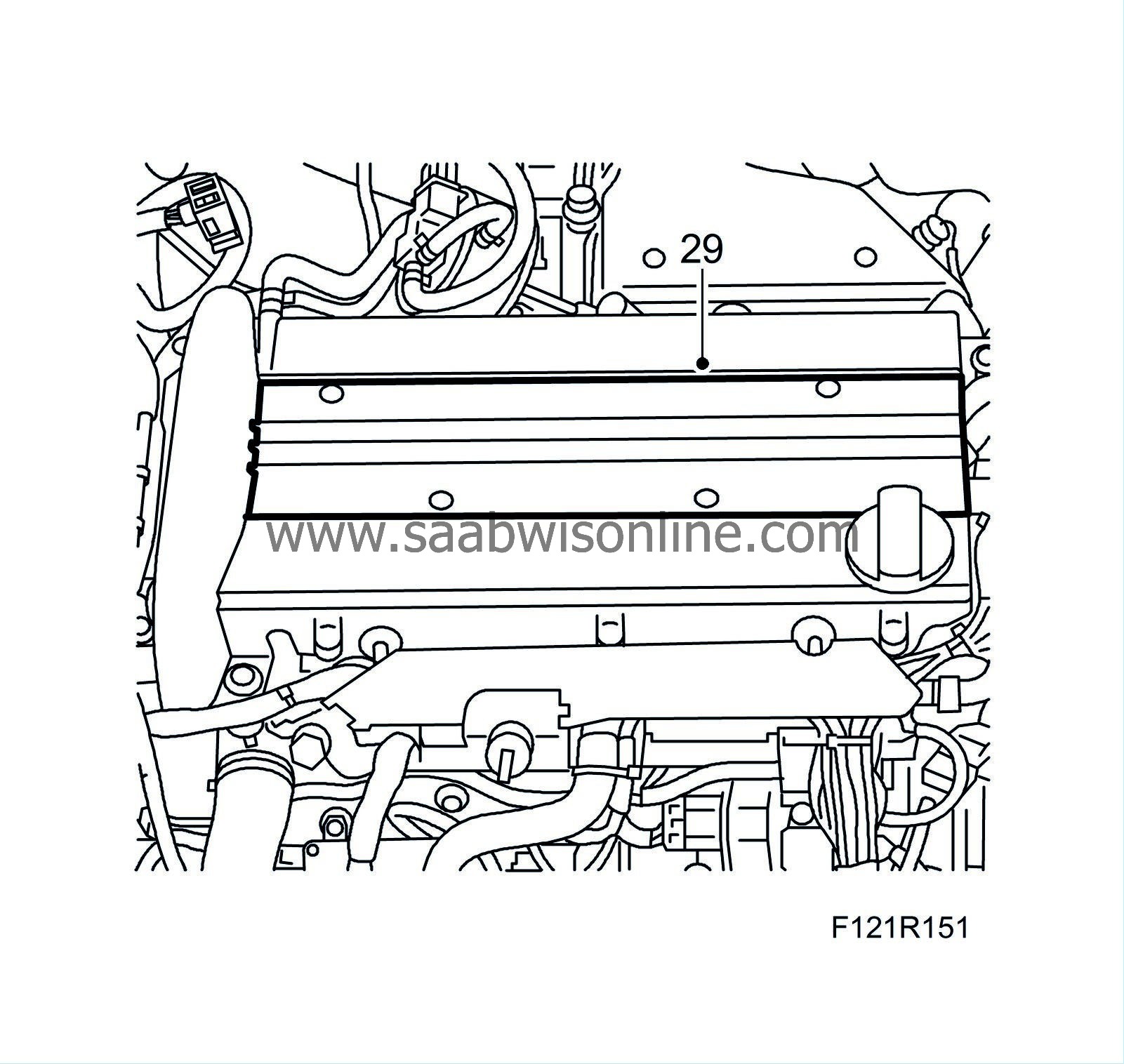
|
|
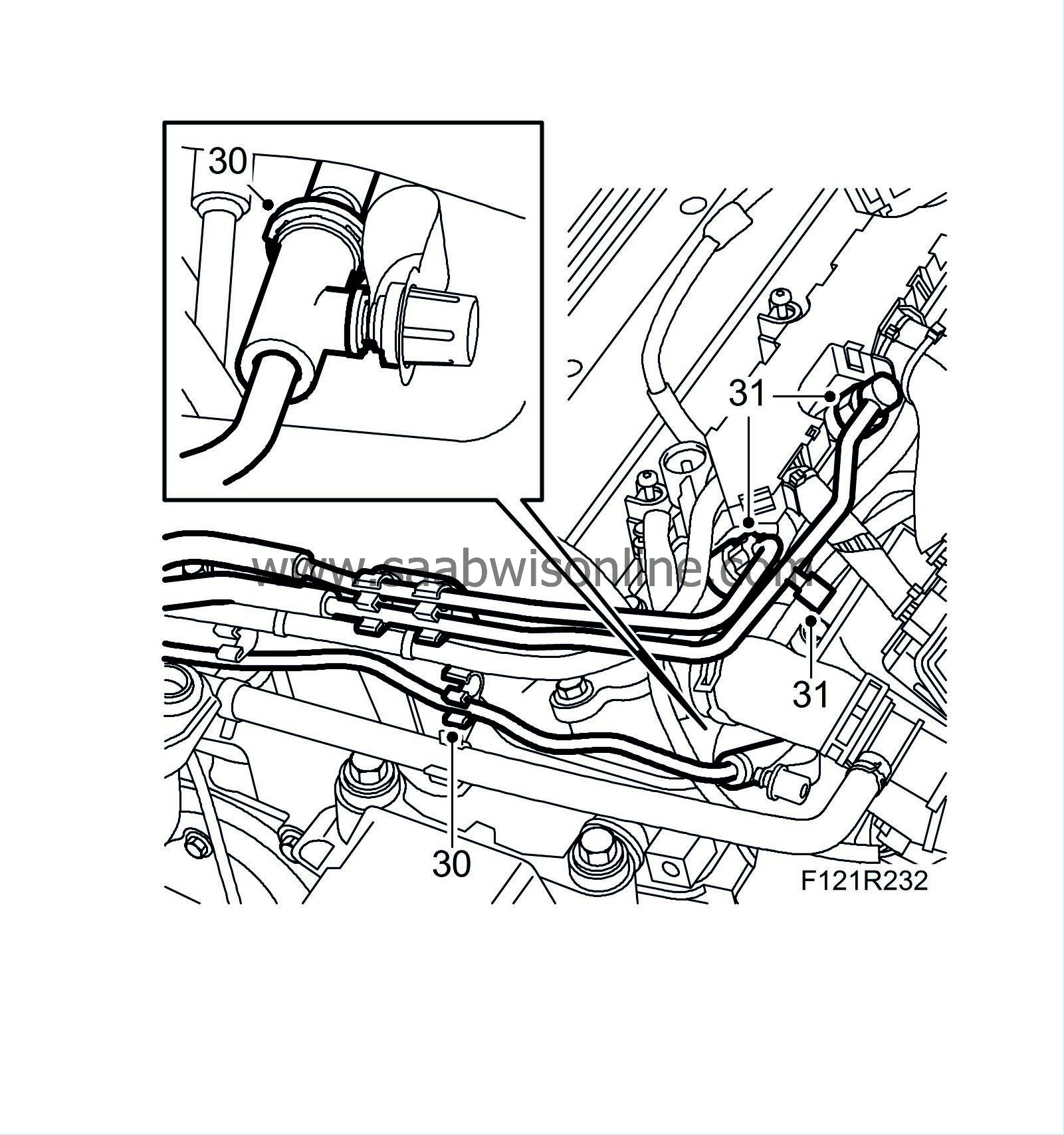
| 30. |
Press the fuel lines and breather lines into the clips on the camshaft cover. Connect the quick release coupling for the breather line.
|
|
| 31. |
Connect both fuel lines to the fuel rail while gripping the lower nut. Use new seals.
Tightening torque 10 Nm (7 lbf ft) |
|
| 32. |
Fit the air cleaner casing and connect the intake hose. Fit the air filter.

|
||||||||||
| 33. |
Connect air cleaner casing cover. Plug in the mass air flow sensor connector and fit the turbo inlet pipe. Attach hoses to turbo inlet pipe.

|
|
| 34. |
Fit the turbocharger delivery hose to the throttle body and the turbo delivery pipe.

|
|
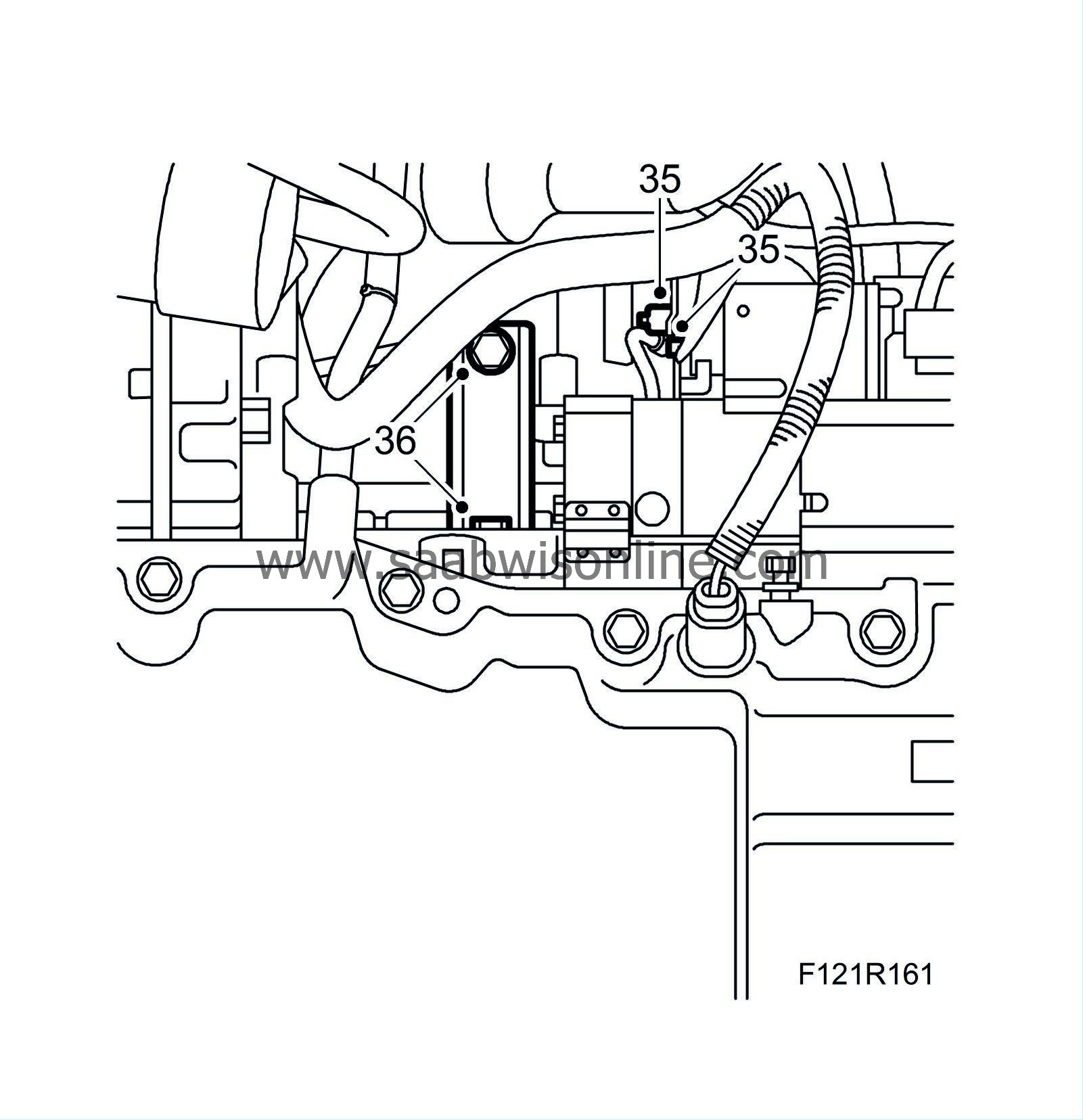
| 35. |
Connect the starter motor positive cable.
|
|
| 36. |
Fit the stay between the intake manifold and the cylinder block.
Tightening torque 22 Nm (16 lbf ft) |
|
| 37. |
Fit the oil return pipe to the turbo. Use a new gasket and new O-ring.
Tightening torque 15 Nm (11 lbf ft) 
|
|
| 38. |
Fit the stay between the exhaust manifold and the cylinder block.
Tightening torque 22 Nm (16 lbf ft) |
|
| 39. |
Fit the turbo coolant pipe with new seals.
Tightening torque 40 Nm (30 lbf ft). |
|
| 40. |
Lower the car and fit the catalytic converter with new nuts so that it is butt against the turbo. Use
30 20 971 Screw-thread paste
on the studs.
Tightening torque 25 Nm (18 lbf ft) 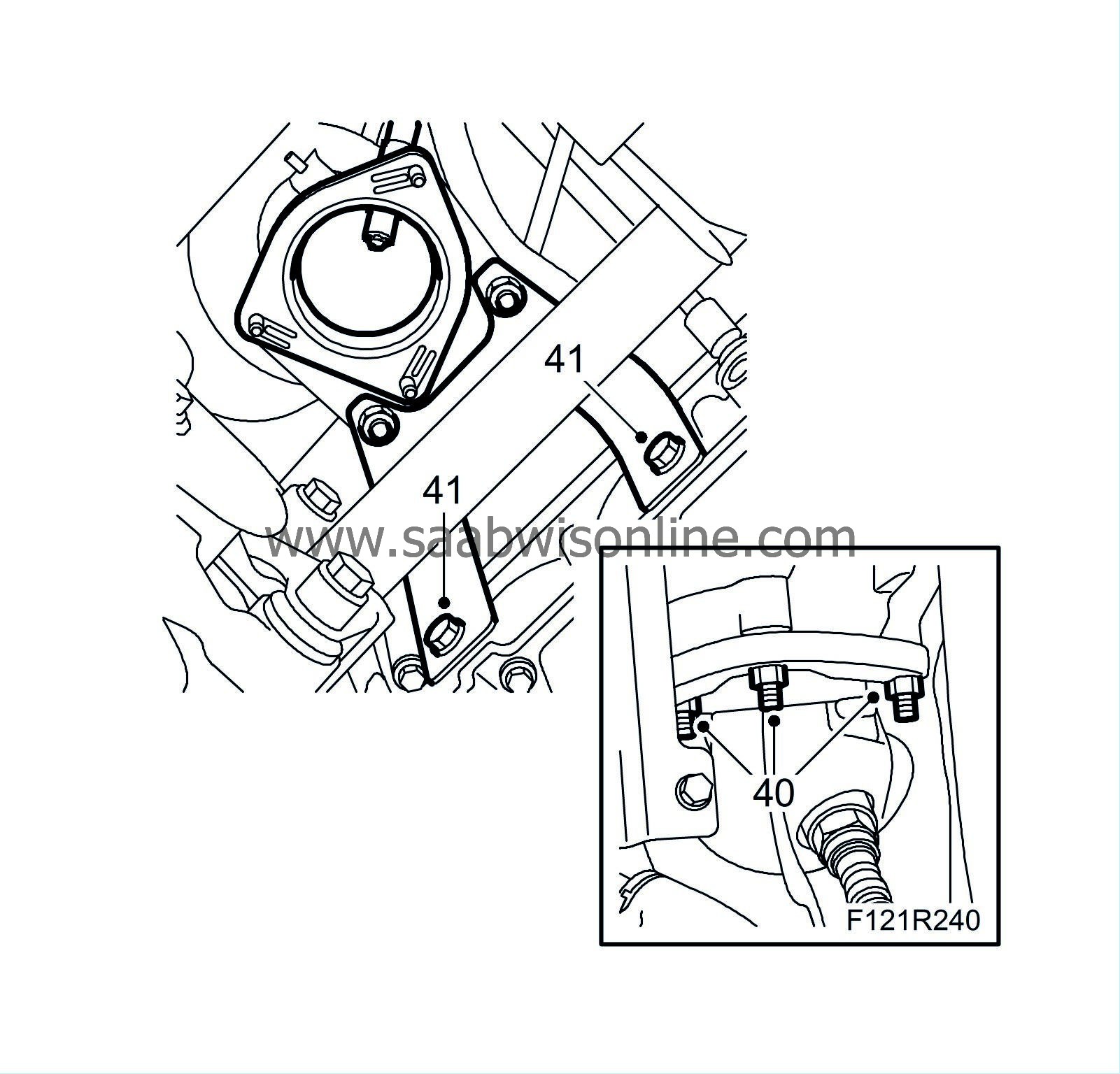
|
|
| 41. |
Raise the car and tighten the catalytic converter bracket bolts.
Tightening torque 25 Nm (18 lbf ft) |
|
| 42. |
Fit the lower turbocharger delivery pipe.

|
|
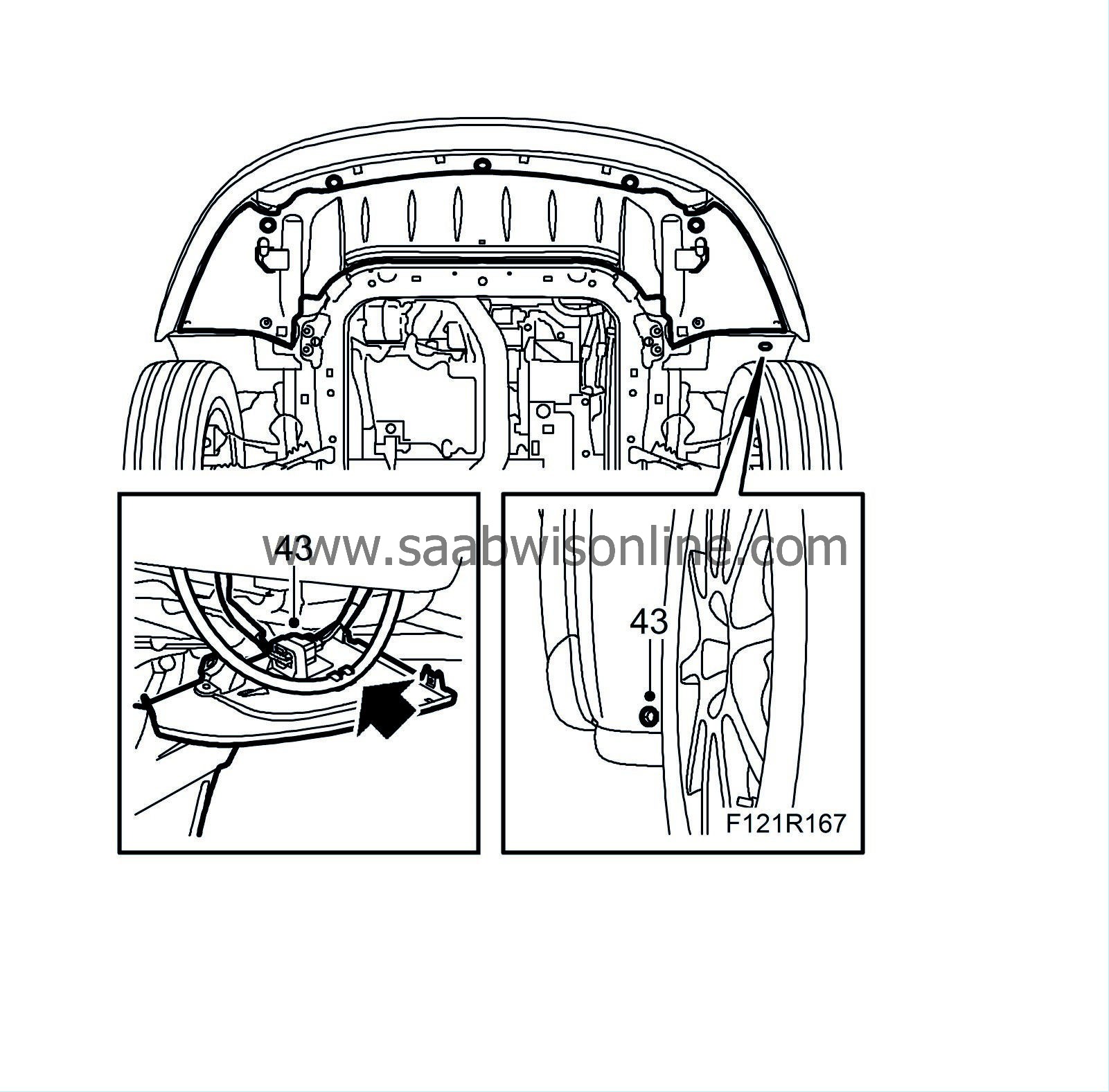
| 43. |
Fit the lower spoiler shield.
CV:
Fit the front subframe chassis reinforcement.
|
|
| 44. |
Lower the car somewhat and fit the right wing liner and the front right wheel. See
Wheels.

|
|
| 45. |
Fit the turbo oil delivery pipe. Use new seals and grip the pipe to prevent it twisting.
Tightening torque 22 Nm (16 lbf ft) 
|
|
| 46. |
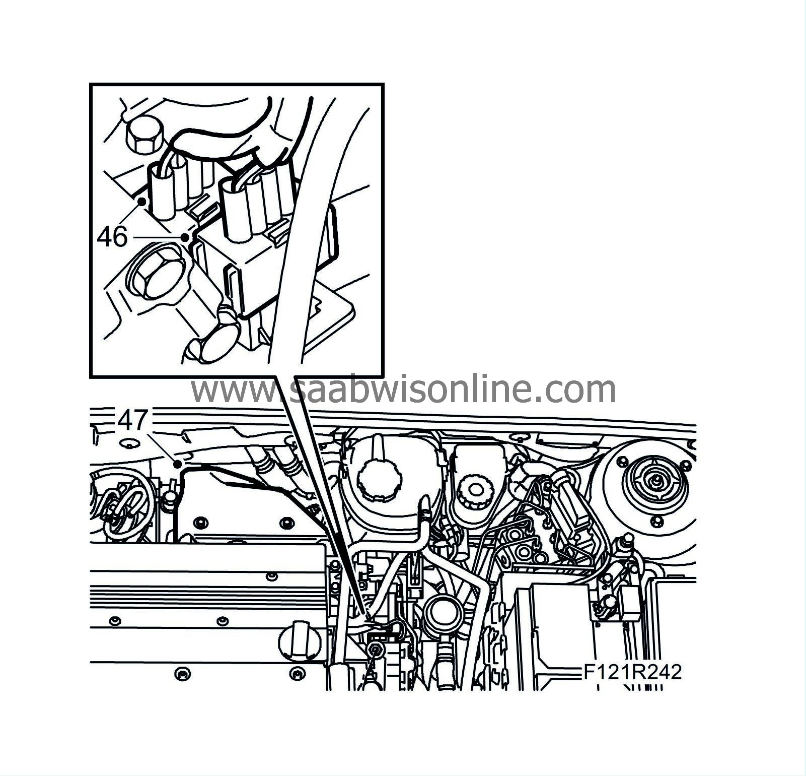
Plug in the oxygen sensor connectors.
|
|
| 47. |
Fit the heat shield over the turbocharger.
|
|
| 48. |
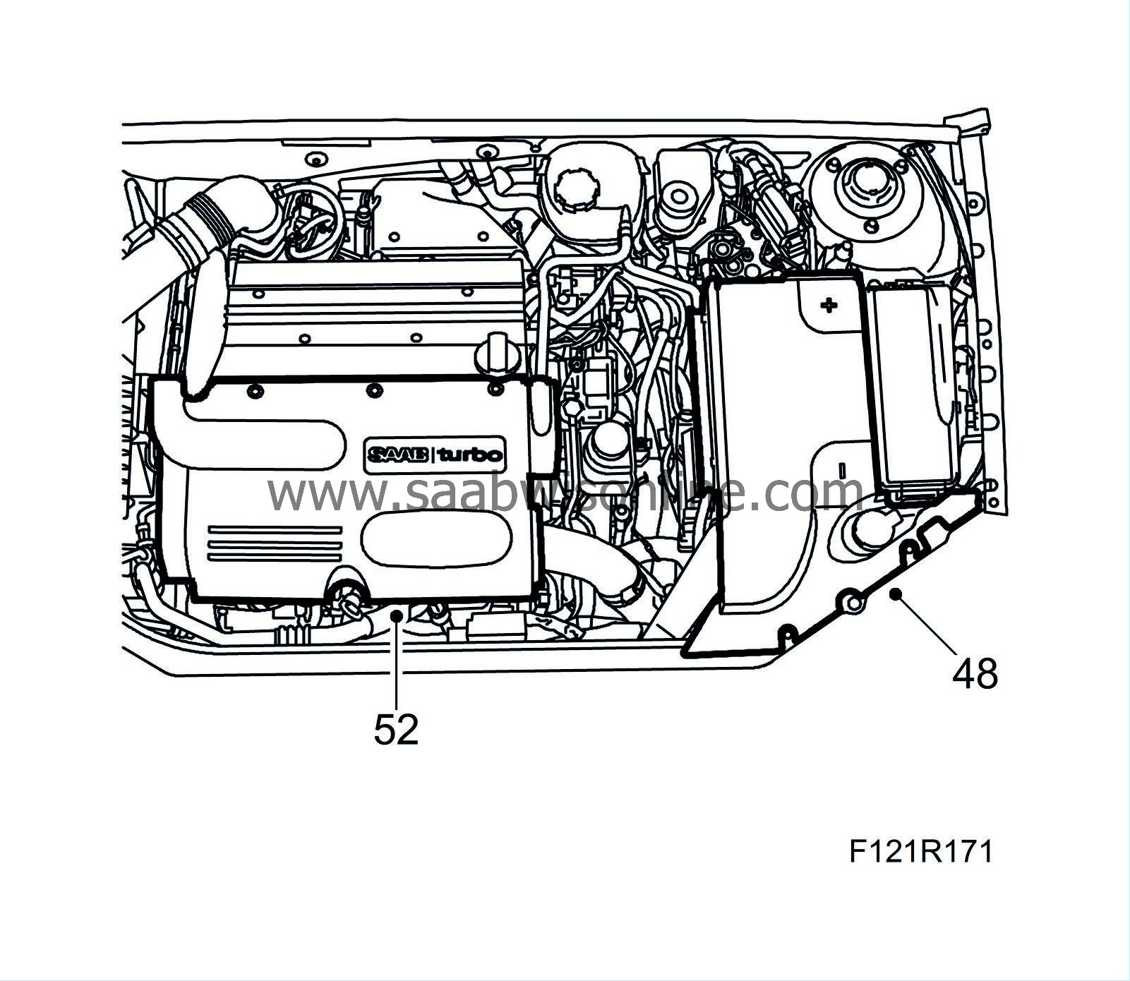
Connect battery negative cable and battery cover.
|
|
| 49. |
Check the oil level and top up as necessary.
|
|
| 50. |
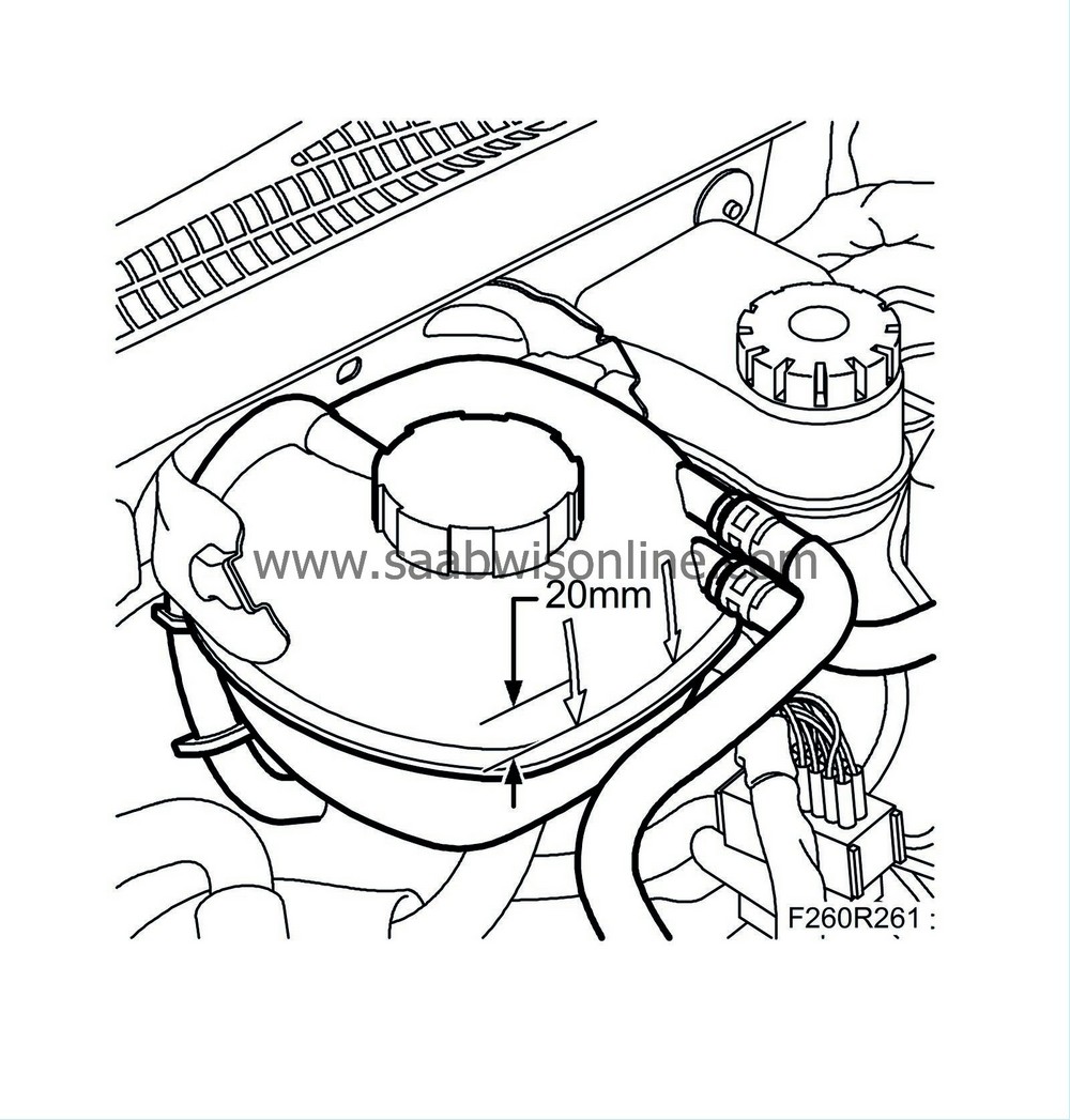
Fill with coolant to approx. 20 mm above the mark on the expansion tank.
|
|
| 51. |
Remove the wing covers and restore car electrical functions, see
After disconnecting the battery
.
|
|
| 52. |
Fit the upper engine cover.
|
|

 Warning


