Control modules, general description
| Control modules, general description |
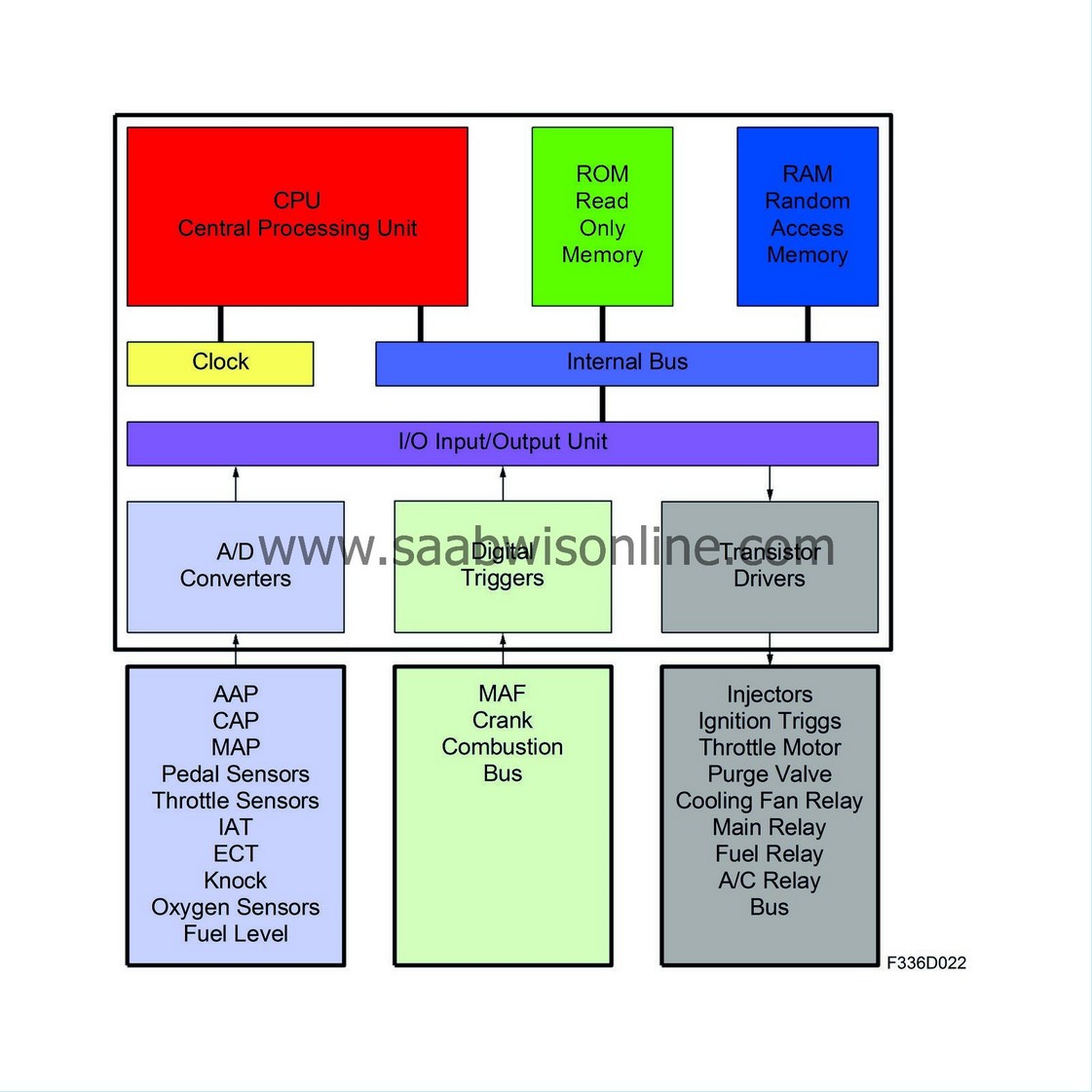
The task of a control module is to control some type of function, such as fuel quantity, ignition time point or interior lighting. The control module governs its outputs based on its program and the values from the sensor and bus.

| CPU (Central Processing Unit) |
The control module microprocessor (CPU) is the unit in the control module that does the work. The CPU performs a calculation each time the internal clock ticks. Which calculation is to be done is determined by the program stored in ROM (Read Only Memory).
A CPU with 8, 16 or 32 bits is used in cars. In a 16-bit computer, 2 bytes are handled simultaneously with each clock pulse.
The CPU of a control module in the car is normally activated when the ignition is switched ON. The control module can also be activated through actuation of a button on a panel, a door being opened or the remote receiver getting a radio signal. Control modules connected to the I-bus can be activated by a voltage pulse. This pulse is close to B+ and is sent by the control module that is doing the "waking", after which it sends its message.
The CPU may sometimes freeze up because it receives unreasonable instructions. This could be an interruption or a combination of input data that was not foreseen when the program was developed. An example of unreasonable instructions is that the control module receives input data that it is to both lock and unlock the central locking system at the same time. The cause could be a cable that got caught in a door.
A frozen CPU is indicated by lack of communication between the control module and the diagnostic tool (despite all conditions being fulfilled), that the CPU continues performing the last instructions, pulling the fuel pump relay, holding a sensor at 2200 rpm or continually activates a lamp.
The easiest way to reactivate the CPU is to briefly disconnect the battery cable or interrupt the power supply to the control module some other way. It is not enough to switch off the ignition if the control module has +30 feed as it is the CPU that determines shut-off.
| Internal Clock |
The internal clock governs when the CPU shall perform a new calculation. The clock has a quartz crystal like those found in wristwatches.
Clock frequencies in a car are much lower than those in a home computer; often approx. 15 MHz.
| ROM (Read Only Memory) |
ROM stores the program memory, i.e. what the CPU is to do, such as switch on interior lighting when the door is opened. ROM is not volatile and is not affected by loss of power. It can sometimes be SPS programmed. In a home computer, ROM is stored on the hard drive, which can hold several GB. In a vehicle control module (vehicle computer), ROM is often only a few hundred KB.
If battery voltage becomes too low during reprogramming, only part of the program will be downloaded to ROM. If this occurs, there is a risk that the control module will lock up and not respond to new instructions from the diagnostic tool.
The diagnostic tool can be used to read system information from the control module. New program versions may have modified or improved properties. Stay informed on which new programs have come out on TIS to avoid unnecessary tracing of a fault that is software-related.
In addition to being stored in the program memory, certain other data is also stored in ROM. In a control module, for example, you can go in under the Adjustments menu of the diagnostic tool and make a change so that the doors lock when you driver faster than a certain speed. This is stored in ROM, not RAM, so that the function does not disappear if the customer replaces the car battery. All values in the diagnostic tool Adjustments menu are stored in ROM for this reason.
| RAM (Random Access Memory) |
Random Access Memory is the working memory. All sensor values and values that the CPU has calculated and will use during travel are stored here. The memory is volatile and is thus erased if there is a loss of power. RAM is like a notebook for the CPU.
The values read using the Read Values menu of the diagnostic tool are from RAM. The CPU retrieves these values from I/O and updates them (overwrites the old value) at specific time intervals. For the tank sensor, the update is once/second, for the coolant temperature sensor 10 times/second and for the mass air flow sensor 1000 times/second. For a crankshaft position sensor, update is done with the highest priority as soon as the value changes.
Thus, RAM always has the latest sensor data. Not only does the control module update sensor values at specific time intervals, it must also perform a task, such as inject fuel or lock a door. The program for the different functions retrieves the necessary sensor values from RAM and makes its calculation. The result of the calculation is the output value delivered to I/O, which then activates the relevant output. RAM in a home computer currently averages between 64 and 256 MB. In a car computer, the size is about 2 KB.
| Internal Bus |
The internal bus is leads in the control module that the CPU uses to retrieve data from ROM, as well as transmit data to and retrieve data from RAM and the Input/Output unit.
| I/O Unit |
The Input/Output unit receives values from sensors and delivers outputs to transistors in the power amplifiers. Data is transferred internally to and from the CPU.
In your home computer, most I/O is handled by the mother board, which takes care of the mouse, keyboard, monitor, printer and communication ports. Extra I/Os can be fitted, e.g. modem, network or sound.
| A/D Converters |
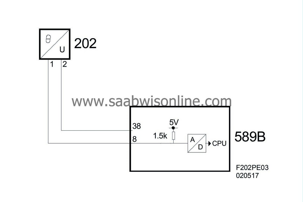
Analogue/Digital Converters convert analogue sensor values to digital values that the CPU can read (via the Input/Output unit). Converts in 256 steps as this corresponds to one byte or 8 bits.
8 leads go between the A/D converter for a temperature sensor, for example, and the Input/Output unit. If all are 0 (no voltage), it means that voltage over the NTC resistor is 0 V. See below for more information on A/D conversion.
| NTC voltage (V) | Digital (binary) | Decimal |
| 0 | 00000000 | 0 |
| 0.02 | 00000001 | 1 |
| 0.04 | 00000010 | 2 |
| 0.06 | 00000011 | 3 |
| 0.08 | 00000100 | 4 |
| 0.1 | 00000101 | 5 |
| 0.12 | 00000110 | 6 |
| 0.14 | 00000111 | 7 |
| 0.16 | 00001000 | 8 |
| ... | ... | ... |
| 5.00 | 11111111 | 255 |
Some control modules have analogue inputs with 10-bit conversion. The advantage is improved accuracy or resolution. Resolution doubles with each extra bit.
10 bits means 1024 steps for an analogue sensor. This is used for pedal position sensors, for example. In most cases, however, 8-bit conversion is sufficient. 256 steps is sufficient for a tank sensor, for example.
Pull-Up and Pull-Down
The A/D converter is connected to a sensor via a control module pin. The pin has a pull-up or a pull-down. A pull-down is a resistor that has a high number of ohms and pulls to ground (connected in the control module between the pin and ground on the circuit board). A pull-up works the same way, but pulls the pin to a specific voltage (often 5 V or B+).A pull-up must be used on passive sensors, such as NTC, so that one can have a voltage to read. Otherwise, a pull-up or pull-down is primarily used for diagnostics to draw the pin voltage to an unacceptable value in the event of a break on the lead.
If an analogue control module input has a pull-up, you can be sure that diagnostics cannot distinguish between a break and a short-circuit to B+. In the same manner, diagnostics cannot distinguish between a break and a short-circuit to ground if there is a pull-down.
In fault tracing, one is often instructed to connect a jumper to an analogue control module input with pull-up to ground. The diagnostic tool then changes the value from, for example, -40*C to 150*C. This shows that the lead is whole.

| Digital Triggers |
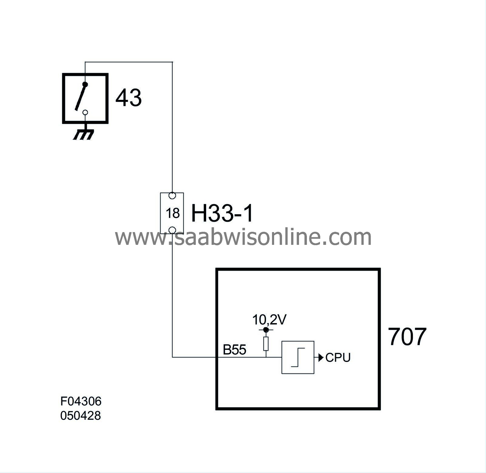
Digital Triggers handle inputs that are already digital but need conversion from voltage levels to 1 or 0 before being processed by the Input/Output unit.
Here, a pull-up or pull-down must be used so the input goes to a specific position when voltage or ground is not applied to the pin. There is no point in grounding a pin to indicate if the door has been opened if the pin is already at 0 V.
In fault tracing, one is often instructed to connect a jumper to a digital control module input with pull-up to ground. The diagnostic tool then changes the value between, for example, Off and On. This shows that the lead is whole.

| Transistor Drivers |
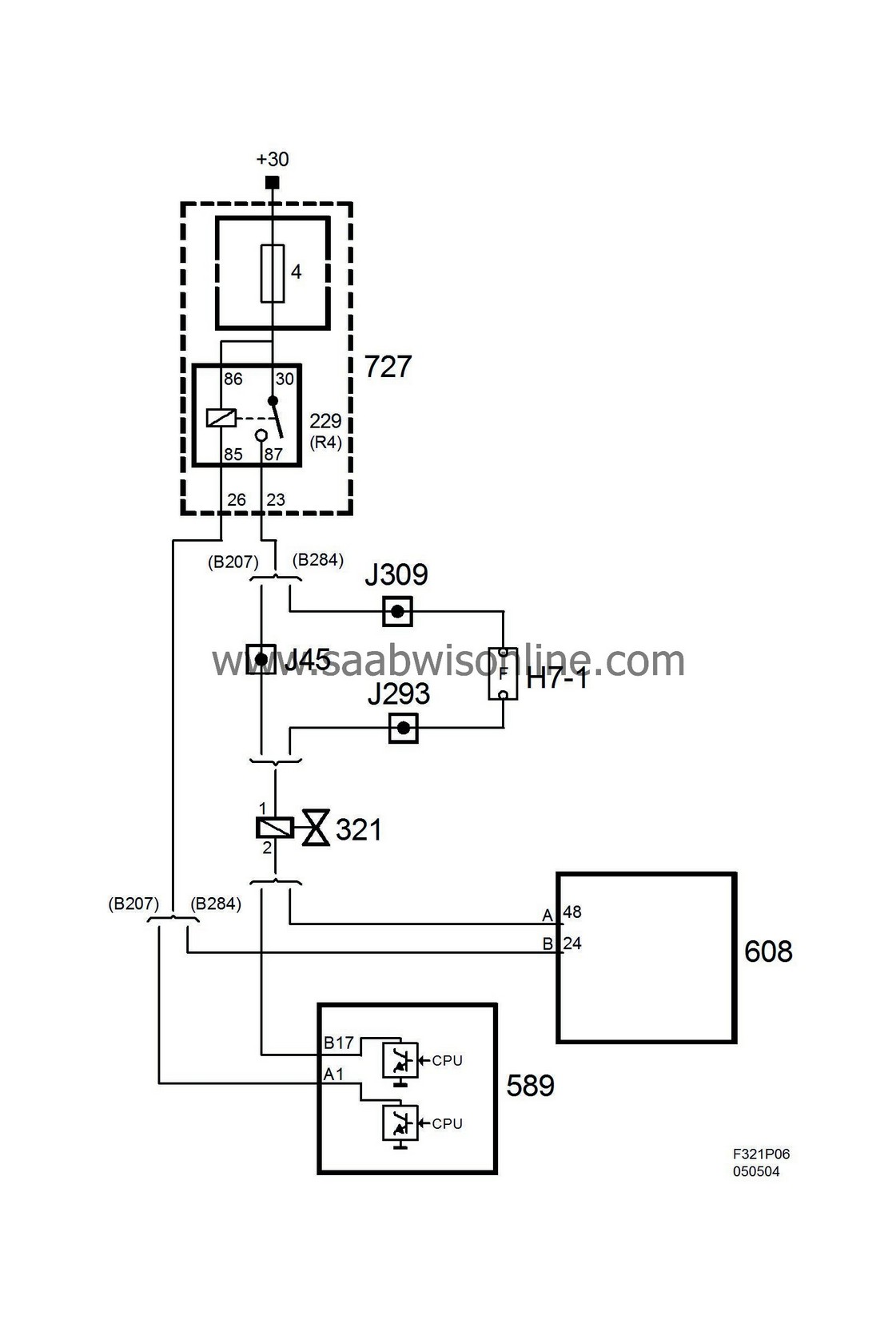
Transistor Drivers activate the components that perform the task for the CPU by, for example, grounding a relay coil or an interior lighting bulb.
The power amplifier transistors are power grounded, often through an extra thick pin in the connector. The lead, often 1-2.5 mm2 then goes to the body and is grounded separately from the signal ground, which feeds other internal components of the control module.
If there are great loads, such as from the radiator fan, ventilation fan, fuel pump or glow plug, additional power amplifiers or relays may be used.

The illustration above includes a pull-down. It has a high number of ohms and cannot ground the lead when the component is connected. The purpose of the resistor is simply to keep the pin pulled to ground in the event of a break so that diagnostics can find the fault.
A transistor driver can also be connected in the control module in such a way that it puts out B+. This has been used previously for direction indicators (ICE/DICE) and is now used for exterior lighting in UEC and REC.
In fault tracing, one is often instructed to test an output with an LED. For normal outputs that ground, it is connected between B+ and the control module output. When you then activate it with the diagnostic tool, the LED should light. This shows that the lead is whole.


