Detailed description
| Detailed description |
All vehicle control modules are connected to buses, where messages are transmitted electronically.
The buses are divided into P-bus (Powertrain Bus) and I-bus (Instrument Bus). The P-bus has two leads while the I-bus has one. The voltage difference between the leads (P-bus) takes only two values, approx. 0 and 2 V. Between the lead and ground (I-bus), the voltages are approximately 0 and 5 V. The information is coded so that different combinations of pulses mean different things.
| P-bus and I-bus |
Both electric buses are connected to the column integration module (CIM) and the data link connector. The buses are electrically isolated.
The I bus is split into two separate loops where the difference is the number of bits in the length of the message. These loops are also electrically isolated. The body control unit (BCM) is a gateway, which means that it conveys information between the loops.
CIM is a gateway between the P and I buses, i.e. it conveys information between them.
The data transfer rate of the P bus is 500 kbps while the I bus is 33 kbps. The reason for the difference in transfer rate is that the powertrain system requires information with the least possible delay, for example for air mass compensation when the gear selector is moved from N to D or for TC or ESP engagement. Vehicles with 2.0 SIDI engine use an ECM and a TCM with other identifiers for their bus messages. This requires a converter. The Signal Conversion Module (SCM) on these vehicles is connected to the P bus. It reads, converts and retransmits the bus messages.
The control modules send out information on the bus whenever the information changes. As a safety precaution, the information is also sent at regular intervals irrespective of whether or not it is new. The time between two transmissions depends on the information being transmitted and varies between 10 milliseconds (engine torque) and 10 second (VIN). When a control module sends information, the other control modules listen regardless of whether or not they use the information.
A bus system means that it is sufficient with one sensor for each measurement function in the car. The number of separate signal leads can also be reduced. For example, the engine management system has a coolant temperature sensor, which means that coolant temperature is always available to all systems. Therefore, the car only needs one coolant temperature sensor. Coolant temperature is used by the main instrument unit to control the temperature gauge, and the ACC to control ventilation fan speed and air distribution when starting from cold.
I-bus, principles of communication
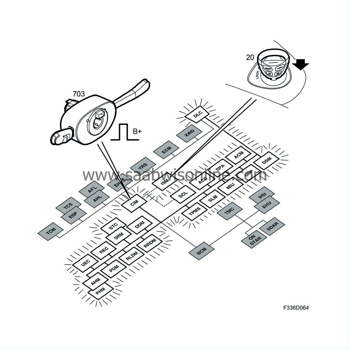
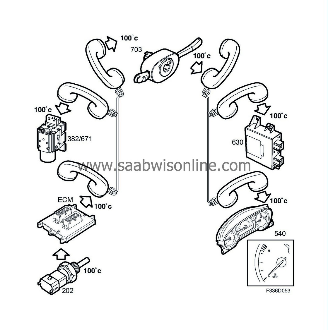
You can think of the bus as a telephone line running between the control modules. The I-bus system does not have a +15 power supply lead, with the exception of for the airbag control module (ACM). With the ignition switched on, communication goes on continuously. The CIM determines the key position from information from the ignition switch module (ISM).
When the key is inserted into the ignition, the CIM wakes the other control modules on the I-bus by briefly sending B+ over the bus. The CIM then sends regular reports over the bus of the key position.
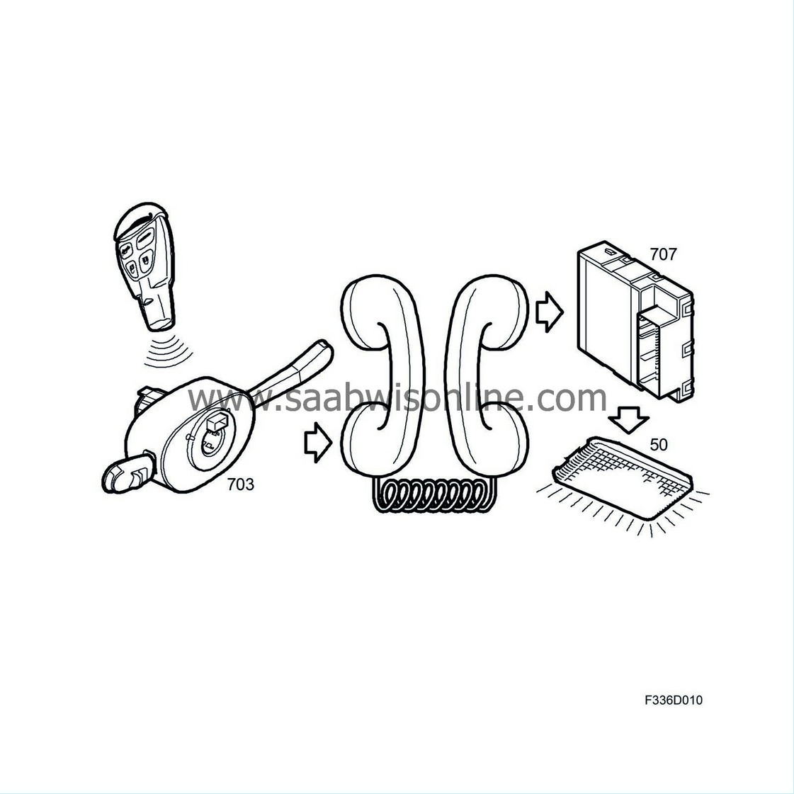
Communication can still be started even if the key has been removed from the ignition switch. For example, if you press the open button on the remote control, the CIM, which receives the signal, wakes the other control modules so that the body control module (BCM) can turn on the interior lighting and the driver door module (DDM), for example, can unlock the door. The control modules go back to sleep when no messages concerning them are sent on the bus.
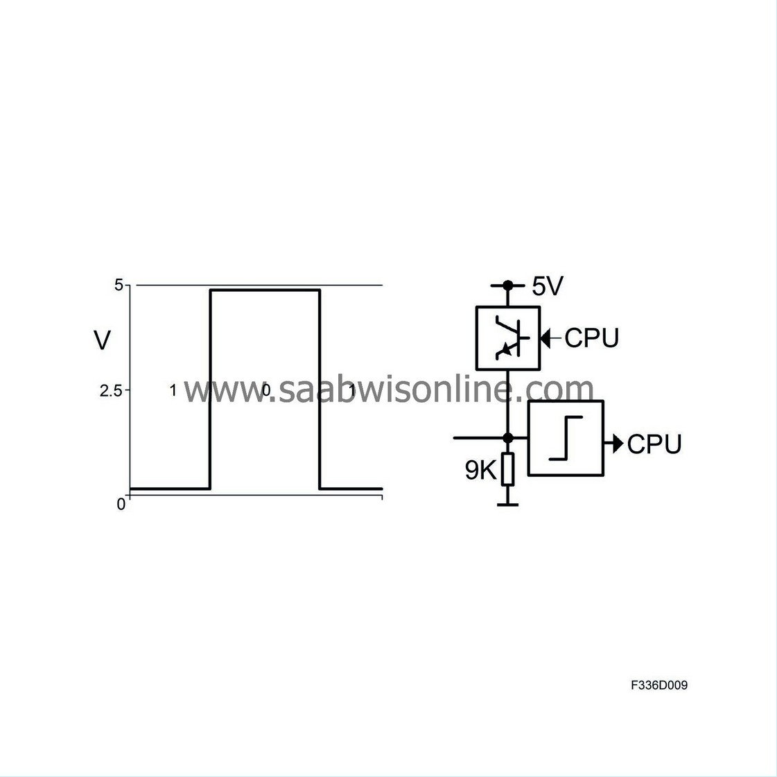
The bus lead is a green cable that is internally grounded in each control module via a 9 kΩ or a 4 kΩ resistor. MIU, BCM, DDM, PDM, CIM, RRDM, RLDM and REC are the control modules grounded internally via a 4 kΩ resistor. To send a zero, the control module raises the bus lead voltage towards 5 V. A potential difference to ground lower than 2.2 V is interpreted as a one, and higher than 2.2 V as a zero. Note that a long series of ones is the same as no message being sent.
P-bus, principles of communication
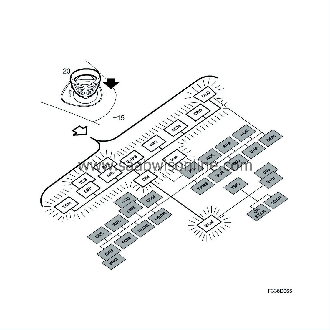
The P-bus system has a +15 lead coming directly from the ISM. With the ignition switched on, communication goes on continuously. Communication stops as soon as the ignition is switched off. The P-bus does not have a wake-up function similar to that of the I-bus.
The two bus leads (a blue wire for bus + and a white wire for bus -) are fed with roughly 2.5V by each control module. The voltage is created using three resistors connected in series between 5V and ground. The middle resistor means that the voltage on bus + is slightly higher than that on bus - when no message is being sent.
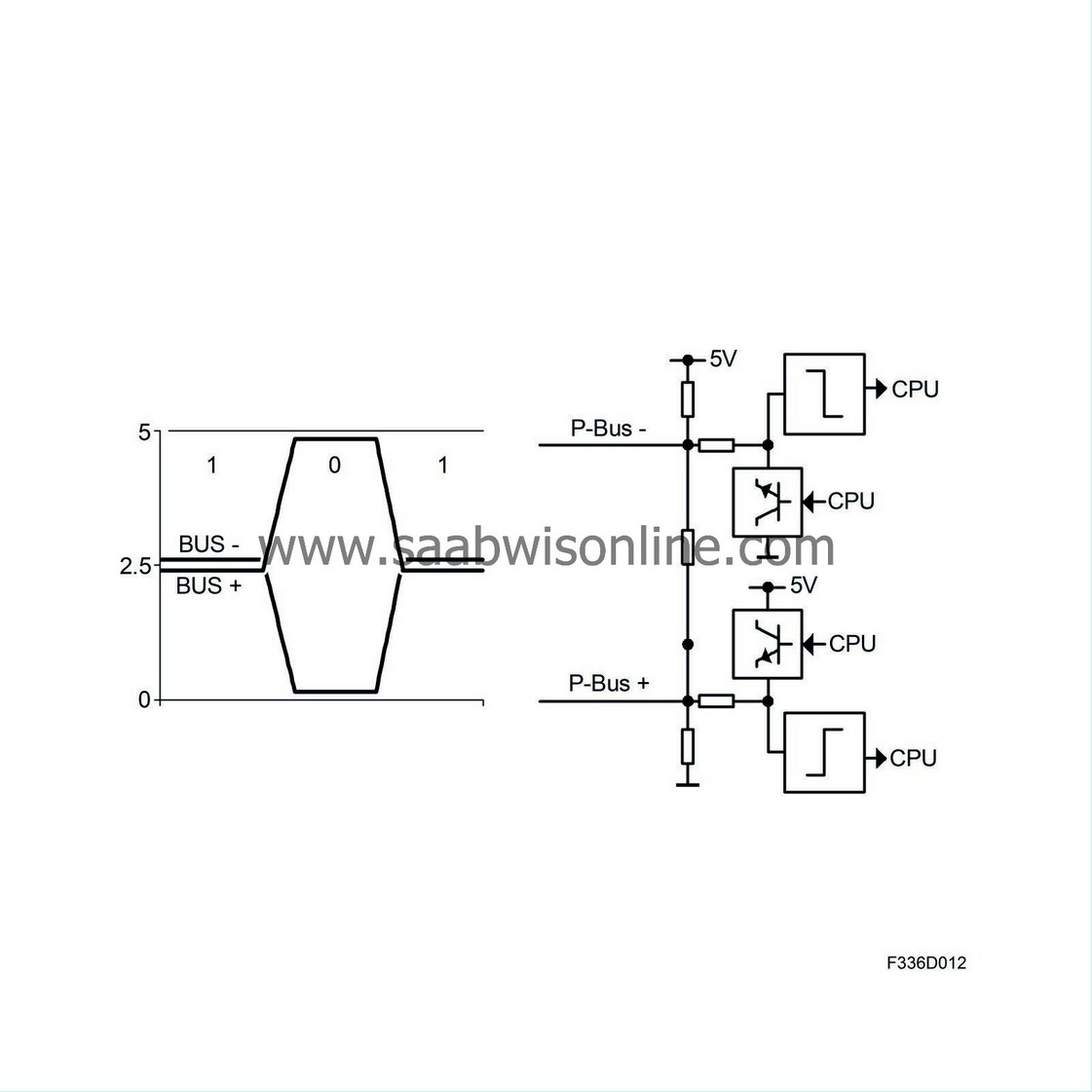
A one is sent when the voltage on both leads is roughly 2.5 V for a certain period of time (2 millionths of a second). A zero is sent when the control module raise the voltage on bus + towards 5 V and lowers that of bus - to ground for the same period of time. A potential difference lower than 1.5 V is interpreted as a one, and higher than 1.5 V as a zero. Note that a long series of zeros is the same as no message being sent.
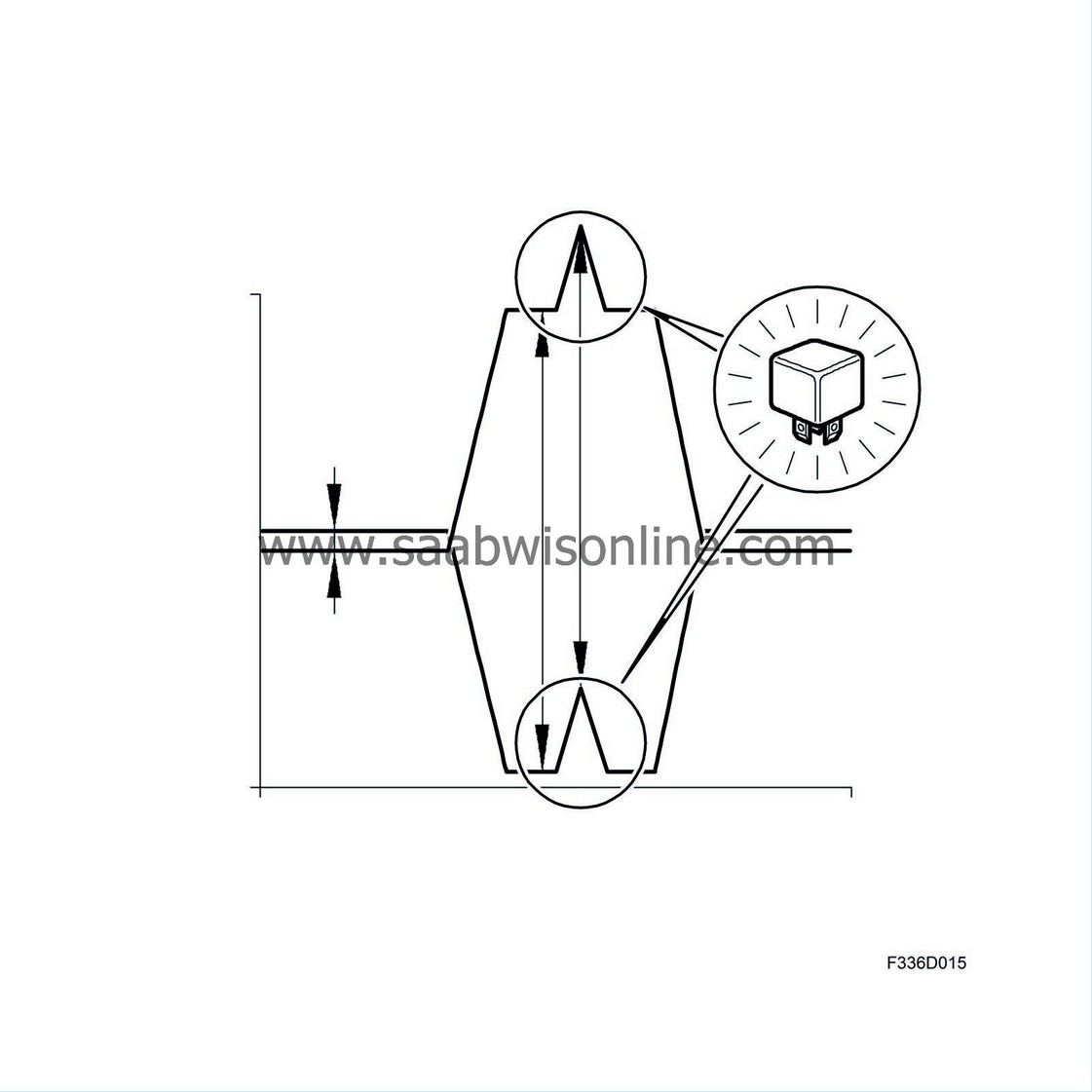
The P-bus, which has a high data rate, has two wires to reduce its sensitivity to interference. A possible source of interference, such as a relay, will have the same affect on the voltage of both wires. The difference in voltage between the wires will therefore remain the same, and the message will not be affected. The wires are also twisted to further reduce their sensitivity.
P-bus and I-bus, message transmission and reception
A control module sends a message by sending ones and zeros in a predefined order. The control module only sends a message if no other control module is presently sending. When one control module sends a message, all the other control modules listen, interpreting the combination of ones and zeros. The meaning of the combinations of ones and zeros is predefined so that all the control modules can interpret the information in the same way. The message contains information about what is being sent and the value, for example "Coolant temperature 100°C" or "A/C ON".
| Diagnostics communication |
The P and I-bus are routed to the data link connector. Tech2 with adapter is connected to the data link connector and communicates directly with the various control modules on the P and I-bus.
In a bus system, all units must be able to communicate with each other. For example, the engine cannot start if ECM cannot receive the immobiliser information transmitted by CIM. Bus faults can be caused by disconnection of a bus lead, which causes one or more systems to disappear from the bus in question depending where the open circuit occurred in the wiring harness. If a bus lead is short circuited, all systems disappear from the bus in questions (P or I-bus). In the event of a ground or power supply fault to one or more systems, they will stop communicating.
In theory, control modules connected to the bus can be considered as one large control module with a number of sensors and actuators. Bus communication is comparable to internal control module communication. This means that it is vital to consider the entire vehicle when diagnosing faults. A fault may not necessarily lie in the system in which it becomes apparent but may be caused by a faulty sensor in another system.
Permanent bus faults
The MIU contains lists of all control modules on the buses of the vehicle in question. When diagnostic trouble codes are read, Tech2 will always start by contacting MIU to read out which control modules should be found in the vehicle. There is then a check to see which control modules are communicating in the vehicle. If a control module is missing or there is an extra control module, this will become apparent. Nothing will appear if the quantity and identity are correct. If there is a difference, it will be possible to begin fault tracing or accept the new control module configuration. An example of this would be after mounting an extra control module or permanently removing one. Tech2 will then change the lists in MIU so that there will be no warning in the future. If a bus-connected control module is missing, Tech2 will indicate such. Thus, if the diagnostic tool does not generate a warning, all bus-connected control modules are communicating.
Intermittent bus faults
The ECM and TCM continuously check that all the control modules from which they receive information are communicating correctly. In the event of an intermittent fault in bus communication with one of these systems, DTCs will be generated in the ECM and TCM. The reason for the fault may be the bus leads or that the control module in question lacks power.
Fault counter
To facilitate fault diagnosis, the control modules on the I and P-bus have fault counters. A counter counts up each time bus communication with the control module is broken and the module loses contact with all other control modules. If the counter value of only one control module increases, the problem is local and easy to find. If the values of several control modules increase, wiring diagrams must be used to see how the control modules are interconnected. A total short circuit will cause all the control modules on the bus in question to count up. The counters stops at 255 and can be reset with Tech2. A counter showing 255 must be reset to be of any use. Intermittent faults can be detected by jiggling the wiring harness. Problems with the power supply or grounding will not be counted by the counter, despite a loss of communication, since the control module itself is then out of order.
| Note | ||
|
It is not uncommon and perfectly normal for the value of a counter in a car that has been driven large distances to be 255. |
| Description of LIN bus |
The Local Interconnect Network (LIN) is used as a serial bus for communication and network between intelligent sensors and actuators that work together with the battery voltage. The maximum communication rate on an LIN bus is 19,200 bps. The voltage is held at B+ with a 1K pull-up resistor and the units signal with ground pulses.
The control module connected to the P or I bus is called the "Master" and the remaining LIN units on the same bus are called "Slave". The Master is used to coordinate the information from the slaves and to set DTCs if anything is missing. Fault diagnosis is the same as for the I bus. The Saab test lamp flashes when communication is in progress. In case of a DTC for a missing slave, measure bus (LIN), + and -.
| C-cable |
A C-cable is a communications lead, which in actual fact is a single-wire bus for slow communication between two modules. Such a lead has a maximum transfer rate of 10 kbit/s. Communication is serial and bi-directional. The diagnostic tool is connected to the bus, as are all control modules. All the same, there are a number of C-cables.
Most often, one or both of the modules use a pull-up resistor to raise the voltage on the lead to close on B+. Transmission and reception then take place in accordance with a predetermined protocol. Component manufacturers use the protocol as a standard for message structure to avoid misunderstandings.
Examples of C-cables
The BCM communicates with the alarm siren module (ASM) and alarm sensor via a C-cable.
The CIM communicates with the ignition switch module (ISM) and steering column lock (SCL) via C-cables.
The ACM and front and side sensors communicate over C-cables.
Diagnosis of C-cables
The control module that is connected to the bus expects data on the C-cable under certain conditions. If the control module does not receive any data it generates a DTC. The fault may not necessary lie in the lead, it may be that the sending module is not energised or grounded.
| Function chains |
A large number of function chains can be identified in the bus system. Described below are four examples of important chains.
1. Vehicle speed
The TCS/ABS or ESP control module measures vehicle speed with the help of a Hall sensor at each wheel. The sensor supplies the control module with alternating current, the amplitude and frequency of which increase proportionally with increasing wheel speed. The ECM calculates the average speed of the two non-driven wheels, correcting this value for the type of tyre programmed. The ECM then sends this value for vehicle speed over the bus making it available to other systems.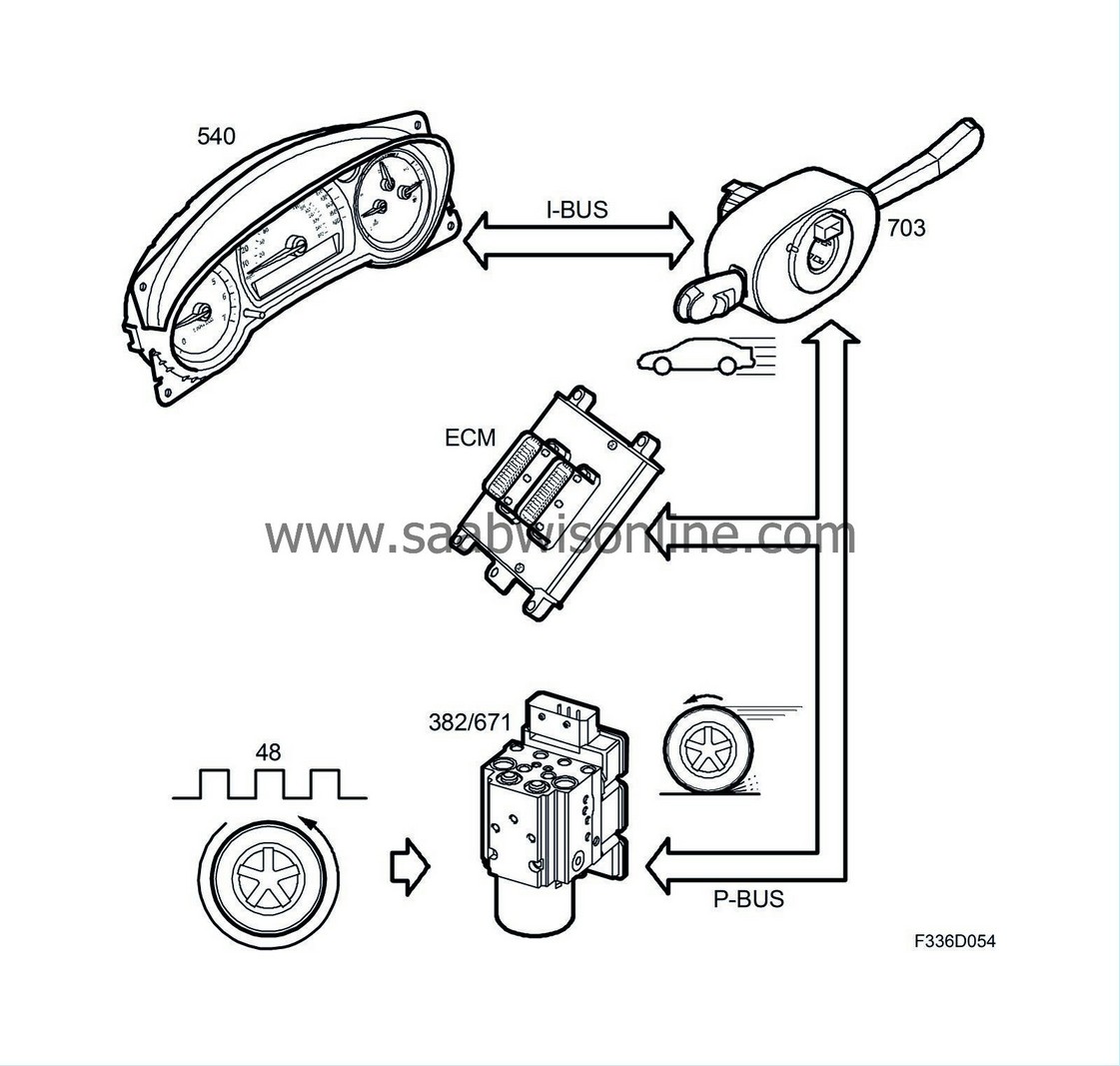
In the table of bus messages, you can see that the ECM sends the value for vehicle speed and that the majority of other control modules use this.
Examples:
| - |
The ECM itself uses vehicle speed for cruise control, idle speed control and a number of diagnostic functions. Pulling off (certain markets only).
|
|
| - |
The MIU uses the value for the speedometer.
|
|
| - |
The CIM uses the value for the steering column lock.
|
|
| - |
The ACC uses the value for activating recirculation at high temperatures and low speeds, to reduce the fan speed at high speeds, and to calculate the cabin temperature.
|
|
| - |
The audio system uses the value for increasing the volume at high speeds.
|
|
| - |
The BCM uses the value to automatically lock the doors after pulling off (certain markets only).
|
|
2. Immobilisation
When the ignition is switched on, the MIU checks that the correct key is inserted in the ignition switch. A circuit built into the remote control part of the key sends a code to a coil in the ISM by means of inductance. The code is passed on via a K-lead to the MIU, which checks that it is correct. The MIU also checks that the right BCM and PDM are fitted in the car. These are all part of the car's "immobiliser environment" and continuously send an ID number over the bus. If the key and control module ID numbers are OK, the MIU will send a message for "Immobiliser OFF" on the bus. The ECM acts on this information by cancelling fuel shut-off, which is always activated whenever the ignition is turned on.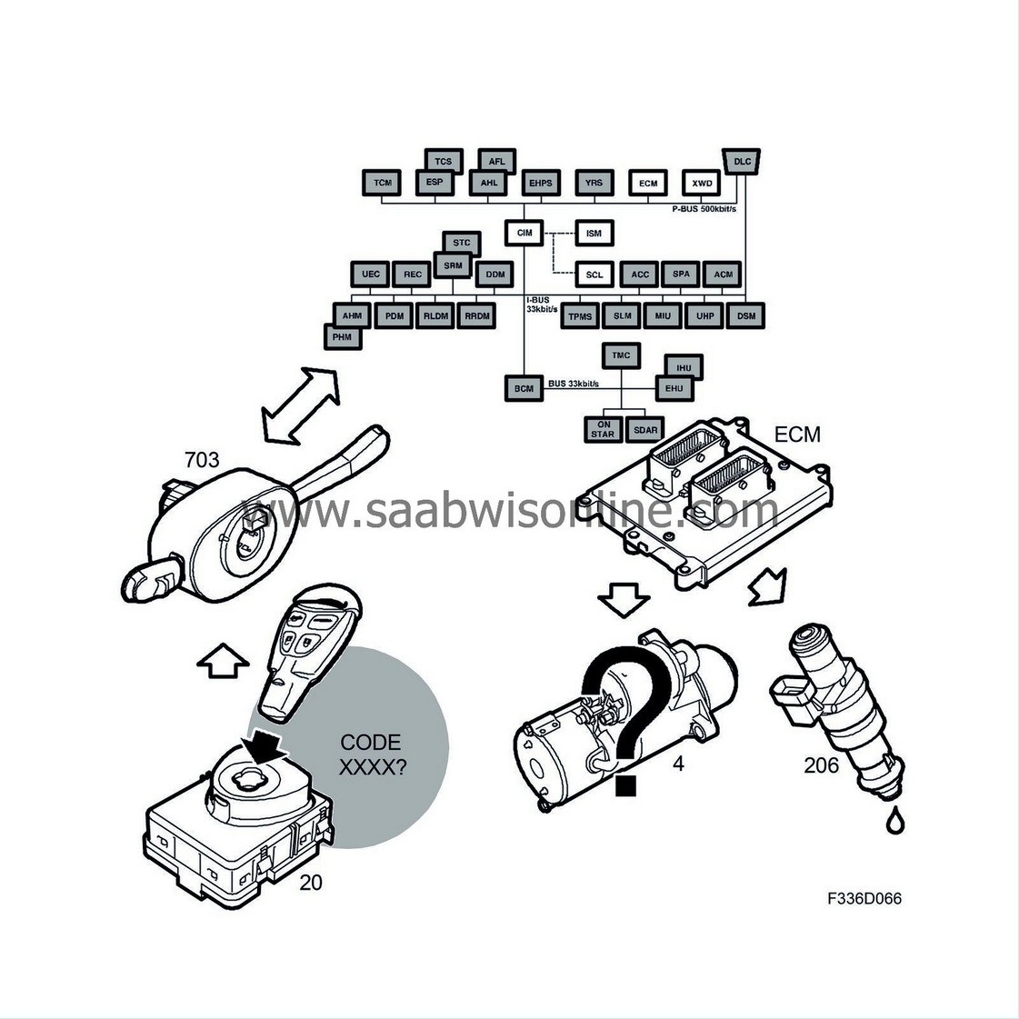
3. Steering column lock
Turning the ignition OFF locks the steering column. The MIU first checks that vehicle speed does not exceed 5 km/h. The problem here is that the TCS/ABS or ESP and ECM provide the value for vehicle speed. These control modules are connected to the P-bus and there is no communication on the P-bus when the ignition is switched OFF. To solve this problem, there is a direct lead from the TCS/ABS or ESP providing a wheel speed signal. The TCS/ABS or ESP can read the wheel sensor values and transmit a speed signal since it has a separate +X feed (battery voltage with ignition switch ON or OFF).
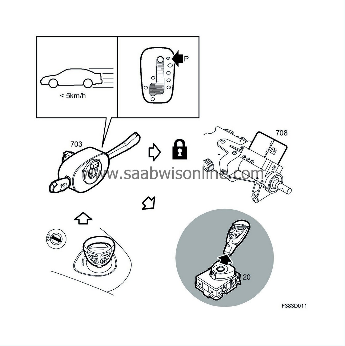
As well as checking that vehicle speed does not exceed 5 km/h, the MIU checks that the selector lever in cars with automatic transmission is in position P (I-bus from SLM). When these conditions are fulfilled, the MIU sends a signal on a K-lead to the ISM to release the key. The key can now be turned to LOCK and removed. Only now is the steering column locked.
When the key is inserted into the ignition switch, the steering column lock is released if the transponder is approved. If the car is parked in such a way that the steering shaft bears against the lock bolt, it may not be possible to release the lock. The MIU will in this case send a message on the bus that the MIU, via the SID, can instruct the driver to remove the key, turn the steering wheel and reinsert the key.
4. Central locking system
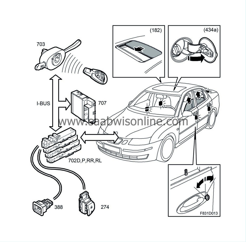
The BCM contains all the logic for the central locking system. When you press the remote control to unlock the car, the MIU receives a radio message. The MIU wakes the other control modules on the I-bus and informs of which button was pressed and how (e.g. single press). The BCM sends an unlock command over the bus, at which the four door modules (DDM, PDM, RRDM and RLDM) unlock their respective doors. The REC unlocks the boot lid and the BCM unlocks the fuel filler flap.
4D
CV
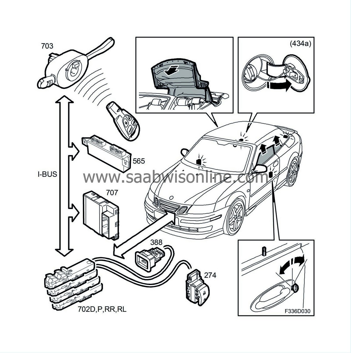
The BCM contains the central locking logic and can be programmed to unlock only the driver's door and fuel filler flap if the unlock button is only pressed once.


