Detailed description
| Detailed description |
The sleeve has three radial grooves (7), the power steering fluid being pumped to the middle one. When the steering wheel is in the straight-ahead position, the control valve is open and the fluid flows up through the valve and back to the power steering pump via the chamber above the sleeve.
The upper end of the pinion is mounted in a needle bearing while the lower end is mounted in a ball bearing. A spring-loaded plunger presses the rack against the pinion.
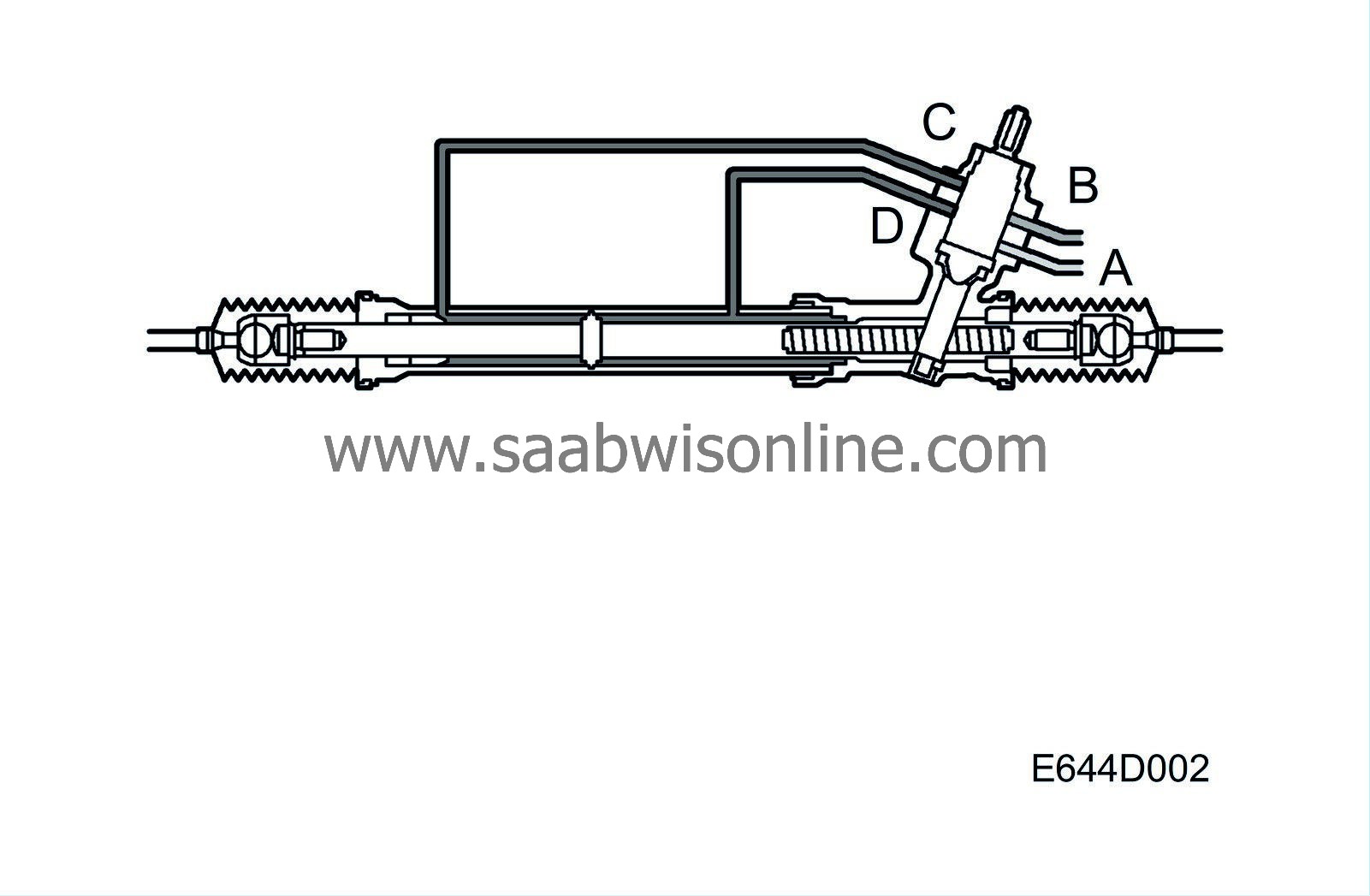
The valve housing, which is part of the steering gear housing, has four connections for the flow of power steering fluid: Servo delivery from the power steering pump (A), return to the power steering fluid reservoir (B), to the servo cylinder when turning right or from the servo cylinder when turning left (C) and to the servo cylinder when turning left or from the servo cylinder when turning right (D).
When the steering wheel is turned, the movement is transferred via the torsion bar to the pinion. Since the torsion bar is somewhat elastic, there will be a difference between the degree of rotation of the valve spool (which follows the rotation of the intermediate shaft) and the sleeve which is fixed to the pinion. As a result, the fluid can no longer flow through the control valve and back to the power steering fluid reservoir directly. Instead, delivery and return passages open for the servo cylinder.
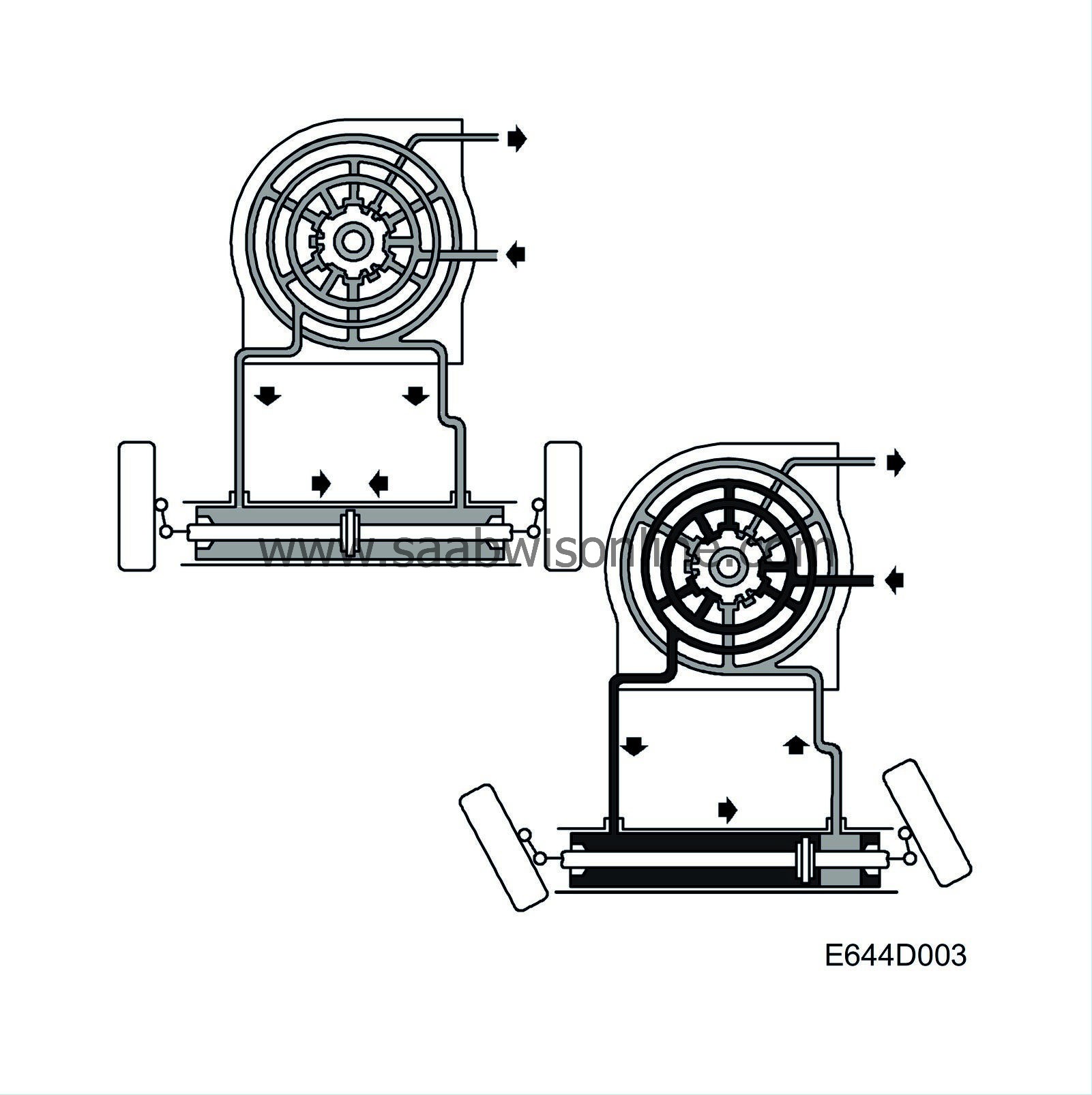
When turning left, power steering fluid is pumped to the left-hand side of the servo cylinder via the upper radial groove of the sleeve. At the same time, the right-hand side of the servo cylinder is emptied via the lower radial groove of the sleeve. Power steering fluid is led up through the valve to the chamber above the spool and on back to the power steering fluid reservoir. When turning right, the process is reversed. As long as the torsion bar is twisted, power steering fluid presses on the rack so that servo effect is obtained. The difference between the valve spool and the sleeve reduces when the power steering fluid actuates the rack in the same direction as the pinion. When there is no longer a difference, the valve opens the passage returning power steering fluid to the reservoir. Some power steering fluid continually circulates in the valve except when the steering wheel is turned to an end position. This makes it possible for the control valve in the power steering pump to work while circulation cools the power steering fluid.
| Servo cylinder |
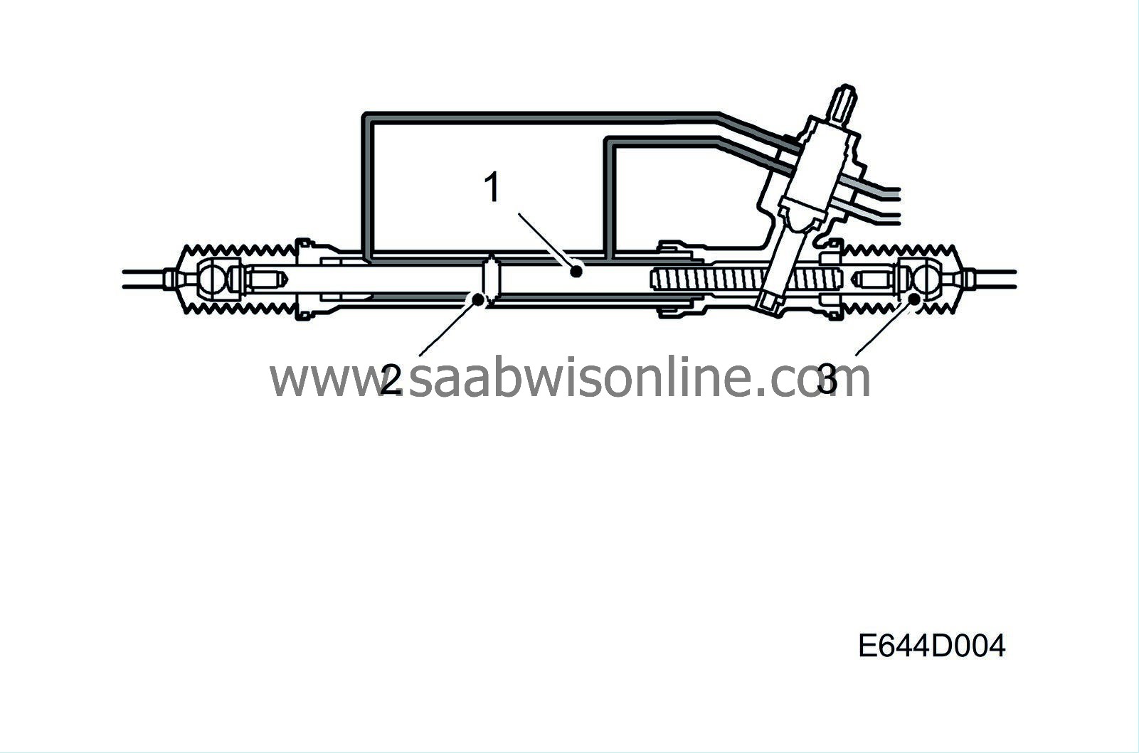
The cylinder is part of the steering gear housing. The rack (1) is equipped with a piston (2) complete with seals. For the flow of power steering fluid to and from the control valve there are two connections on the servo cylinder, one on each side of the piston. When turning right, power steering fluid is pumped to the right-hand section of the servo cylinder.
Piston and rack are forced to the left and power steering fluid is discharged from the left-hand section of the servo cylinder. The rubber gaiter on the left-hand side is distended at the same time as the one on the right-hand side is compressed.
Movement of the rack is transferred via the inner ball joints (3), track rod and outer track rod ends to the steering arms of the steering swivel member. Both the inner ball joints and the outer track rod ends are lubricated for life and self-adjusting, with no further lubrication or adjustment being necessary or possible.
| Pump operation |
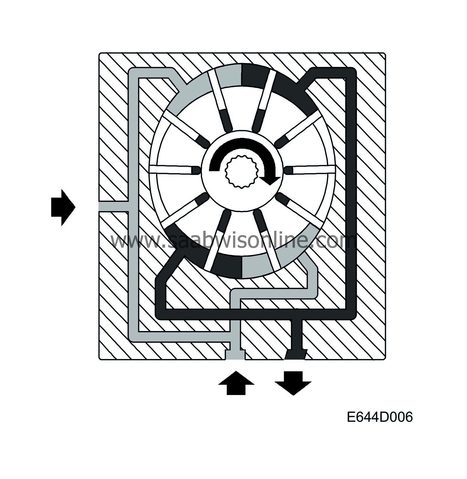
The pump element consists of a rotor with a number of slits, a vane for each slit, a pump ring and two end plates with inlet and outlet ports for power steering fluid. If for some reason the power steering pump of a petrol engine is damaged and thus starts running sluggishly or stops, there is a disconnect function integrated in the drive shaft to the power steering pump which runs at approx. 80 Nm. This protects the cam train.
Due to the oval shape of the pump ring, the volume between the vanes increases and decreases twice during each revolution of the rotor. Inlet ports lead to the areas in which the volume increases and outlet ports lead from those in which the volume decreases, thereby producing a pumping effect. Apart from being forced outwards by centrifugal force, the vanes are also pressed outwards against the pump ring by the pressure of the fluid. The fluid is directed into the slots inside the vanes.
See also Power steering pump .
| Pressure and flow control |
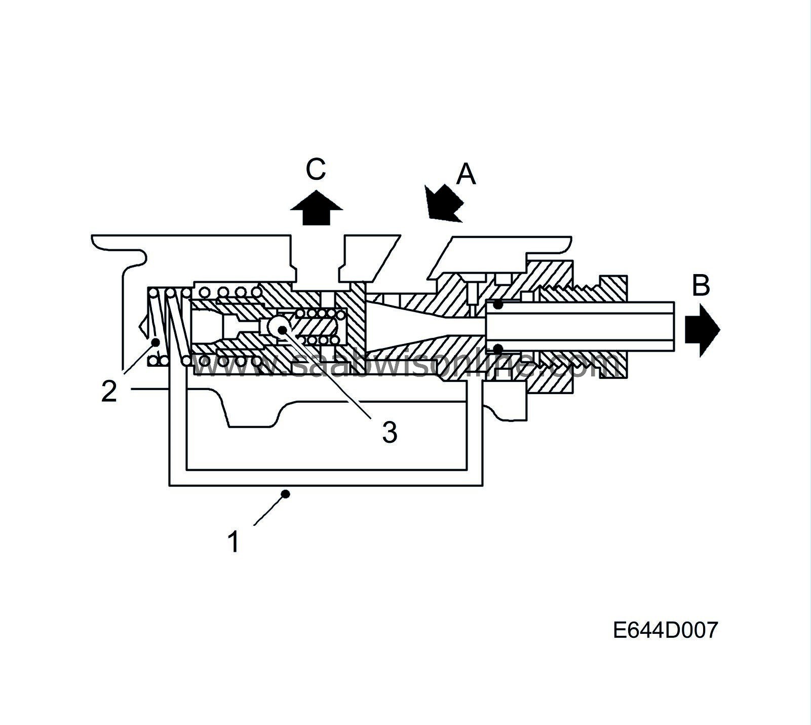
The purpose of the control valve is to regulate the flow from the pump so that it remains constant, regardless of engine/pump rpm.
The control valve sits on one side, directly connected to the pump flow (A). At the outlet passage (B) of the pump, a restrictor is situated from which a connecting passage (1) leads to the other side of the valve, which contains a spring (2). When unactuated, the valve presses against the outlet side. When pressure is high, an overflow valve (3) housed in the control valve is actuated by the power steering fluid pressure on the spring-loaded side of the control valve.
For the control valve to operate, a certain amount of power steering fluid must circulate through it continuously at (A) and (C), although not when the steering wheel is at full lock.
The operating pressure of the pump is 4-120 bar while maximum flow is approx. 7.2 litres per minute.
| Steering and parking at low engine speed |
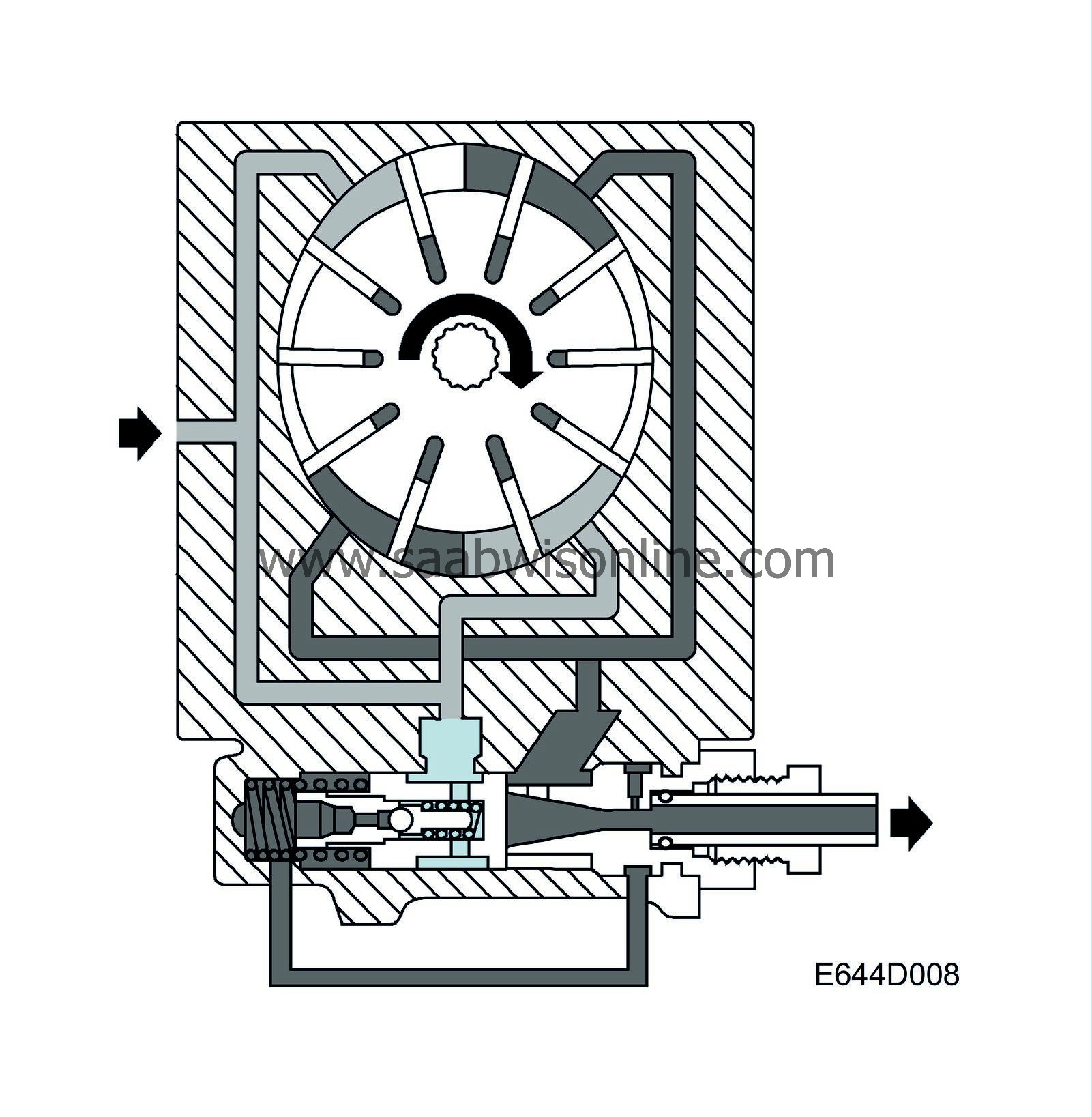
The pressure produced by the pump (dark pattern) is slightly reduced over the restrictor at the pump outlet. The reduced pressure is led to the spring-loaded side of the control valve, at which time there is a minor pressure difference between the two sides of the valve. Due to the low pump speed, however, this pressure difference is not enough to actuate the valve.
| Steering at high engine speed (pump in flow control mode) |
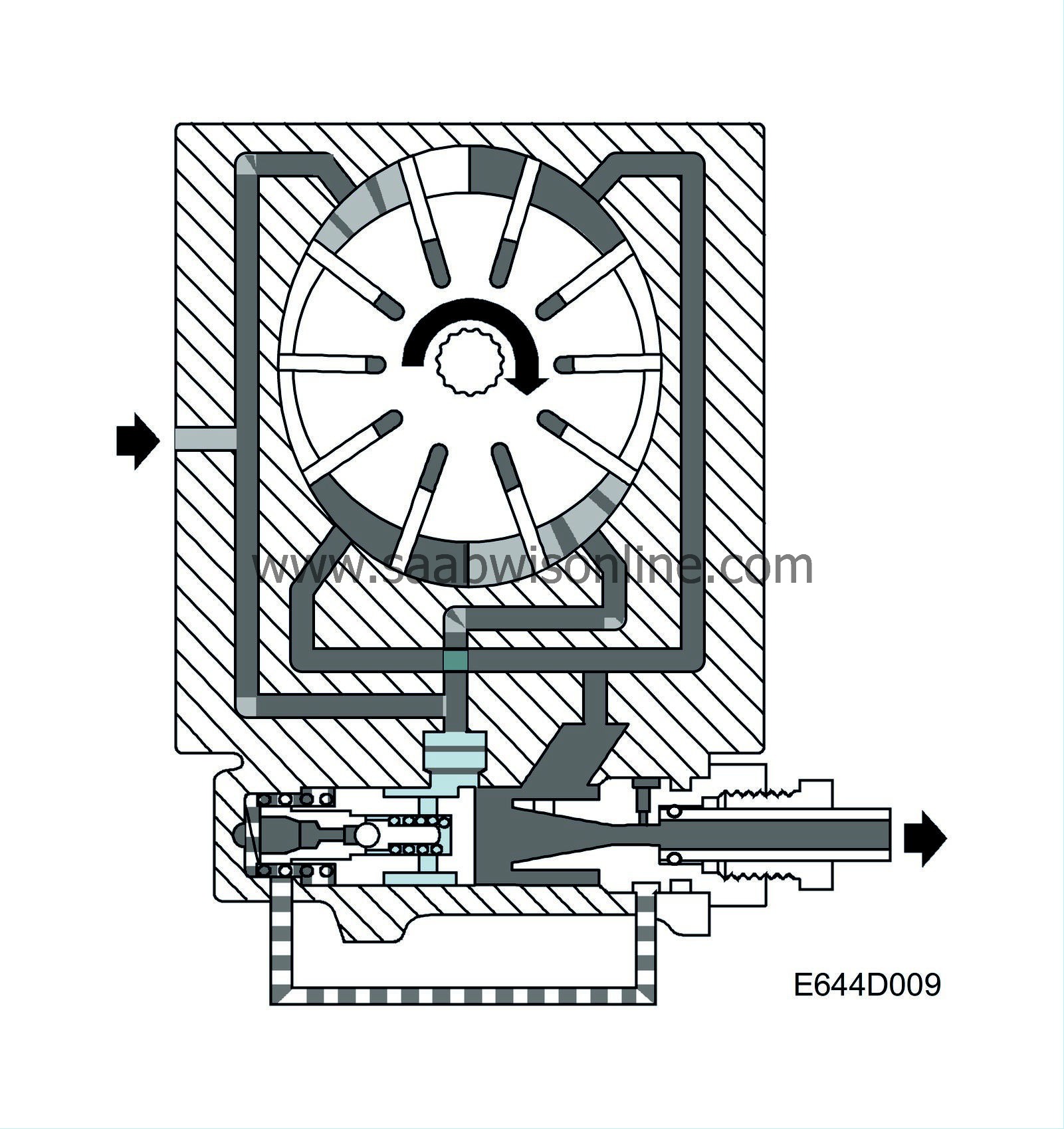
The flow of power steering fluid inside the pump increases with increasing engine rpm and owing to the restrictor in the pump outlet the flow velocity also increases. This reduces the pressure in the connecting passage, with the result that the pressure on the spring-loaded side of the control valve will be lower than that acting on the outlet side of the valve. The valve therefore overcomes the force of the spring, opening a port to the suction side of the pump and allowing a certain amount of internal recirculation of the fluid to take place so that the flow from the pump is maintained at a constant rate, regardless of engine/pump rpm.
| Steering wheel turned to full lock |
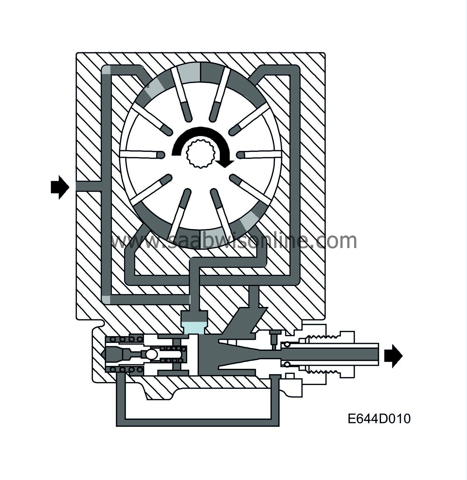
Pump speed in this case is often low. When the steering wheel is turned to full lock the control valve of the steering gear closes. The flow of fluid from the pump will then be zero.
The resulting high pressure is directed via the connecting passage to the spring-loaded side of the control valve. The pressure opens the overflow valve and allows the fluid to pass to the inlet side of the pump. The pressure difference across the control valve forces it to move against the spring and thus open the port for recirculation of the full delivery flow from the pump.
The predetermined maximum pressure is maintained as long as the control valve remains closed.


