Anti-roll bar
| Anti-roll bar |
| To remove |
| 1. |
Raise the car.
|
|
| 2. |
Remove the rear wheels.
|
|
| 3. |
Cars with tyre pressure monitoring:
Remove the rear RH wing liner
.
|
|
| 4. |
Cars with tyre pressure monitoring:
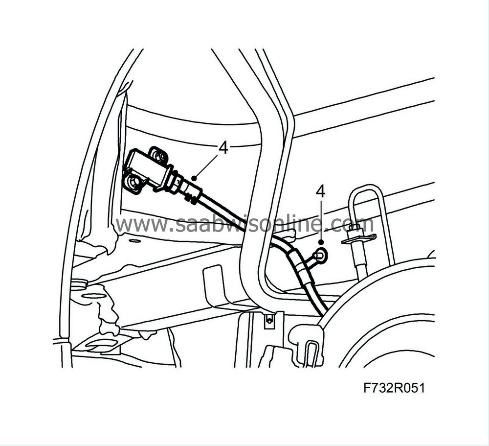
Unplug the connector of the signal detector, release the wheel housing clips and fold down the wiring harness.
|
|
| 5. |
CV:
Remove the chassis reinforcement from the rear subframe
.
Cut the front pipe between the flexihose and the silencer, 87 mm above the silencer. Use 83 95 667 Pipe cutter/exhaust system . See also Silencer, front, A20NFT/LHU . Lift down the rear section of the exhaust system. |
|
| 6. |
Remove the retaining spring from the brake caliper.

|
|
| 7. |
Remove the protective covers.
Remove the hydraulic body and suspend it with a hook in the brake pipe holder.
Remove the outer brake pad. |
|||||||
| 8. |
Remove the hydraulic body on the other side according to steps 6-7.
|
|
| 9. |
Relieve the weight on the shock absorbers on both sides.
Clean the bolts holding the shock absorbers to the steering swivel member and lubricate the threads. Remove the bolts. 
|
|
| 10. |
Open the protective case and unplug the connection for the electrical circuit.

|
|
| 11. |
Place a pillar jack under the centre of the subframe.
|
|
| 12. |
Remove the subframe bolts from the body

|
|
| 13. |
Lower the subframe and lift the springs away.
|
|||||||
| 14. |
Remove the anti-roll bar from the steering swivel members.

|
|
| 15. |
Remove the anti-roll bar mountings from the subframe.
|
|
| 16. |
Lift out the anti-roll bar towards the rear between the subframe and the body.
|
|
| To fit |
| 1. |
Lift the anti-roll bar into place between the subframe and the body.
|
|
| 2. |
Fit the bushes and caps on the subframe.
Fit the anti-roll bar to the subframe. Tightening torque bolt 8 8 (flange diameter 15.2 mm): 18 Nm (13 lbf ft) and use Thread locking adhesive, Loctite 242Tightening torque bolt 10 9 (flange diameter 16.7 mm): 31 Nm (23 lbf ft) 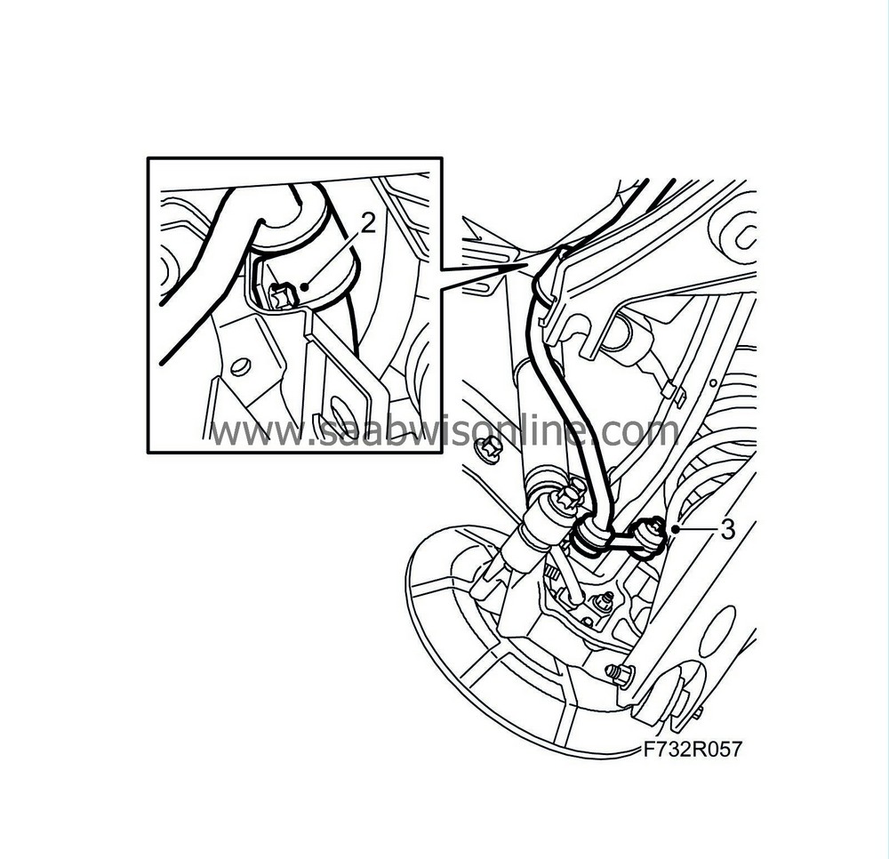
|
|
| 3. |
Fit the anti-roll bar link to the steering swivel member on both sides.
Tightening torque 53 Nm (39 lbf ft) |
|
| 4. |
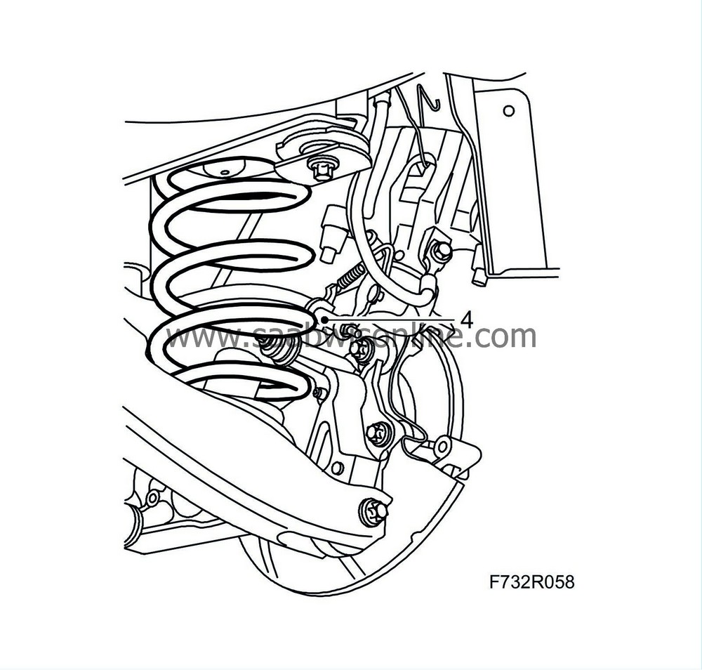
Fit the spring supports on the springs. Place the springs on the lower suspension arms.
|
|
| 5. |
Raise the subframe with a pillar jack, pushing it forward slightly.
|
|||||||
| 6. |
Fit the subframe to the body.
Tightening torque 75 Nm +135° (55 lbf ft +1350°) 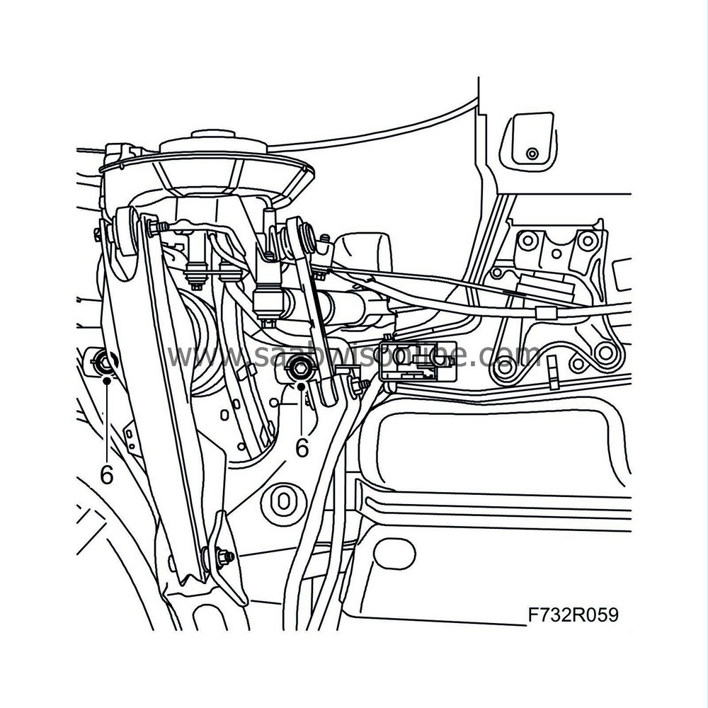
|
|
| 7. |
Remove the jack.
|
|
| 8. |
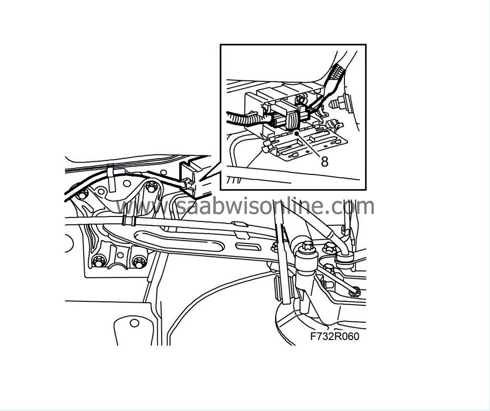
Connect the wiring harness, plug in the connector and close the protective case.
|
|
| 9. |
Lift the steering swivel members and fit the shock absorbers on both sides.
Tightening torque 150 Nm (110 lbf ft)

|
|||||||
| 10. |
Remove the inner brake pad.
Screw in the brake piston with 89 96 969 Resetting tool and 89 96 977 Adapter . 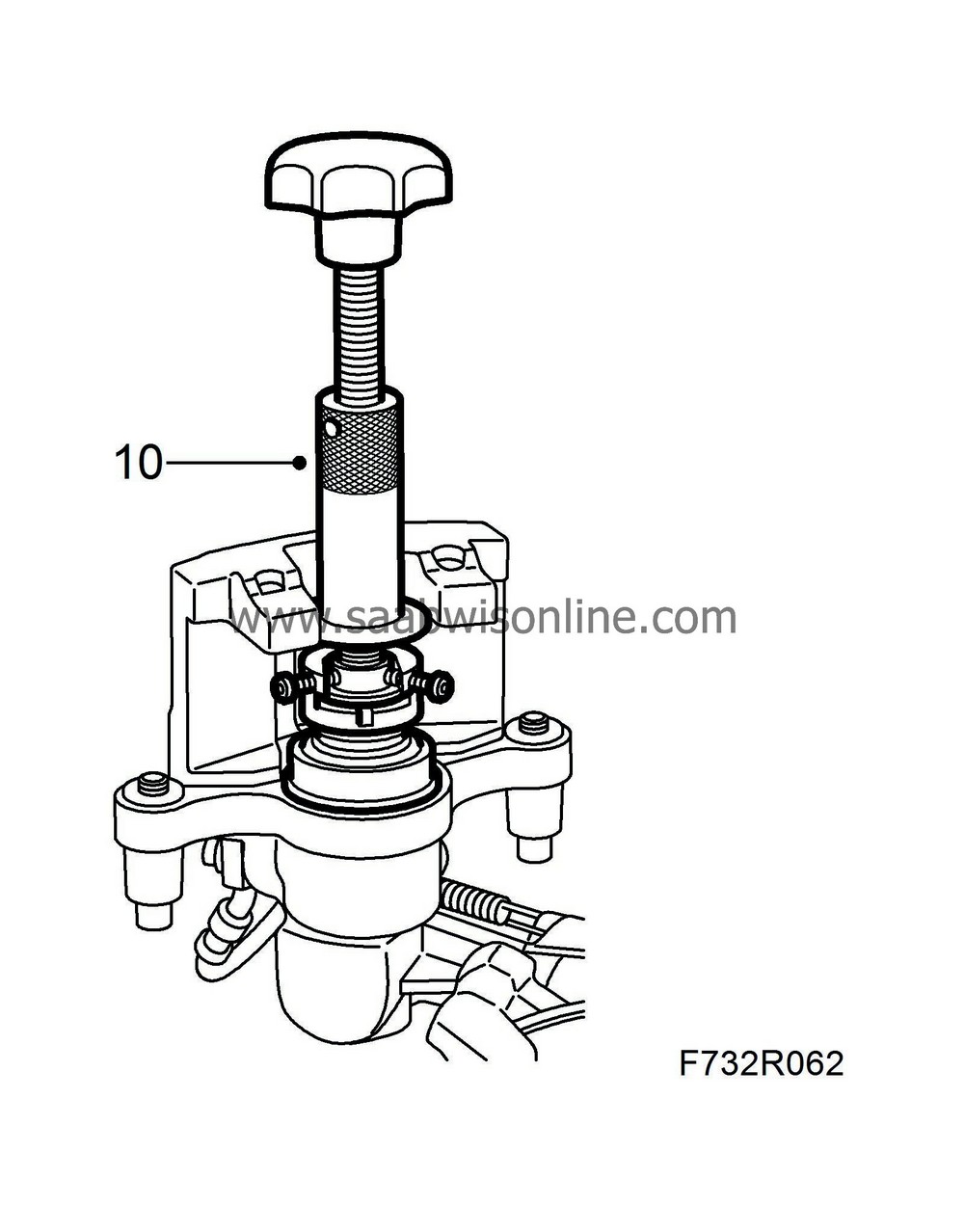
|
|
| 11. |
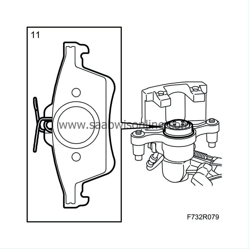
Fit the brake pads.
|
|
| 12. |
Fit the hydraulic body.
Tightening torque 28 Nm (21 lbf ft) Fit the protective covers. Fit the retaining spring to the hydraulic body. 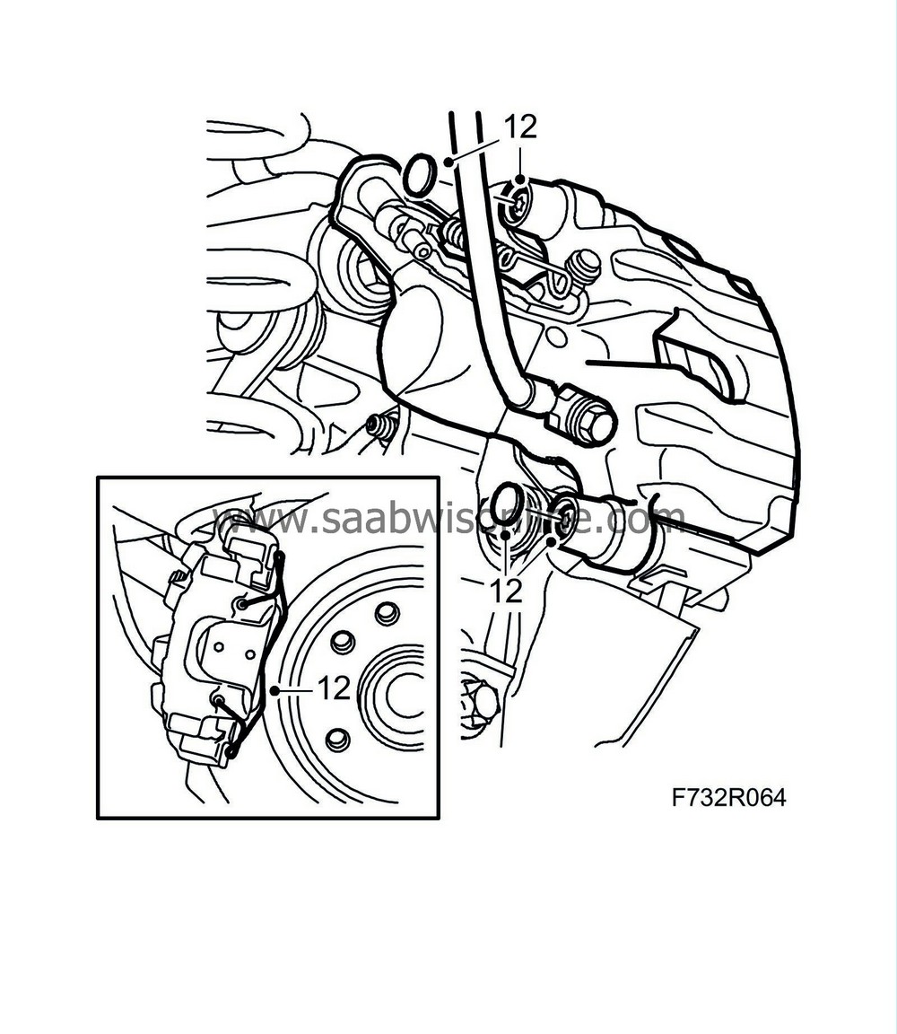
|
|
| 13. |
Repeat steps 10-12 for the other side.
|
|
| 14. |
Clean the exhaust pipe joints and fittings. Fit the pipes with joint clamps. See EPC and
Silencer, front, A20NFT/LHU
.
Tightening torque 40 Nm (30 lbf ft) |
|
| 15. |
CV:
Fit the chassis reinforcement to the rear subframe
.
|
|
| 16. |
Cars with tyre pressure monitoring:
Fit the wiring harness and plug in the connector for the signal detector.
Fit the wing liner
.
|
|
| 17. |
Fit the rear wheels
.
|
|
| 18. |
Lower the car to the floor.
|
|
| 19. |
Depress the brake pedal several times to press out the self adjustment of the brake pistons and the parking brake.
|
|


