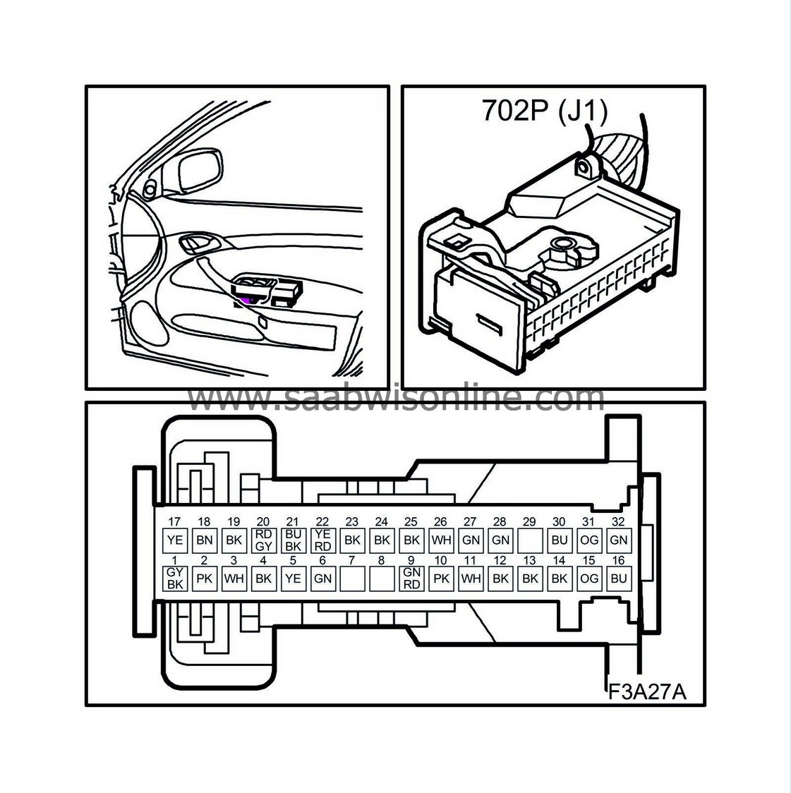
Test readings, passenger door module (702P)
|
|
Test readings, passenger door module (702P)
|
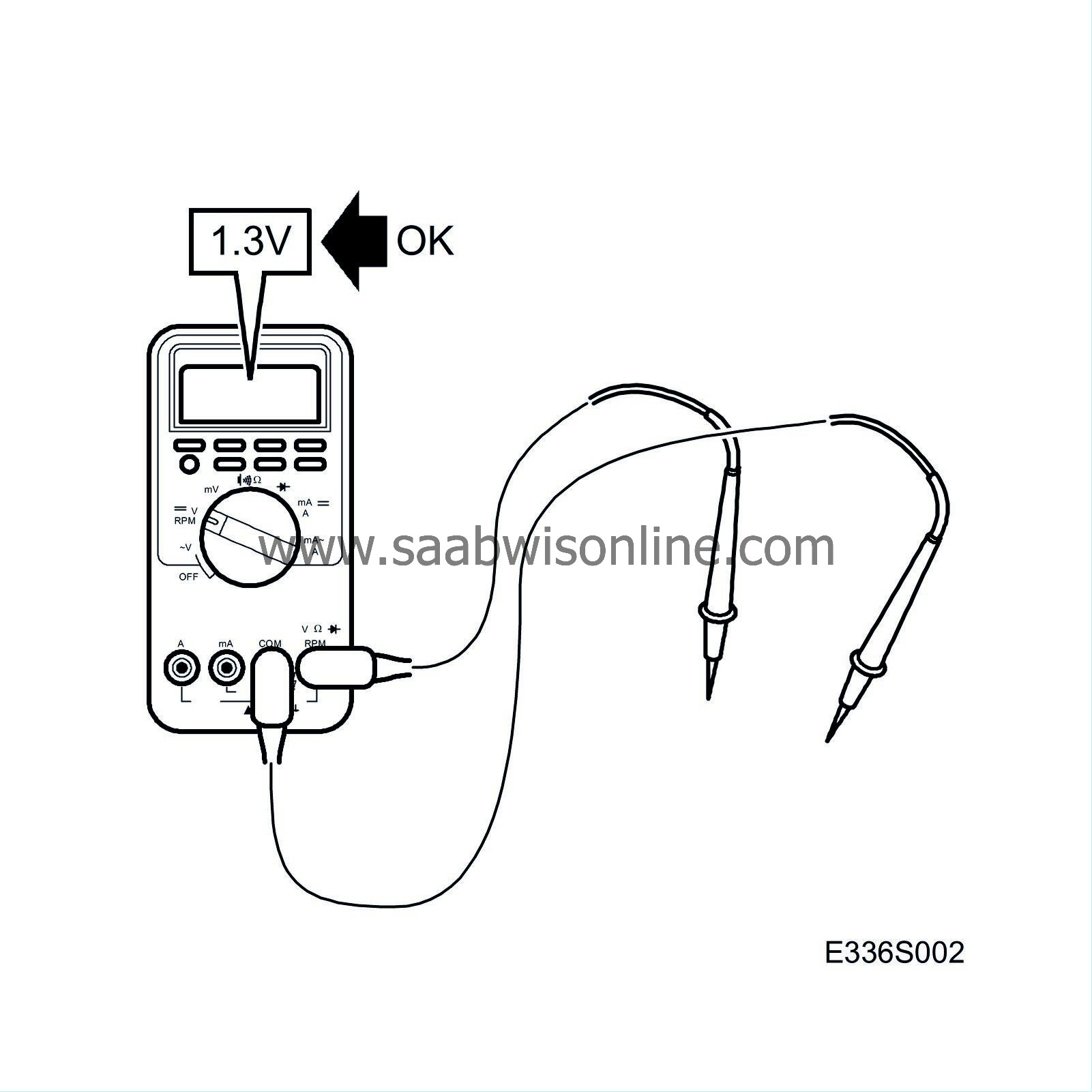 The following pages contain directions and readings for testing signals and levels of the control module.
|
•
|
Observe the test criteria. Use common sense when assessing the test results.
|
|
•
|
Check first that the control module is receiving power and is grounded.
|
|
•
|
Then check all sensor inputs and signals from other systems.
|
|
•
|
Finally, check the control module outputs. Remember that the test readings are not a confirmation of whether the actuator is in working order.
|
|
•
|
If a test reading is incorrect, use the wiring diagram to locate the leads, connectors or components that need to be checked further.
|
|
•
|
Specified readings are for a calibrated Fluke 88/97.
|
|
•
|
Test readings % (+) and ms (+) indicate the signal pulse ratio and pulse width respectively. A scan tool with pulse ratio and pulse width measurement must be used. The sign indicates positive trigger pulse, TRIG+.
|
|
Note
|
|
All units on the I and P-buses send signals.
|
|
Control module pin
|
Component/
function
|
IN/OUT
|
Test criteria
|
|
Measure across
|
Test reading
|
|
1
|
Activation power door mirror right/left
|
IN/OUT
|
Ignition ON
|
|
1-J2-7
|
B+
|
|
2
|
Activation power door mirror up/down
|
IN/OUT
|
Ignition ON
|
|
2-J2-7
|
B+
|
|
3
|
Not connected
|
|
|
|
|
|
|
4
|
Ground, (logic)
|
IN
|
Ignition ON
|
|
4-B+
|
B+
|
|
5
|
Power supply, hall sensor
|
IN
|
Ignition ON
|
|
6-J2-7
|
4.6-4.7V
|
|
6-8
|
Not connected
|
|
|
|
|
|
|
9
|
Hall sensor 2
|
IN
|
Ignition ON
|
Express activated
|
9-5
|
6.3-6.4 AC
|
|
10
|
Rheostat
|
IN
|
Ignition ON
|
Increase from MIN to MAX
|
10-(J2-7)
|
4-12V
|
|
11
|
Power mirror, horizontal position
|
IN
|
Ignition ON
|
Between end positions
|
11-21
|
0.8-4V
|
|
12
|
Central locking system, lock/unlock
|
OUT
|
Door closed, ignition OFF
|
|
12-(J2-7)
|
4.6-4.7V
|
|
13
|
TSL sensor
|
IN
|
Ignition ON
|
|
13-(J2-7)
|
11V
|
|
14
|
Sensor, central locking system lock/unlock
|
IN
|
Ignition ON
|
|
14-(J2-7)
|
1.86V
|
|
15
|
Power mirror, vertical position
|
IN
|
Ignition ON
|
Between end positions
|
15-21
|
0.7-3.8V
|
|
16
|
Hall sensor 1
|
IN
|
Ignition ON
|
Express activated
|
16-5
|
6.3-6.4 AC
|
|
17
|
Common activation, power mirror
|
OUT
|
Ignition ON
|
|
17-J2-7
|
B+
|
|
18
|
Extending power mirror
|
OUT
|
Ignition ON
|
Extend power mirror
|
18-31
|
B+
|
|
19
|
Central locking system, lock/unlock
|
OUT
|
Ignition ON
|
Door closed, ignition OFF
|
19-(J2-7)
|
Lock 12V for <0.2s
Unlock 4.5V for <0.2s
|
|
20
|
+30 voltage logic
|
OUT
|
Ignition ON
|
|
20-(J2-7)
|
B+
|
|
21
|
Power supply, potentiometer
|
IN
|
Ignition ON
|
|
21-30
|
4.76V
|
|
22
|
Ground, hall sensor
|
OUT
|
|
|
22-5
|
4.76V
|
|
23
|
Central locking system, lock/unlock
|
OUT
|
|
Door closed, ignition OFF
|
23-(j2-7)
|
Lock 0.3V for <0.2s
Unlock 12V for <0.2s
|
|
24
|
Sensor ground, central locking system
|
OUT
|
Ignition ON
|
|
24-32
|
4.10V
|
|
25
|
TSL activation
|
OUT
|
|
Door closed, ignition OFF
|
25-(J2-7)
|
Lock 6V for <0.2s
Unlock 5.2V for <0.2s
|
|
26
|
Not connected
|
|
|
|
|
|
|
27
|
Courtesy lighting
|
IN
|
Ignition ON
|
|
27-(J2-7)
|
B+
|
|
28
|
I-bus
|
OUT
|
Ignition ON
|
Use
86 11 857 Test lamp, red/green
|
28-(J2-7)
|
Test lamp should flash
|
|
29
|
Not connected
|
|
|
|
|
|
|
30
|
Potentiometer ground
|
OUT
|
Ignition ON
|
|
30-21
|
4.75V
|
|
31
|
Contracting power mirror
|
OUT
|
|
Contract power mirrors
|
31-18
|
B+
|
|
32
|
Door switch
|
IN
|
Ignition ON
|
|
32-(J2-7)
|
4.10V
|
|
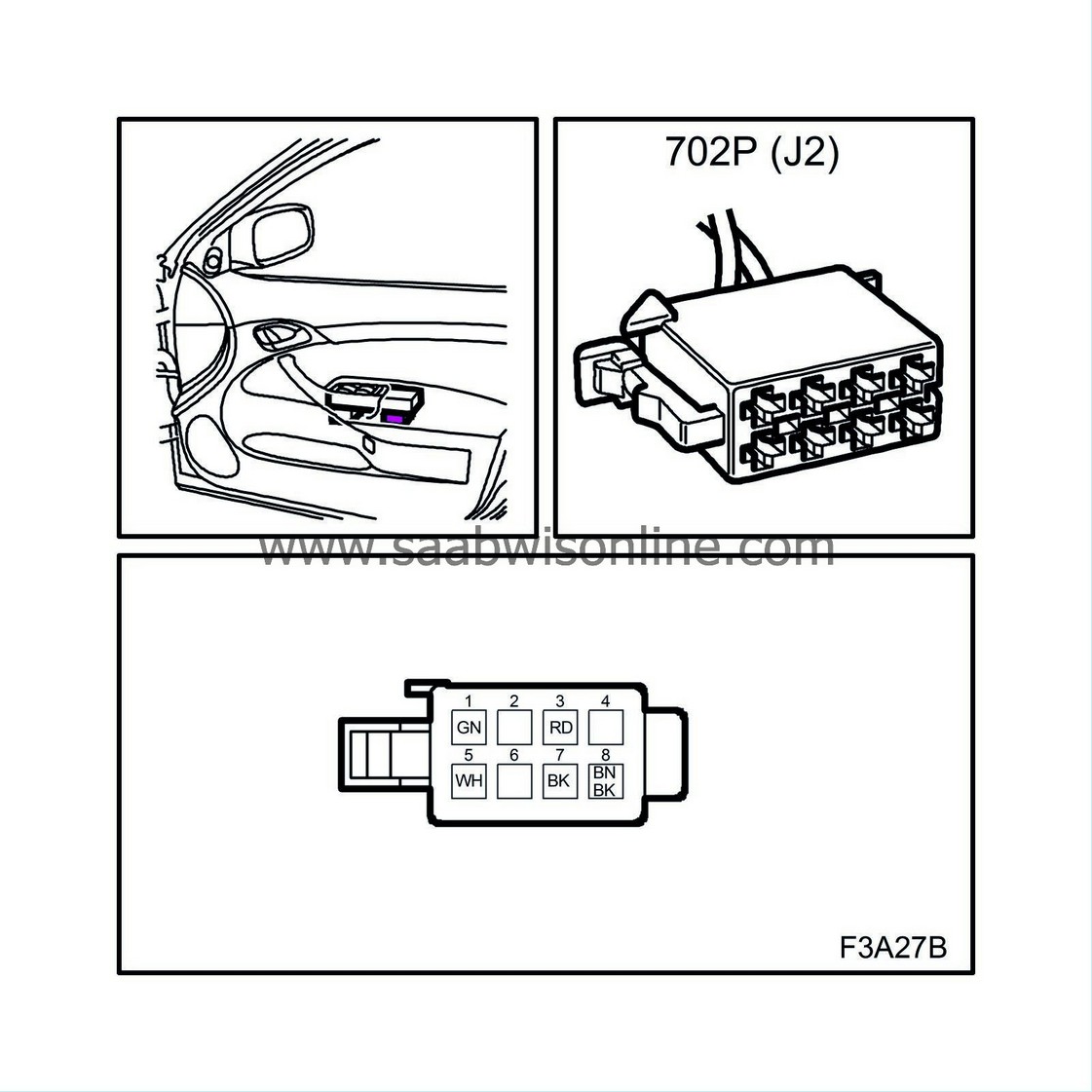
Pin
|
Component/
function
|
IN/OUT
|
Test criteria
|
|
Measure across
|
Test reading
|
|
1
|
Window lift, up
|
IN
|
Ignition ON
|
Close window
|
1-7
|
B+
|
|
2
|
Not connected
|
|
|
|
|
|
|
3
|
+30 voltage
|
IN
|
Ignition ON
|
|
3-7
|
B+
|
|
4
|
Not connected
|
|
|
|
|
|
|
5
|
Window lift, down
|
IN
|
Ignition ON
|
Open window
|
5-7
|
B+
|
|
6
|
Not connected
|
|
|
|
|
|
|
7
|
Ground
|
OUT
|
Ignition ON
|
|
7-3
|
B+
|
|
8
|
Activation of power mirror heating
|
OUT
|
Ignition ON
|
Mirror heating activated
|
8-7
8-7
|
0V
B+
|


