Cylinder Head Assemble (LF1, LFW or LFX)
| Cylinder Head Assemble (LF1, LFW or LFX) |
Special Tools
| • |
EN 8062
Valve Spring Compressor - Head Off
|
|
| • |
EN 46116
Valve Stem Seal Remover/Installer
|
|
| • |
EN 46117
Valve Stem Key Remover/Installer
|
|
| • |
EN 46119
Off-Vehicle Valve Spring Compressor Adapter
|
|
| • |
EN 46122
Camshaft Position Actuator Check-Ball Valve Remover/Installer
|
|
For equivalent regional tools, refer to Special Tools .
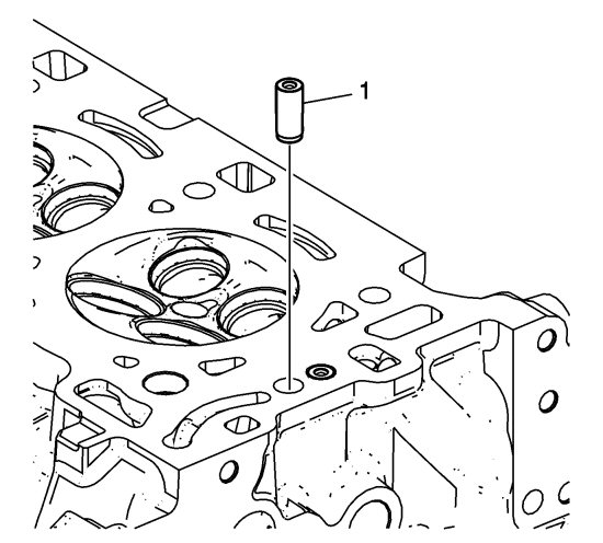
| 1. |
Use lubricant included with
EN 46122
remover/installer to lubricate outside of new check valve (1).
|
|
| 2. |
With the check ball end of the check valve facing UP, away from the head, insert the NEW check valve into the check valve bore in the cylinder head.
|
|
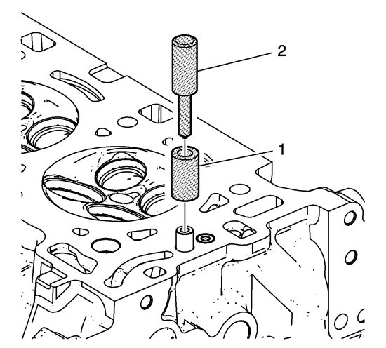
| 3. |
Place collar EN 46122-2 (1) over the new check valve with the slightly-larger inside diameter of the collar DOWN toward the cylinder head.
|
|
| 4. |
Using the driver EN 46122-1 (2), lightly tap the new check valve into place until the driver stops against the top of the collar.
|
|
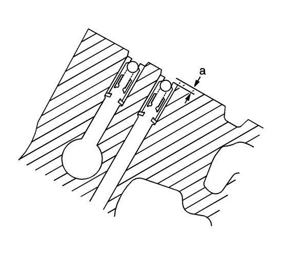
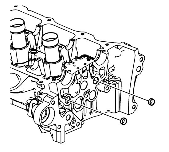
| 5. |
Inspect the camshaft position actuator oil feed check valves in order to ensure they are properly installed in the cylinder head. The camshaft position actuator oil feed check valve should be flush to 2 mm (0.0787 in) below the cylinder head deck surface (a).
|
|
| 6. |
Refer to
Fastener Caution
.
Install the cylinder head coolant threaded plugs and tighten to 31 Nm (23 lb ft) . 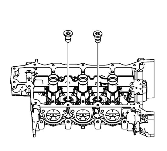
|
|
| 7. |
Install the NEW cylinder head oil gallery expansion plugs.
|
|
| 8. |
Place the valve stem oil seals onto the guides.
|
|
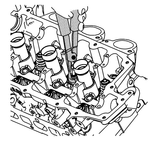
| 9. |
Mount a new valve stem oil seal using the EN 46116 remover/installer. |
|||||||
| 10. |
Push and twist the valve stem oil seal into position on the valve guide until the seal positively locks on the guide using the EN 46116 remover/installer. |
|||||||
| 11. |
Lubricate the valve stem and valve guide ID with clean engine oil. Refer to
Adhesives, Fluids, Lubricants, and Sealers
for recommended lubricant.
|
|
| 12. |
Insert the valve into the valve guide until it bottoms on the valve seat. 
|
|||||||
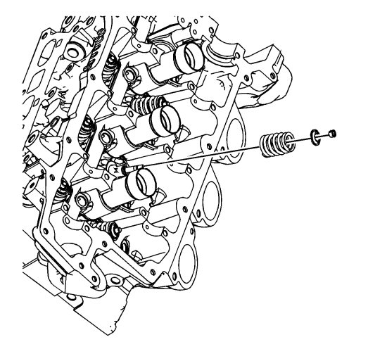
| 13. |
Position the valve spring on the spring seat.
|
|
| 14. |
Place the valve spring retainer onto the valve spring.
|
|
| 15. |
Compress the valve spring using the EN 8062 compressor and the EN 46119 adapter. 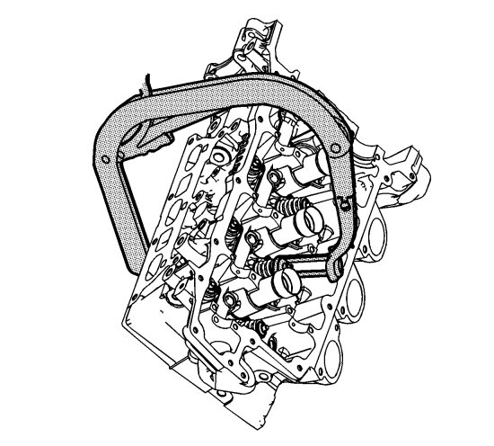
|
|||||||||||||||||
 Warning
| 16. |
With the spring compressed, install the valve keepers into the EN 46117 remover/installer. 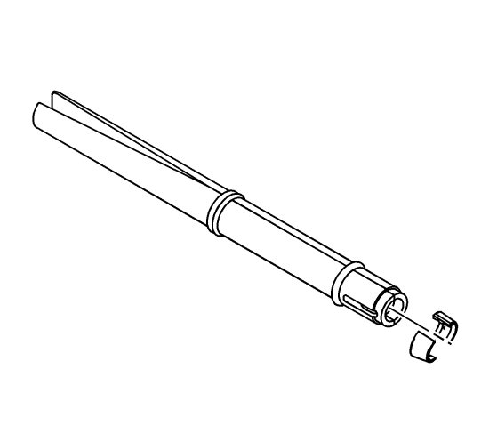
|
|||||||
| 17. |
Place the keepers into position by pushing the tool downward. Hold together the tool lightly in the area between the O-rings with the thumb and forefinger, then release the tension on the adapter
EN-46119
and
compressor
EN 8062 . In this way, the remover/installer
EN-46117
is pressed slowly from the valve stem and the collets are left in place.
|
|
| 18. |
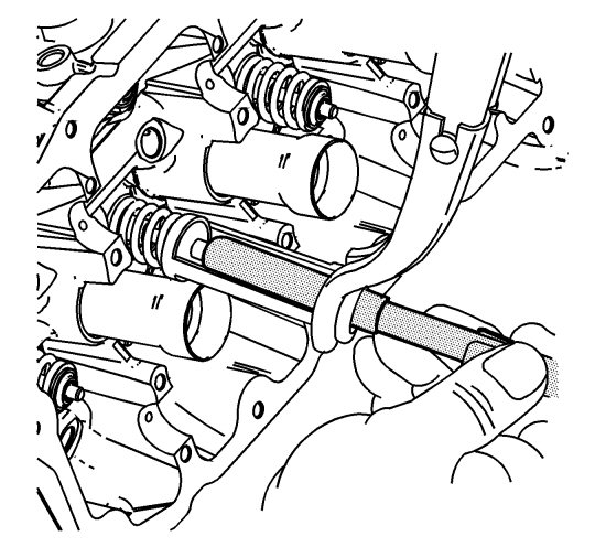
Verify that the valve keepers are installed by placing a rag over the valve tip and tapping with a dead-blow hammer.
|
|
| 19. |
Install the fuel rail with injectors (2) into the cylinder head evenly. 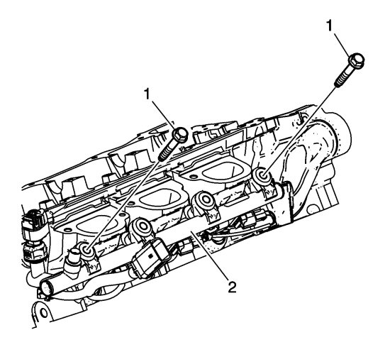
|
|||||||
| 20. |
Install and hand tighten the two outer fuel rail bolts (1) to seat the injectors in the injector bores.
|
|
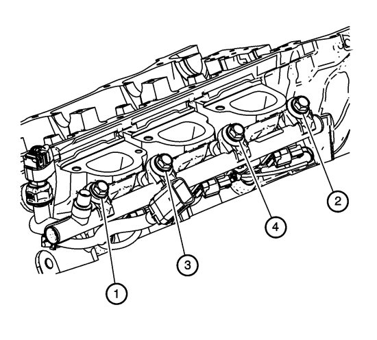
| 21. |
Install and hand tighten the two inner fuel rail bolts.
|
|
| 22. |
Tighten the fuel rail bolts in the sequence shown to
25 Nm (18 lb ft)
.
|
|
This project is supported by memberships and donations. If you use this site, please consider Joining SCNA and/or making a donation.
Our Friends
