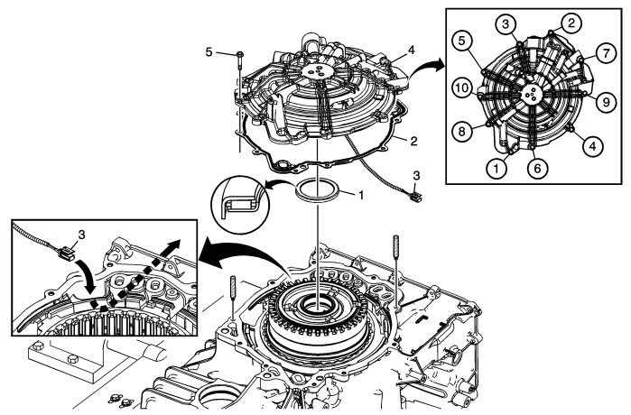
Case Cover Assembly Installation
|
|
Case Cover Assembly Installation
|
|
Callout
|
Component Name
|
|
1
|
Input Shaft Thrust Bearing
|
Note
|
|
Note location of the orientation lip on bearing. All thrust bearings can only be assembled one way.
|
|
|
2
|
A/Trans Case Cover Gasket
|
|
3
|
Input Speed Sensor Wire Harness
|
Note
|
|
Route the input speed sensor wire harness through the case passage.
|
|
|
4
|
A/Trans Case Cover Assembly
Procedure
|
1.
|
Use guide pins to install the case cover assembly to prevent damage to the input shaft thrust bearing.
|
|
2.
|
Pull the input speed sensor wire harness through the case passage while lowering the cover assembly onto the case.
|
Special Tools
39068
Guide Pins
For equivalent regional tools, refer to
Special Tools
.
|
|
5
|
A/Trans Case Cover Assembly Bolt M6 x 30 (Qty: 10)
Refer to
Fastener Caution
.
Procedure
Tighten in sequence shown.
Tighten
12 Nm (106 lb in)
|


