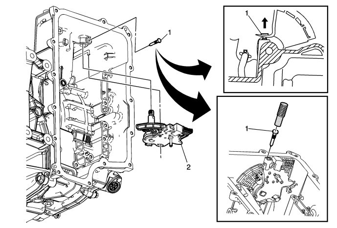
Manual Shift Detent Lever with Shaft Position Switch Assembly Replacement
|
|
Manual Shift Detent Lever with Shaft Position Switch Assembly Replacement
|

|
Callout
|
Component Name
|
Preliminary Procedures
|
|
1
|
Manual Shaft Detent Lever Pin
 Warning
|
|
Use J 41229 to install the manual shaft pin at the correct height in order to properly secure the manual shaft. If you install the pin too deep, the case bore may crack.
|
|
|
|
|
|
|
Note
|
|
•
|
Use a small nail puller to remove the pin. Discard the pin. It is not reusable.
|
|
•
|
Use
DT-41229
Manual Shaft Pin Installer to install the pin.
Inspect that the pin installed height is within 6.5 mm-7.5 mm (0.25 in-0.30 in).
|
Special Tools
DT 41229
Manual Shaft Pin Installer
|
|
2
|
Manual Shaft Detent Lever Assembly (With Shift Position Switch)
Procedure
|
•
|
Removal: Partly lower the manual shaft detent lever assembly (w/shift position switch) in order to rotate the detent lever and disconnect the park actuator rod. Then fully remove the manual shaft detent lever assembly from the transmission case.
|
|
•
|
Installation: Partly install the manual shaft detent lever assembly (w/shift position switch). Rotate the detent lever and connect the park actuator rod. Then fully install the manual shaft detent lever assembly in the transmission case.
|
|
•
|
Lubricate the manual shaft with automatic transmission fluid (ATF) to prevent damage to the manual shift shaft seal.
|
|
Note
|
|
Do not pull the park actuator rod end out beyond the machined oil passage surface in the case. A no park condition will exist if the park pawl actuator assembly is pulled out of the transmission too far and the actuator rod disengages from the park pawl. The transmission assembly will require disassembly to re-install the actuator rod over the park pawl.
|
|


 Warning

