Master Cylinder Replacement
| Master Cylinder Replacement |
| Removal Procedure |
Refer to Brake Fluid Irritant Warning .
Refer to Brake Fluid Effects on Paint and Electrical Components Caution .
| 1. |
Turn the ignition switch to the OFF position.
|
|
| 2. |
Apply the brake pedal several times until the brake pedal becomes firm to deplete the power vacuum brake booster vacuum reserve.
|
|
| 3. |
Using a suitable tool, remove and properly discard the brake fluid from the master cylinder reservoir.
|
|
| 4. |
Without draining the coolant and without disconnecting the hoses, remove and position aside the radiator surge tank. Refer to
Radiator Surge Tank Replacement (LAU)
Radiator Surge Tank Replacement (LF1)
.
|
|
| 5. |
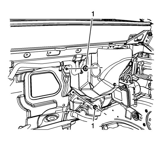
If equipped with the master cylinder heat shield, remove the master cylinder heat shield nuts (1). 
|
|||||||
| 6. |
Remove the master cylinder heat shield bolt (1).

|
|
| 7. |
Remove the master cylinder heat shield.
|
|
| 8. |
Disconnect the master cylinder fluid level indicator switch electrical connector.
|
|
| 9. |
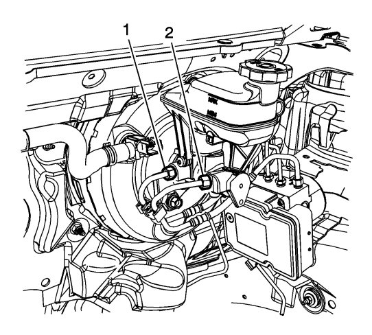
Disconnect the master cylinder primary brake pipe fitting (1).

|
|
| 10. |
Cap the brake pipe fitting and plug the master cylinder outlet port to prevent brake fluid loss and contamination.
|
|
| 11. |
Disconnect the master cylinder secondary brake pipe fitting (2).
|
|
| 12. |
Cap the brake pipe fitting and plug the master cylinder outlet port to prevent brake fluid loss and contamination.
|
|
| 13. |
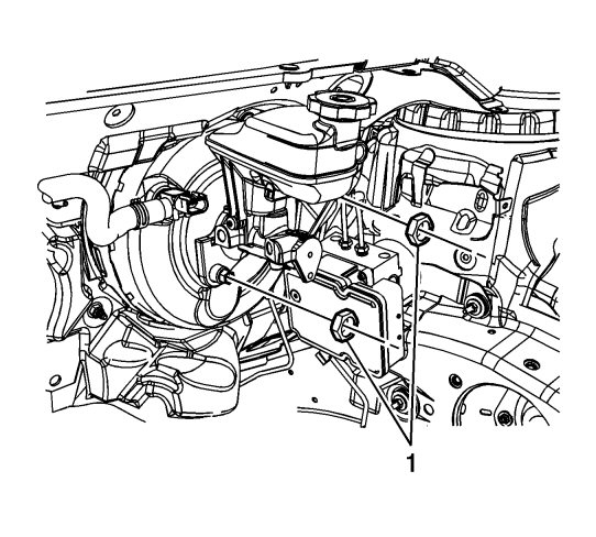
Remove the master cylinder nuts (1).

|
|
| 14. |
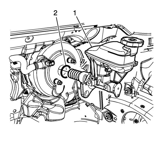
Remove the master cylinder (1).

|
|
| 15. |
Remove the master cylinder O-ring seal (2).
|
|
| Installation Procedure |
| 1. |
If installing a new master cylinder, bench bleed the master cylinder. Refer to
Master Cylinder Bench Bleeding
.
|
|
| 2. |
Install the master cylinder (1) and master cylinder O-ring seal (2). 
|
|||||||
| 3. |
Refer to
Fastener Caution
.
Install the master cylinder nuts (1) and tighten to 50 Nm (37 lb ft) . 
|
|
| 4. |
Connect the master cylinder primary brake pipe fitting (1) and tighten to
19 Nm (14 lb ft)
.

|
|
| 5. |
Connect the master cylinder secondary brake pipe fitting (2) and tighten to
19 Nm (14 lb ft)
.
|
|
| 6. |
Connect the master cylinder fluid level indicator switch electrical connector.
|
|
| 7. |
Install the master cylinder heat shield, if equipped.
|
|
| 8. |
Install the master cylinder heat shield bolt (1) and tighten to
10 Nm (89 lb in)
.

|
|
| 9. |
Install the master cylinder heat shield nuts (1) and tighten to 25 Nm (18 lb ft) . 
|
|||||||
| 10. |
Install the radiator surge tank. Refer to
Radiator Surge Tank Replacement (LAU)
Radiator Surge Tank Replacement (LF1)
.
|
|
| 11. |
Bleed the hydraulic brake system. Refer to
Hydraulic Brake System Bleeding (Manual)
Hydraulic Brake System Bleeding (Pressure)
.
|
|


