Front Compartment Front Half Rail Replacement
| Front Compartment Front Half Rail Replacement |
| Removal Procedure |
Refer to Approved Equipment for Collision Repair Warning .
Refer to Glass and Sheet Metal Handling Warning
| Note | ||
|
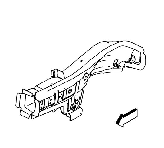
The service part is developed from a complete assembly and will require the spot weld removal at the rail mid joint. The lower rail service part comes as a complete front rail assembly, including all the brackets and the reinforcements. |
| 1. |
Support the engine and the transmission with suitable equipment. 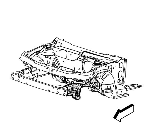
|
|||||||
| 2. |
Remove the fasteners to the engine and the transmission.
|
|
| 3. |
Remove all the other related panels and components as necessary, including the suspension and the crossmember.
|
|
| 4. |
Visually inspect the damaged area. Repair as much of the damage as possible to factory specifications. Refer to
Dimensions - Body
.
|
|
| 5. |
Remove the sealers and anti-corrosion materials from the repair area, as necessary.
|
|
| 6. |
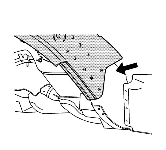
Locate the area where the front compartment will be separated from the rail.
|
|
| 7. |
Locate and drill the factory welds along the flanges of the rail, only up to and including the rail mid joint just forward of the dash panel.

|
|
| 8. |
Drill out the factory welds.
|
|
| 9. |
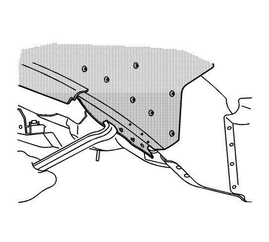
Pry open the outer layer of the rail at the front rail mid joint to allow the front portion of the rail to be removed from the vehicle.
|
|
| 10. |
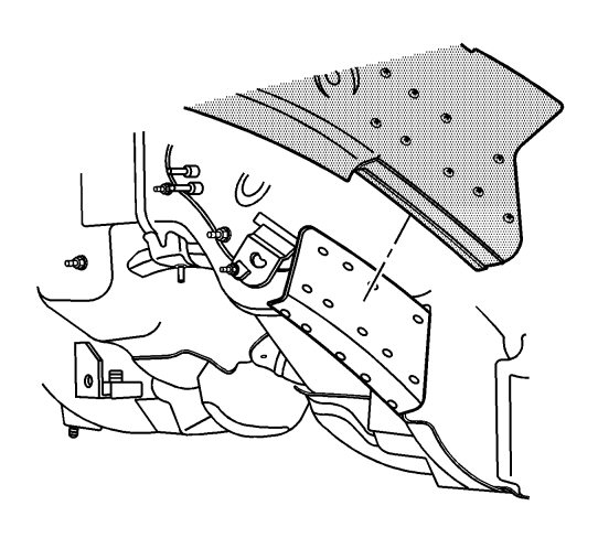
Remove the damaged front lower rail.
|
|
| 11. |
Drill out the factory welds at the service rail assembly mid joint.

|
|
| 12. |
Remove the forward portion of the front rail assembly at the mid joint.
|
|
| 13. |
Prepare the mating surfaces as necessary.
|
|
| 14. |
Apply GM-approved Weld-Thru Coating or equivalent to all mating surfaces. Refer to
Anti-Corrosion Treatment and Repair
.
|
|
| Installation Procedure |
| 2. |
Prepare all mating surfaces as necessary.
|
|
| 3. |
Apply GM-approved Weld-Thru Coating or equivalent to all mating surfaces.
|
|
| 4. |
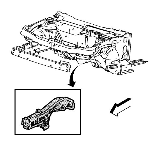
Position the rail to the vehicle.
|
|
| 5. |
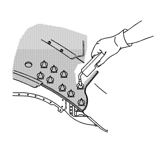
Plug weld accordingly.
|
|
| 6. |
Clean and prepare all welded surfaces.
|
|
| 7. |
Install all related panels and components.
|
|
| 8. |
paint the repaired surface. See
Basecoat/Clearcoat Paint Systems
|
|
| 9. |
Connect the negative battery cable. Refer to
Battery Negative Cable Disconnection and Connection
.
|
|
| 10. |
Activate the SIR system. See
SIR Disabling and Enabling
.
|
|


