To assemble the engine
| To assemble the engine |
| 1. |
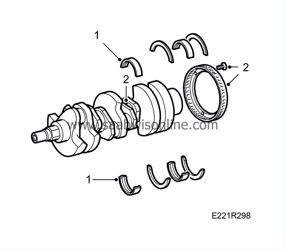
Fit all main bearings in position and oil them.
|
|
| 2. |
Fit the slotted ring. Lock the bolts with part No. (10) 74 96 268. Place the crankshaft in position.
|
||||||||||
| 4. |
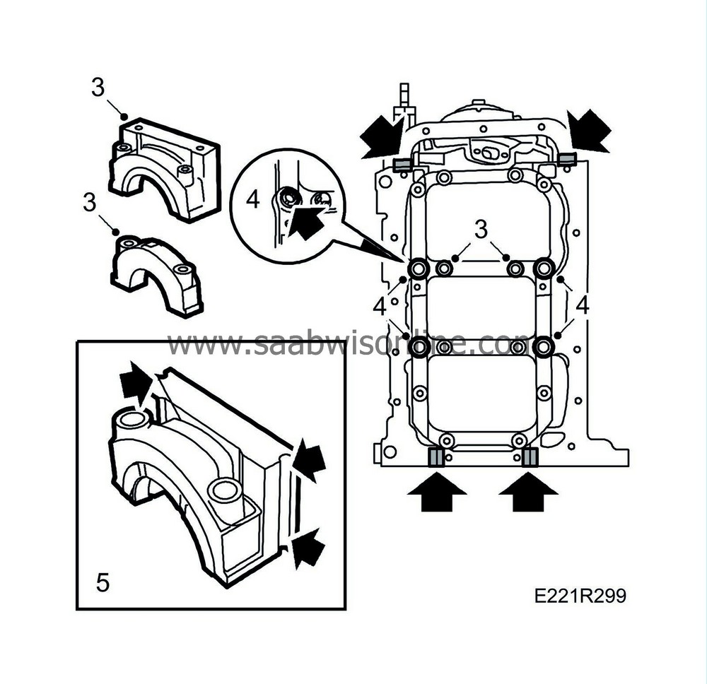
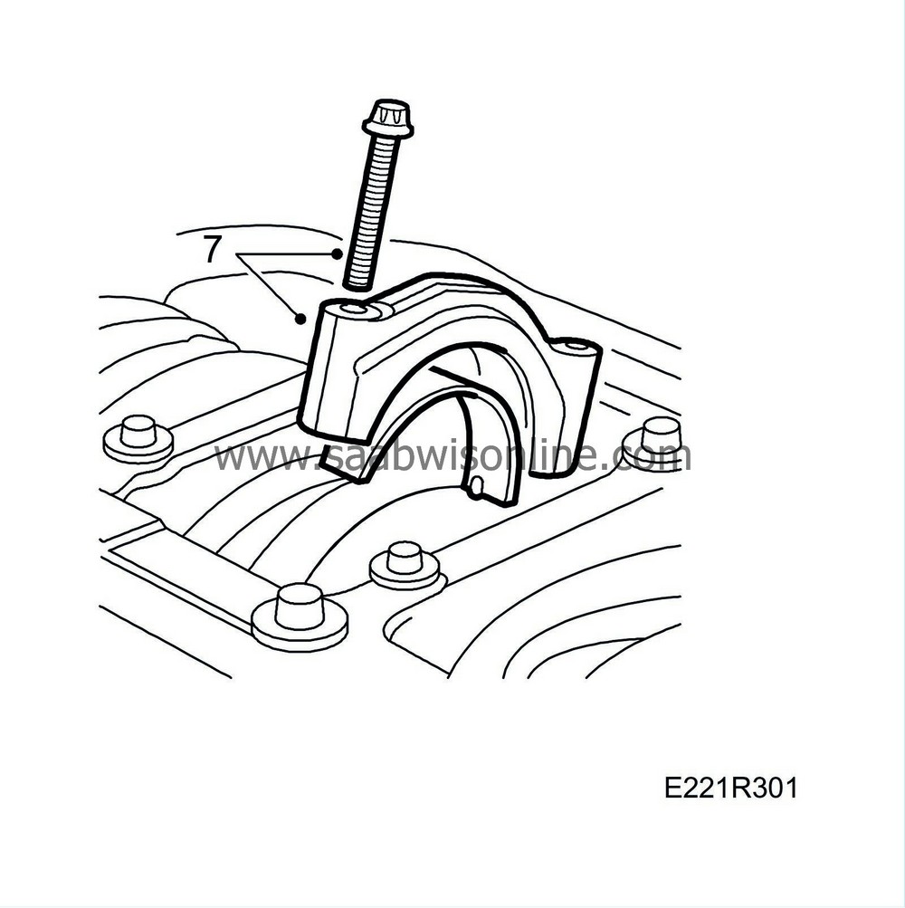
Screw the adjuster sleeves down flush. Coat the main bearing member bolts with part No. (10) 74 96 268 and tighten them.
Tightening torque: 20 Nm (15 lbf ft) |
|
| 5. |
Spray part No. (10) 81 52 381 into the mating joints at the rear main bearing. Do not stop until the compound is forced out at the sides.
|
|
| 8. |
Fit a new rear crankshaft seal using tools 83 94 967 and 83 94 975. Fit the drive plate. Coat the bolts with part no. (10) 74 96 292.
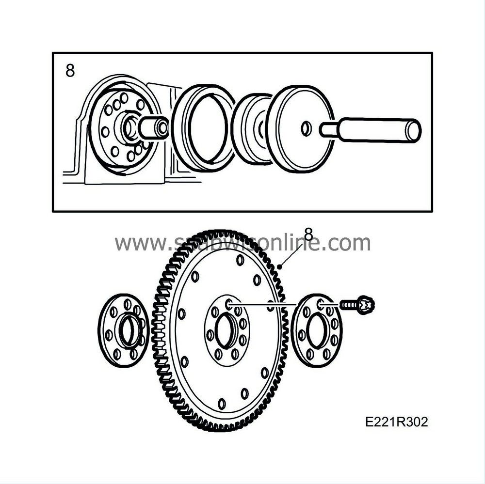
Tightening torque: 65 Nm (48 lbf ft) + 30° |
|
| 9. |
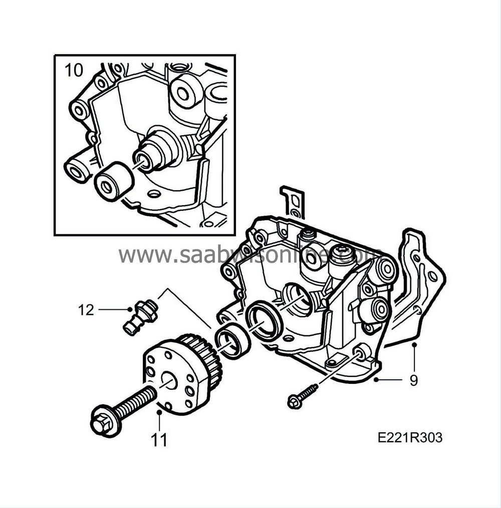
Fit the oil pump with a new gasket. Coat the gasket with part No. (10) 93 21 795.
|
|
| 10. |
Fit a new front crankshaft seal. Use tool 83 94 942.
|
|
| 11. |
Fit counterstay 83 95 063. Coat the back of the camshaft belt sprocket with part no. (10) 93 21 795 and tighten the sprocket.
Tightening torque: 250 Nm (184.5 lbf ft) + 45° |
|
| 12. |
Connect the oil pressure sensor.
|
|
| 13. |
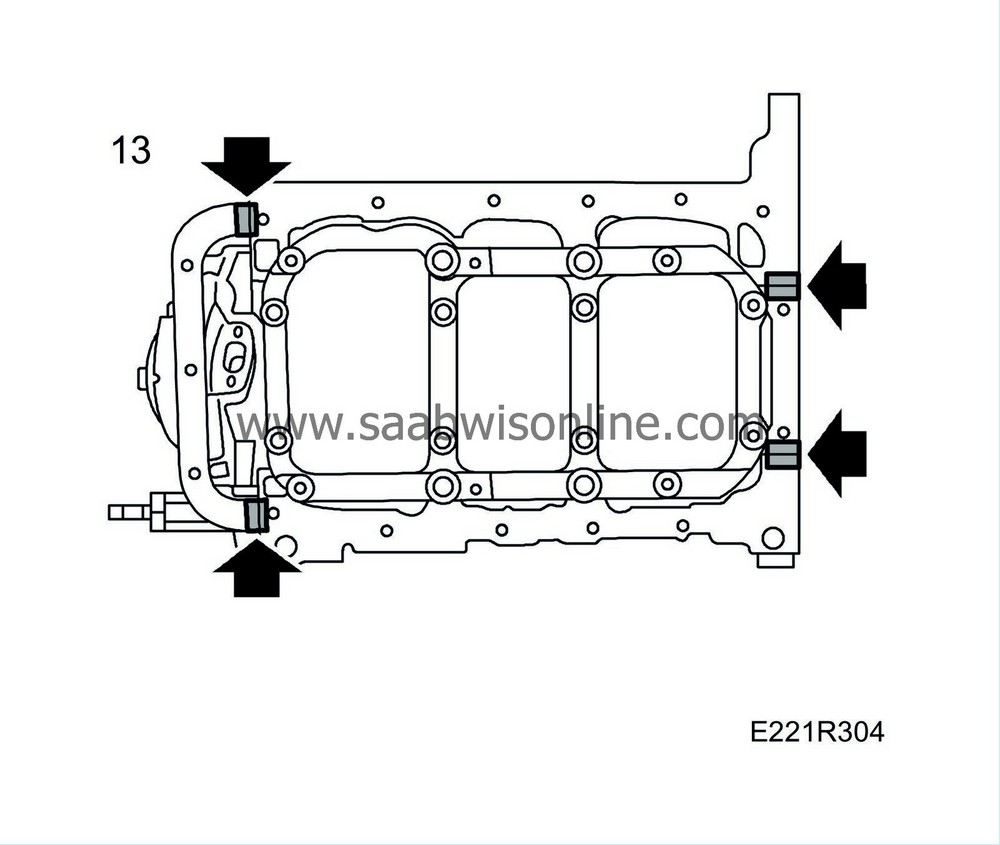
Turn the engine. Apply part No. (10) 81 52 381 to the mating joints.
|
|
| 14. |
Fit the oil antislosh baffle. Lock the bolts with part No. (10) 74 96 268.
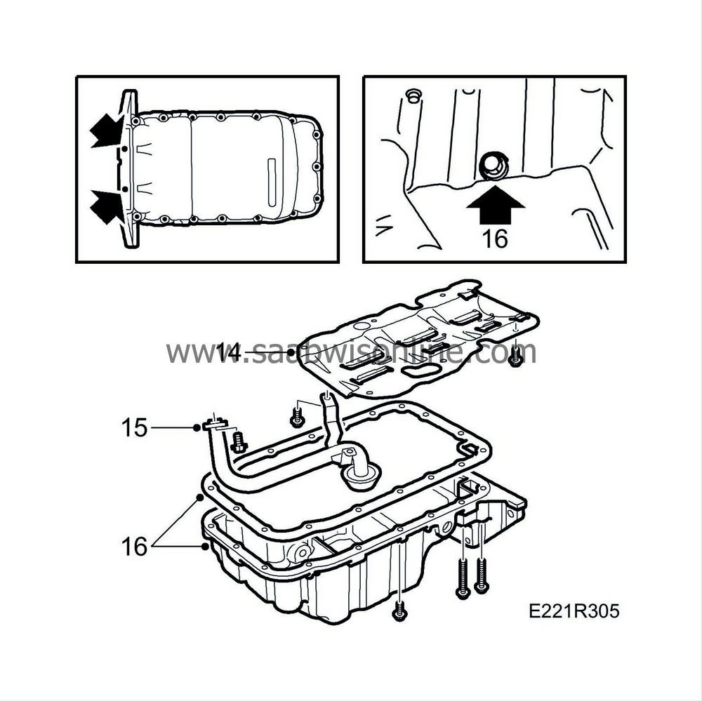
Tightening torque: 8 Nm (6 lbf ft) |
|
| 15. |
Fit the oil suction pipe complete with O-ring. Lock the bolts with part No. (10) 74 96 268.
Tightening torque: 8 Nm (6 lbf ft) |
|
| 16. |
Fit the oil sump with a new gasket. Secure the bolts with part No. (10) 74 96 268. Check that the drain plug is tightened firmly.
Tightening torque: Oil sump: 15 Nm (11 lbf ft) Drain plug 25 Nm (18.5 lbf ft) |
|
| 17. |
Turn over the engine. Clean the heat exchanger cover with benzine. Apply
87 81 841 Silicone flange sealant
to the sealing surfaces. Fit the heat exchanger with new O-rings. Tighten the cover.
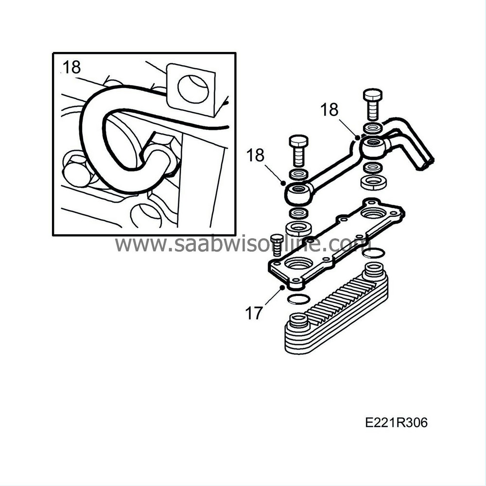
Tightening torque: 20 Nm (15 lbf ft) |
|
| 18. |
Connect the oil pipes to the heat exchanger using new seals. Tighten the connections.
Tightening torque: 30 Nm (22 lbf ft). |
|
| 20. |
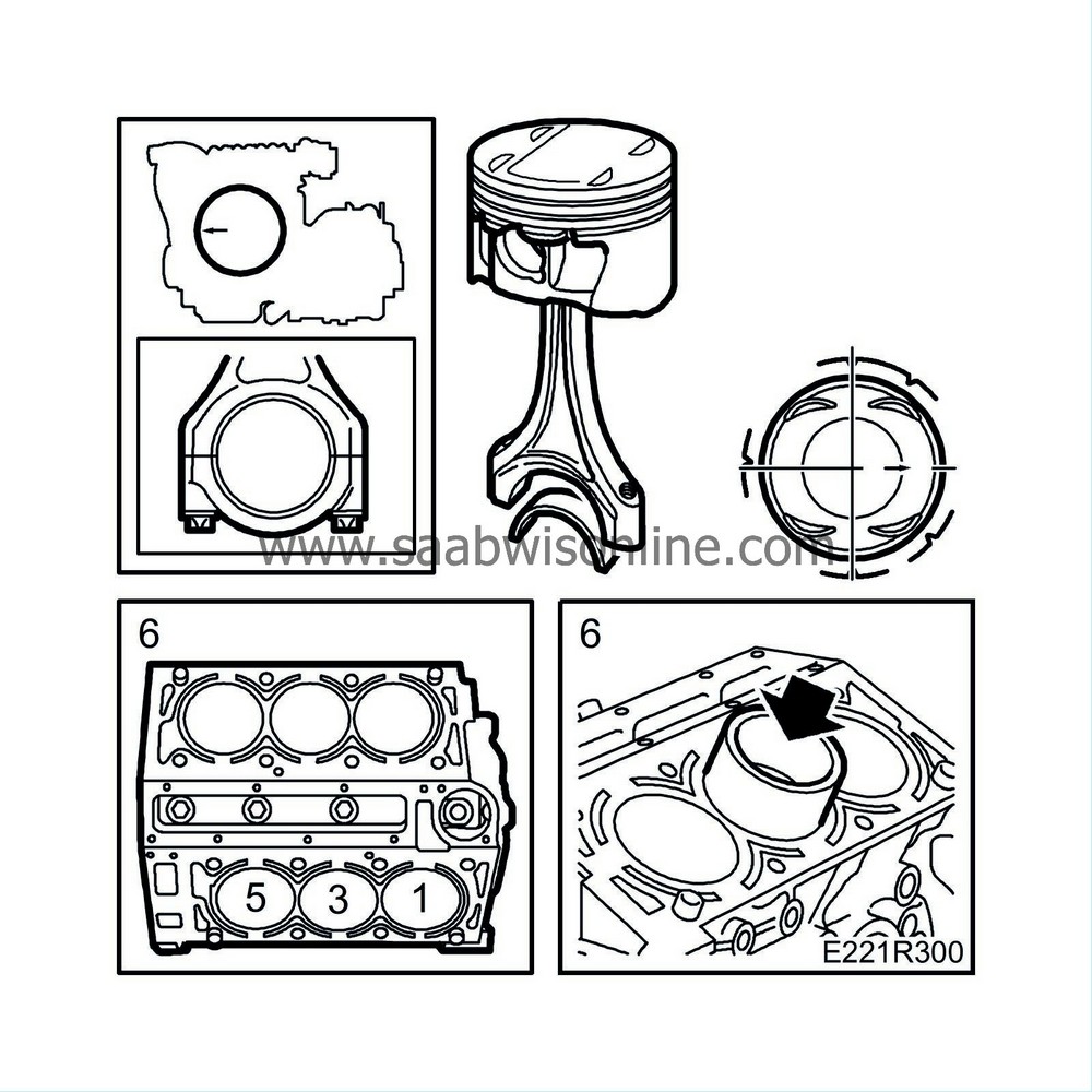
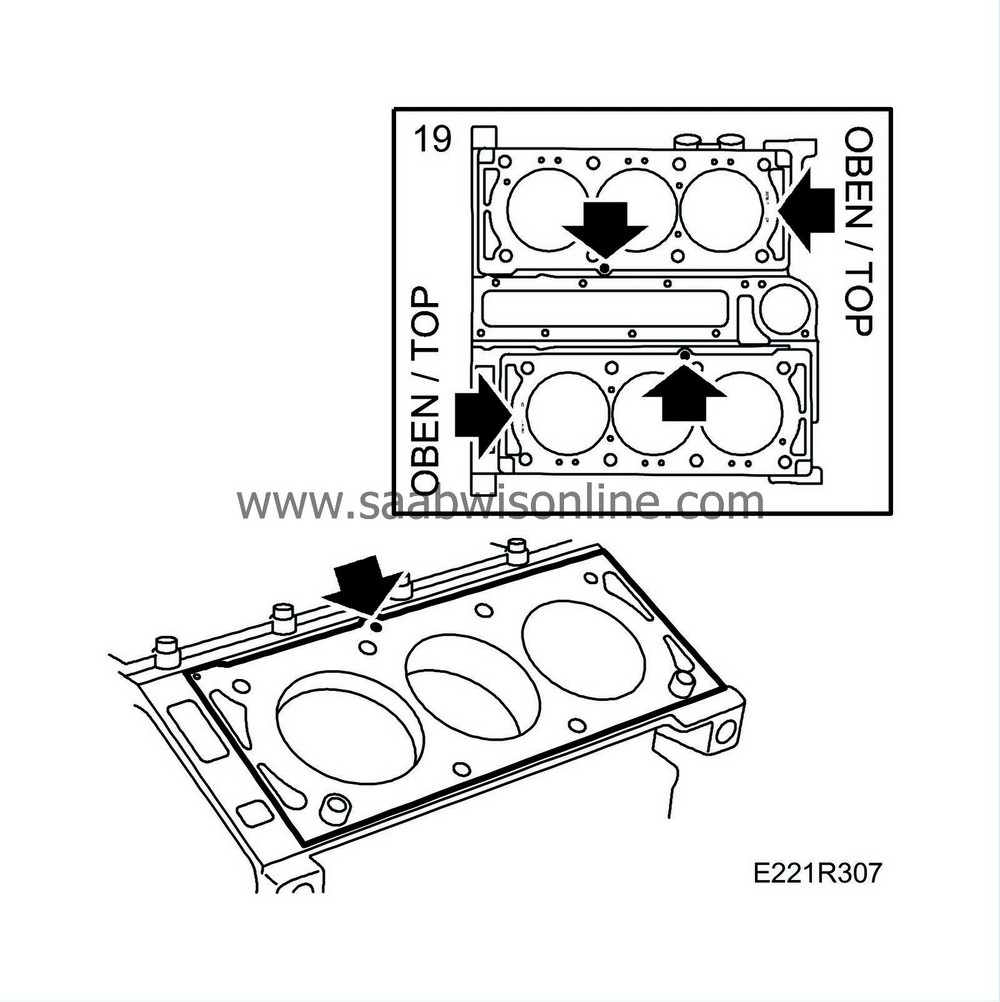
Rotate the crankshaft to 60° BTDC. Fit the cylinder heads with new bolts. Tighten the bolts in the order shown in the illustration.
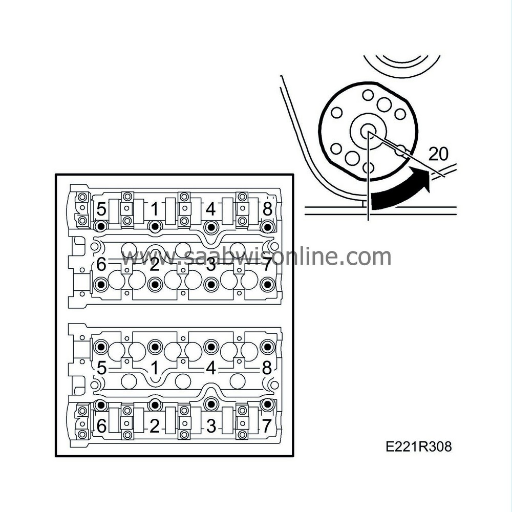
Tightening torque: 25 Nm (18.5 lbf ft) + 90° + 90° + 90° |
|
| 21. |
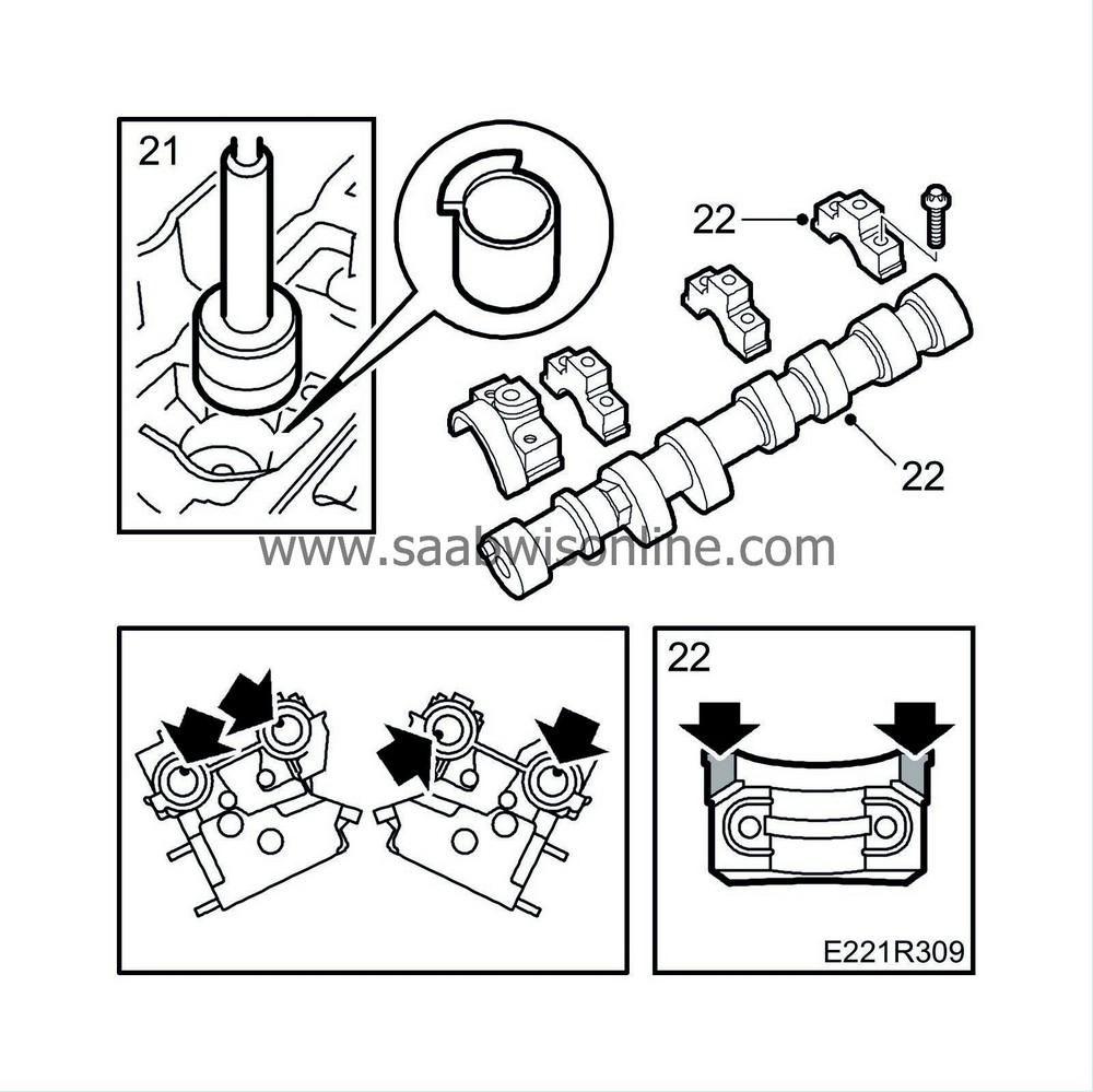
Remove the protective sleeves and fit the valve tappets.
|
|
| 22. |
Place the camshafts in position and fit the stuffing boxes and bearing caps. Start where the cams point downwards and load the tappets. Coat the cylinder head contact surfaces of the front bearing caps sparingly with part No. (10) 74 96 268, see illustration.
Cylinders 1-3-5 (rear) The locating pin on the camshafts should point towards the inside bolts for the camshaft bearing caps. Cylinders 2-4-6 (front) The locating pin for the intake camshaft should be in line (downwards) with the inside bolts for the camshaft bearing caps. The guide pin for the exhaust camshaft should point straight up from the plane of the cylinder head. Tightening torque: 8 Nm (6 lbf ft)
|
|||||||||||||
| 23. |
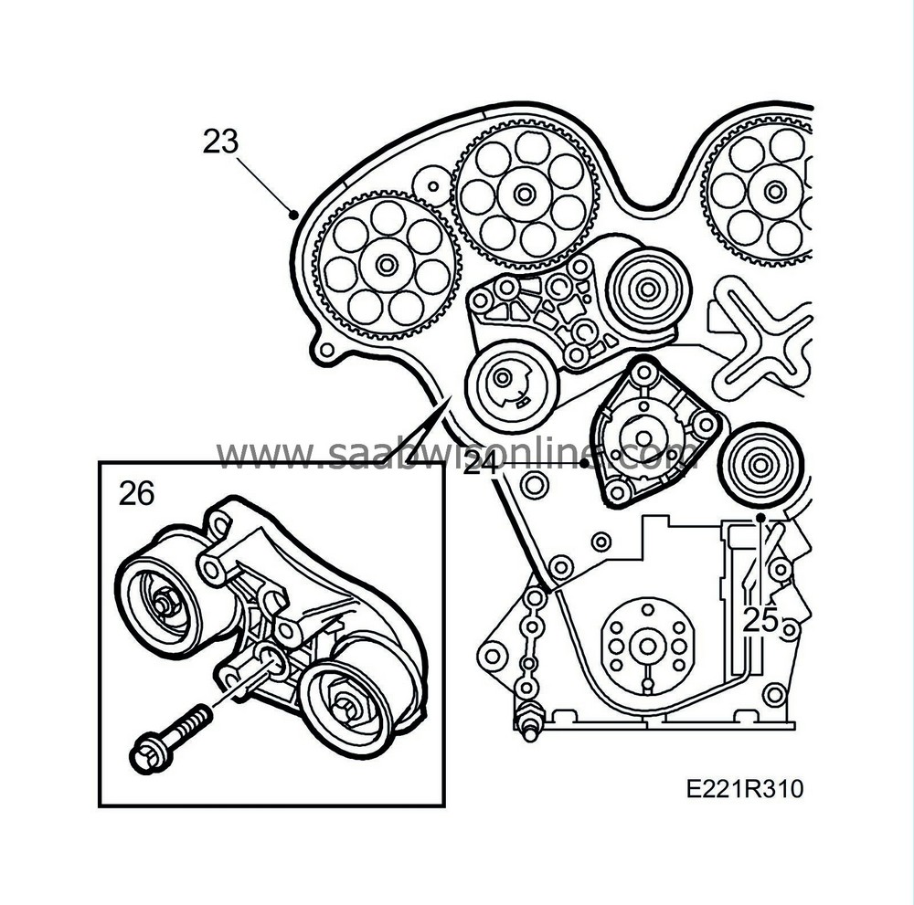
Fit the inner (rear) timing cover.
|
|
| 24. |
Fit the coolant pump with a new O-ring. Coat the O-ring and sealing surface on the cylinder block with non-acidic vaseline.
Tightening torque: 25 Nm (18.5 lbf ft). |
|
| 25. |
Fit the new adjuster roller.
Tightening torque: 40 Nm (30 lbf ft) |
|
| 26. |
Fit the bracket with tensioning roller and the upper adjuster roller.
|
|
| 28. |
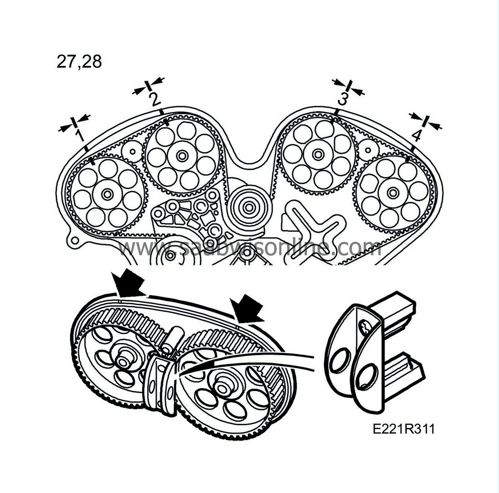
Carefully turn the camshafts so that the markings on the camshaft sprockets are aligned with the grooves on the inner (rear) timing cover. Use KM-800-20. Lock the camshafts with KM-800-1 (cylinders 1-3-5) and KM-800-2 (cylinders 2-4-6).
|
|
| 29. |
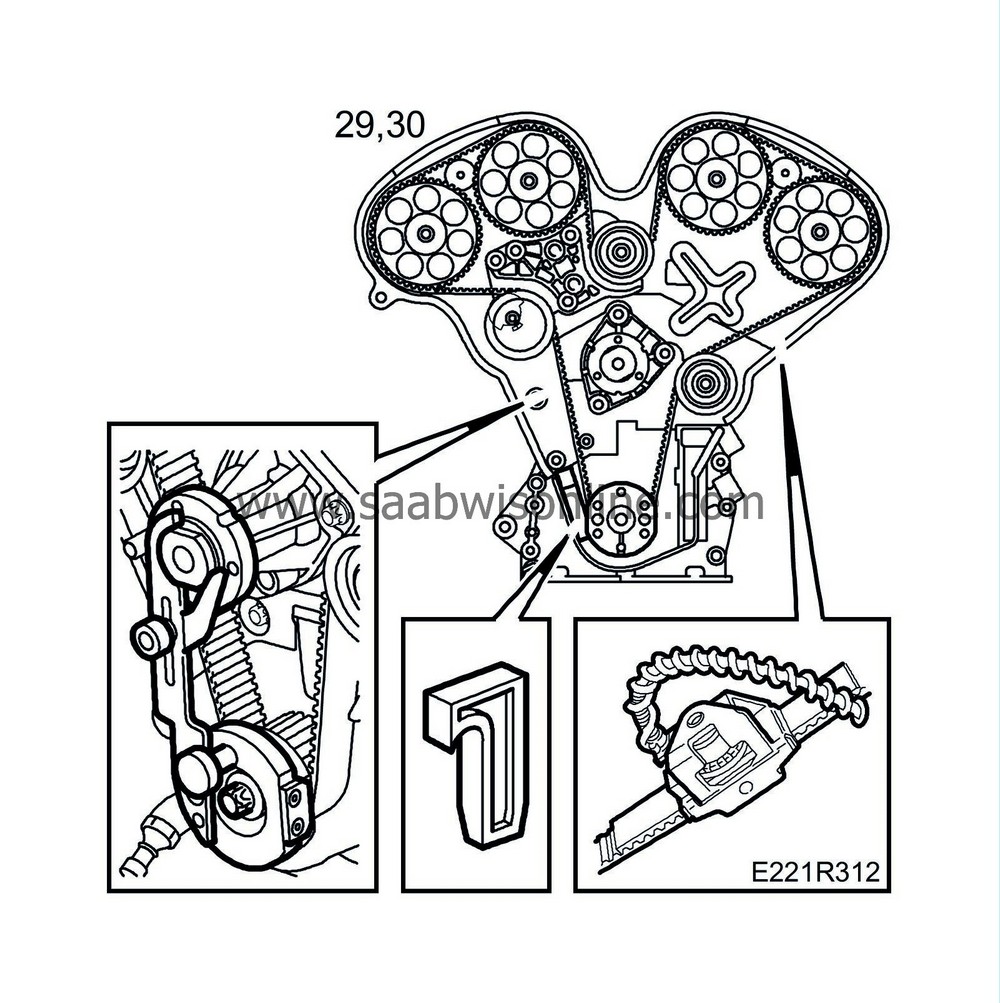
Turn the crankshaft in the direction of rotation of the engine until just before TDC. Fit KM-800-10 on the crankshaft and turn the crankshaft to TDC. Press the movable arm against the flat part of the coolant pump flange and attach it.
|
|
| 30. |
1. Put on the camshaft belt according to the markings on the belt and the marked direction of rotation. Use
83 95 006 Adjustment tools, cam sprockets and timing belt, V6
KM-800-30 to keep the belt in place. Fit the lower tensioning pulley loosely. Make sure the washer is in place. Adjust the tensioning pulley by hand so that the belt does not jump. Adjust anti-clockwise. Make sure the markings on the timing belt and the corresponding markings on the cam sprocket and crankshaft are aligned. Remove the tool KM-800-30.
Fit locking tool KM-800-10, position a piece of camshaft belt and fit part no. 83 93 985 to measure the belt tension. Tighten the centre bolts of the adjuster rollers lightly. Adjust the lower adjuster roller anticlockwise until a tension of 275-300 Nm is obtained. Use tool 83 94 983. Tighten the adjuster roller's bolt. Use tool 83 94 983 as a counterstay. Check the belt tension again and adjust as necessary. Tightening torque: 40 Nm (30 lbf ft)
|
||||||||||
| 31. |
Ensure the adjusting nut on the upper adjusting roller rotates freely and is not tight. Adjust the tensioning pulley with a 5 mm Allen key until the two lines on the tensioning pulley correspond with each other. Tighten.
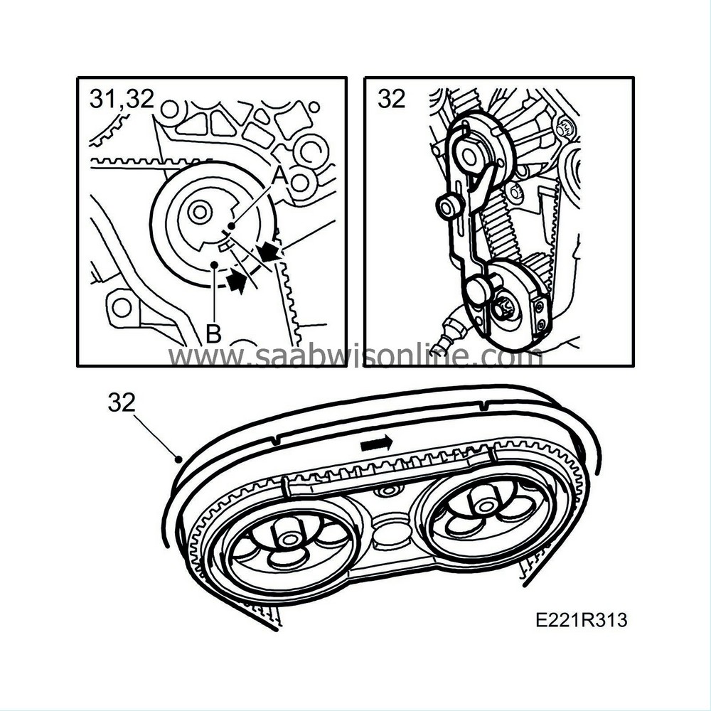
Tightening torque: 20 Nm (15 lbf ft) Remove the locking tool for camshaft sprockets 1 and 2. Fit tool KM-800-20. Then, adjust the upper adjusting roller anticlockwise with tool 83 94 983 until the markings on the camshaft sprocket are aligned with the corresponding markings on KM-800-20. Tighten. Use tool 83 94 983 as a counterstay. Tightening torque: 40 Nm (30 lbf ft)Remove KM-800-20 and the other locking tools. |
|
| 32. |
Rotate the engine two revolutions in the direction of rotation until just before the zero mark and fit locking tool KM-800-10 on the crankshaft. Carefully rotate the crankshaft in the direction of rotation of the engine until the arm is lying against the coolant pump and tighten it. Fit tool KM-800-20 and ensure the markings on the camshaft sprocket are opposite the markings on the tool and that the edge of the belt is aligned with the edge of the sprocket.
|
||||||||||
| 33. |
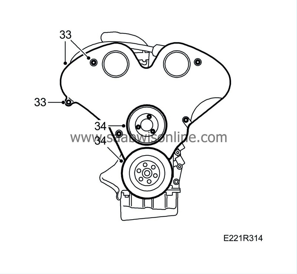
Fit the timing cover.
|
|
| 34. |
Fit the coolant pump pulley and crankshaft pulley.
Tightening torque: Belt pulley/coolant pump: 8 Nm (6 lbf ft) Belt pulley/crankshaft: 20 Nm (15 lbf ft) |
|
| 35. |
Fit new gaskets on the camshaft covers and wipe clean. Lubricate with a soap solution and place part No. (10) 81 52 381 in the corners at the camshaft bearing caps. Fit the camshaft covers.
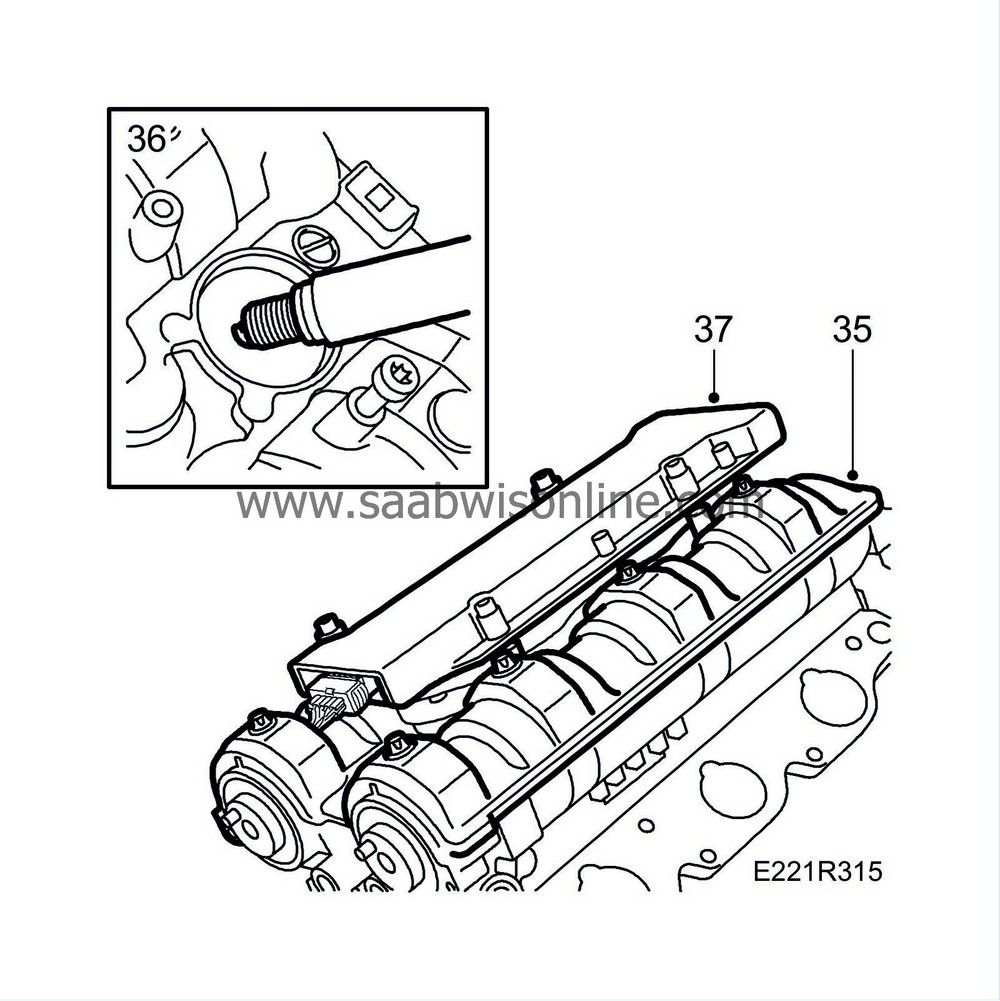
Tightening torque: 8 Nm (6 lbf ft) |
|
| 36. |
Fit the spark plugs using spark plug socket 83 95 485.
Tightening torque: 25 Nm (18.5 lbf ft). |
|
| 37. |
Fit the ignition discharge modules. Connect the cables to the ignition discharge modules and fit the engine wiring harness.
|
|
| 38. |
Fit the crankcase breather housing.
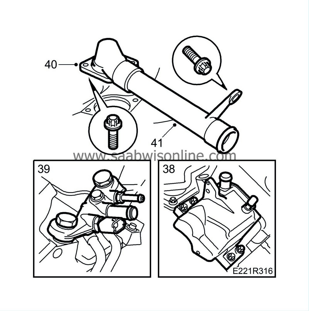
|
|
| 39. |
Fit the coolant bridge with new copper gaskets. Coat the bolts with part No. (10) 74 96 284.
Tightening torque: 30 Nm (22 lbf ft). |
|
| 40. |
Fit the thermostat with a new O-ring. Moisten the O-ring with coolant.
Tightening torque: 20 Nm (15 lbf ft) |
|
| 41. |
Refit the coolant pipe with new O-rings. This will be easier if the O-rings are moistened with coolant.
|
|
| 42. |
Fit the lower intake manifold with new gaskets.
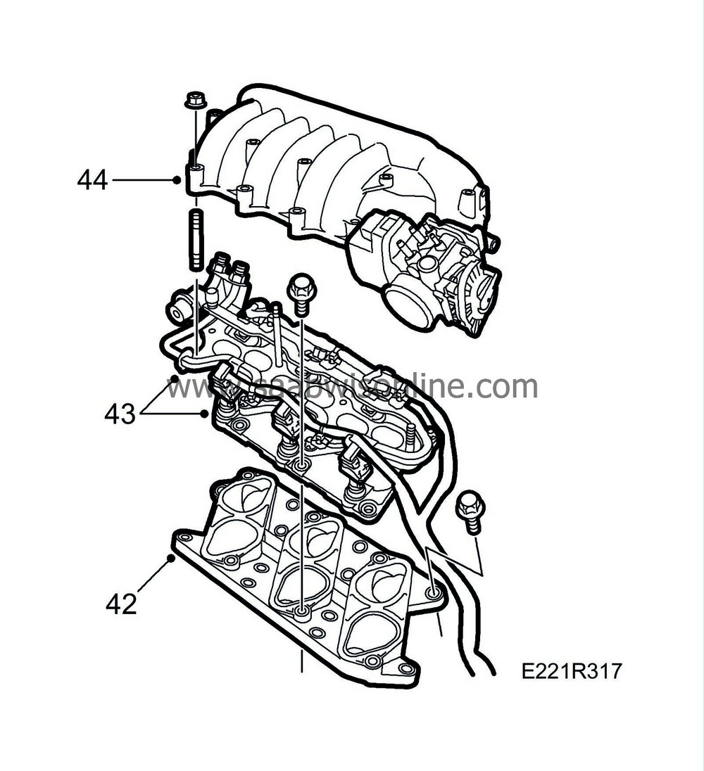
Tightening torque: 20 Nm (15 lbf ft) |
|
| 43. |
Fit the middle intake manifold. Connect the cables to the injectors.
Tightening torque: 20 Nm (15 lbf ft) |
|
| 44. |
Fit the upper intake manifold with a new gasket.
Tightening torque: 20 Nm (15 lbf ft) |
|
| 45. |
Fit the front exhaust manifold with a new gasket. Clean the sealing surfaces before fitting.
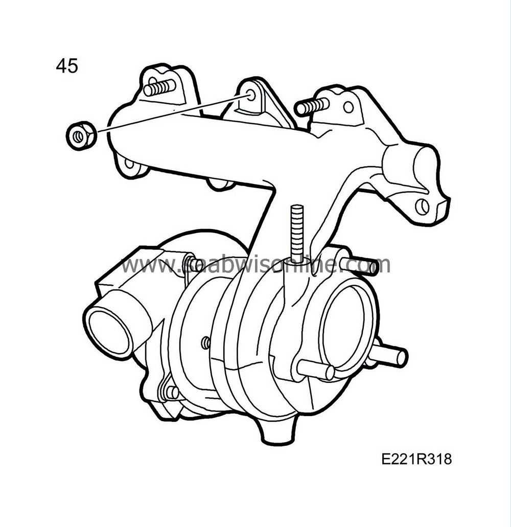
Tightening torque: 20 Nm (15 lbf ft)
|
|||||||
| 46. |
Fit the rear exhaust manifold with a new gasket. Fit the heat shield over the rear exhaust manifold.
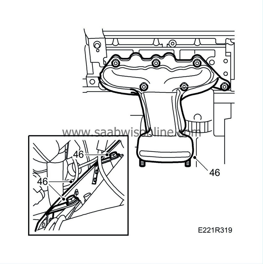
|
|
| 47. |
Fit the oil filter and connect the oil filter adapter's oil pipes.
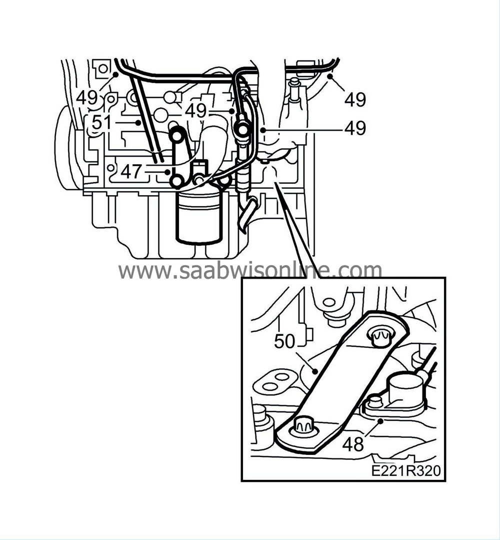
Tightening torque: Oil filter 10 Nm (7.5 lbf ft) Oil pipe 25 Nm (18.5 lbf ft) |
|
| 48. |
Fit the crankshaft position sensor with a new O-ring.
Tightening torque: 8 Nm (6 lbf ft) |
|
| 49. |
Connect the turbo's water and oil pipes.
Tightening torque: Oil return pipe, M6 bolt: 14 Nm (10 lbf ft) Oil pipe, turbo: 20 Nm (15 lbf ft) Oil pipe, oil filter adapter: 20 Nm (15 lbf ft) Water pipe: 25 Nm (18.5 lbf ft) Cylinder head retaining bolt 14 Nm (10 lbf ft)
|
|||||||||||||
| 50. |
Fit the turbo's bracket.
Tightening torque: 24 Nm (18 lbf ft) |
|
| 51. |
Fit the dipstick.
|
|
| 52. |
Connect the cable to the oil pressure sensor.
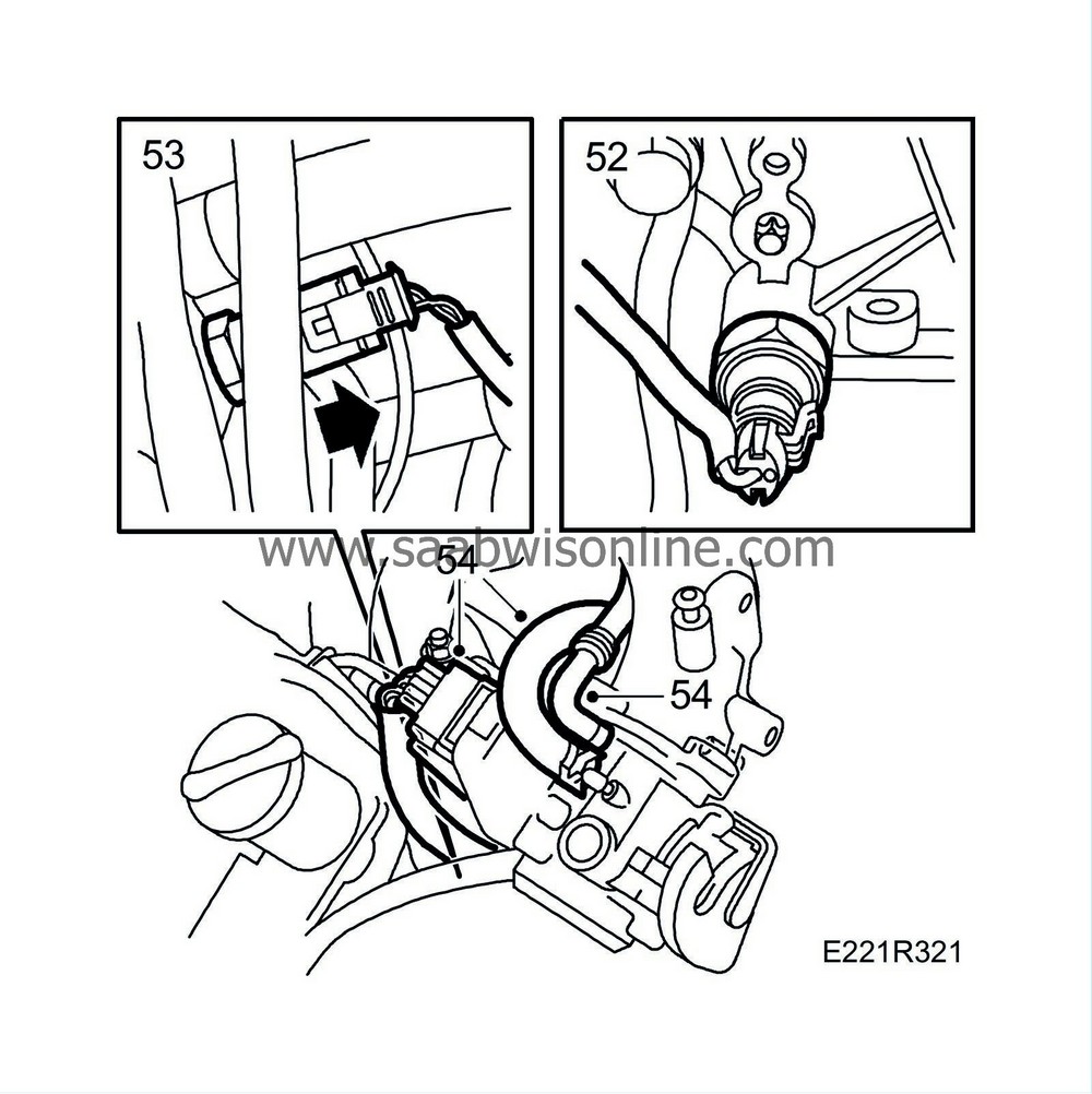
|
|
| 53. |
Connect the temperature sensor to the coolant bridge.
|
|
| 54. |
Connect the vacuum hose and water hose to the throttle. Also plug in the throttle's connector.
|
|
| 55. |
Fit and connect the generator. Connect the cable for the oil pressure sensor to the generator.
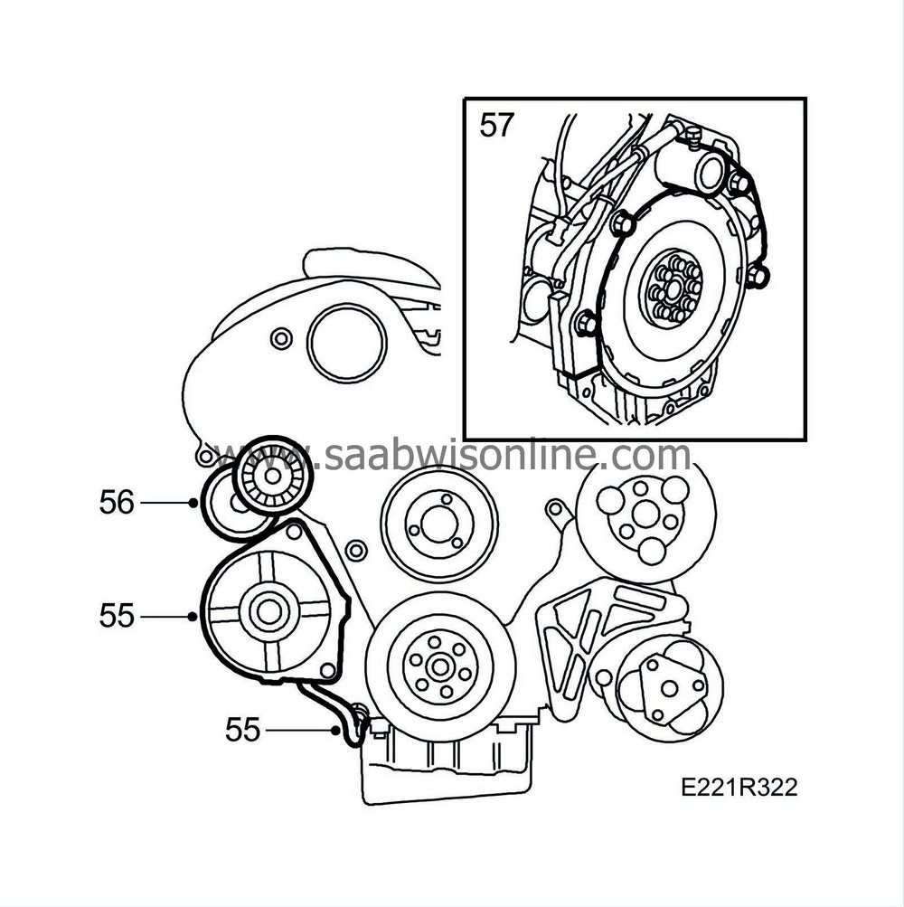
|
|
| 56. |
Fit the belt tensioner.
Tightening torque: 40 Nm (30 lbf ft) |
|
| 57. |
Fit a lifting sling and lift the power unit away from the stand. Remove the holder.
|
|
| 58. |
Position the gearbox and tighten the bolts. Fit the front exhaust pipe with heated oxygen sensor, power steering pump and power unit to the subframe.
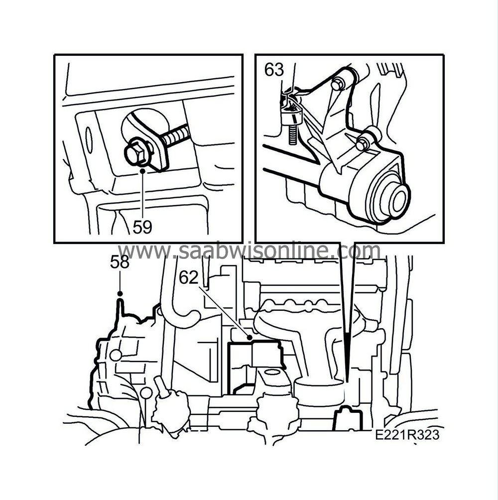
Tightening torque: Gearbox: 70 Nm (52 lbf ft) |
|
| 59. |
Remove the torque converter's fixing tool.
|
|
| 60. |
Bolt the drive plate and torque converter together by gradually rotating the crankshaft so that all the bolts can be tightened.
Turning torque: 60 Nm (44 lbf ft). |
|
| 61. |
Fit the plastic plug under the starter motor.
|
|
| 62. |
Fit the starter motor and connect the cables.
|
|
| 63. |
Fit the support bearing bracket with pipe and inboard drive-shaft universal joint.
|
|
| 64. |
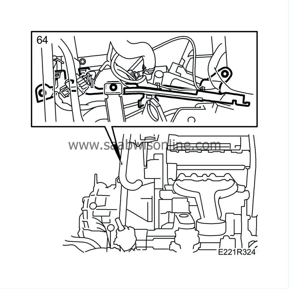
Fit the bracket for the engine wiring harness.
|
|
| 65. |
Fill up with oil.
|
|
The power unit is now ready to be fitted in the car.

 Warning

