Components
| Components |
Fuel pump
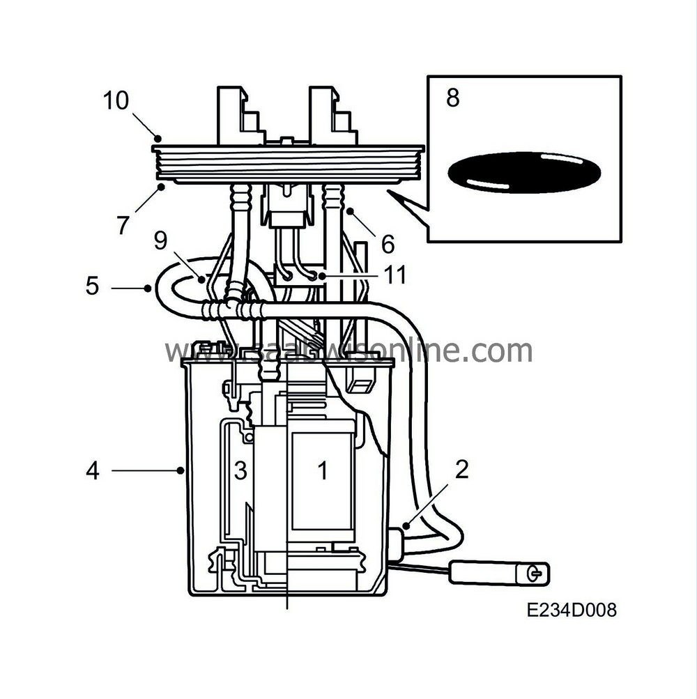
| 1. |
Pump
|
|
| 2. |
Ejector
|
|
| 3. |
Filter
|
|
| 4. |
Reservoir
|
|
| 5. |
Pump delivery line
|
|
| 6. |
Return line
|
|
| 7. |
Pump cover
|
|
| 8. |
O-ring
|
|
| 9. |
Spring element
|
|
| 10. |
Screw ring
|
|
| 11. |
RFI filter
|
|
| Fuel pump |
The fuel pump is situated inside a plastic reservoir clamped between the top and bottom of the tank. It is located by ribs on the bottom of the tank and secured at the top by means of the pump cover (7). The pump is fitted in the tank by screwing the screw ring (10) into the pump cover from outside the tank. Any flexing of the tank is absorbed by the fuel pump's spring element (9).
An ejector is "driven" by the flow of fuel through the delivery line via a T-piece. The pump is an electric rotary pump. The purpose of the ejector is to ensure that the pump is continuously supplied with fuel. Due to the location of the pump in the reservoir, the supply of fuel to the engine is maintained during cornering and acceleration even when there is only a small quantity of fuel left in the tank.
The pump can be removed through a hole under the rear seat cushions.
A non-return valve on the pressure side of the pump, fitted in the connecting nipple on the pump cover, prevents the pressure in the fuel line from dropping immediately after the engine has been switched off. The non-return valve on the return side of the pump prevents fuel from flowing "in reverse" should the car happen to overturn.
The fuel level sensor in the tank is mounted on the fuel pump plastic reservoir via a jointed arm.
The RFI filter helps to reduce the risk of radio interference in the system.
| Fuel filter |

The fuel filter is mounted in the pressure line between the fuel pump and the fuel rail at the front of the fuel tank on the right-hand side.
The purpose of the filter is to remove contaminants and foreign matter from the fuel and so prevent clogging of the injectors.
The filter contains a paper element having a mean porosity of 5 µm and after it a strainer to catch any paper fragments that may have worked loose. A support locates the filter element in the housing, which is made of metal. The efficiency of the filter is dependent on the cleanliness of the fuel.
| Fuel rail, 4 cyl. |

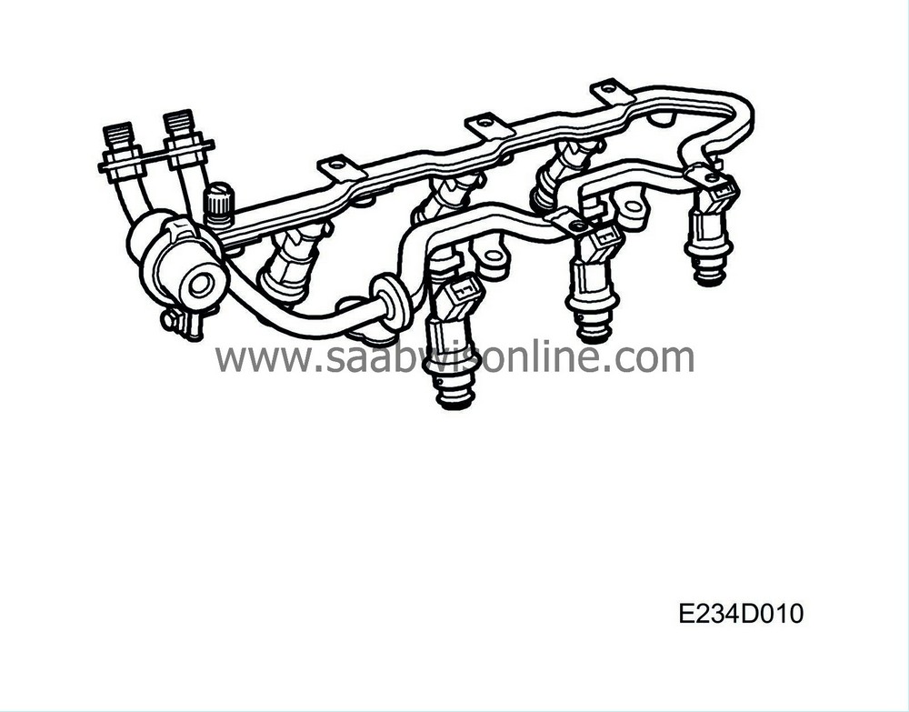
The fuel rail meters equal amounts of fuel to all the injectors. It also acts as a pressure equalizer. In relation to the amount of fuel consumed during each injection, the fuel rail has sufficient capacity to prevent variations in pressure. The design and construction of the fuel rail makes for a simple method of fitting the injectors, which are connected directly to it.
Also connected to the fuel rail are the fuel line and fuel pressure regulator.
| Fuel distribution pipe, V6 |

The fuel rail meters equal amounts of fuel to all the injectors. It also acts as a pressure equalizer. In relation to the amount of fuel consumed during each injection, the fuel rail has sufficient capacity to prevent variations in pressure. The design and construction of the fuel rail makes for a simple method of fitting the injectors, which are connected directly to it.
Also connected to the fuel rail are the fuel line and fuel pressure regulator.
| Injectors, 4 cyl. |

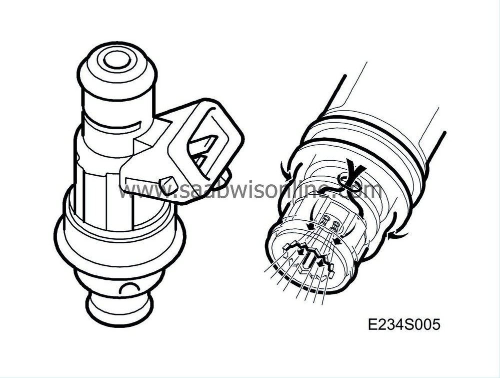
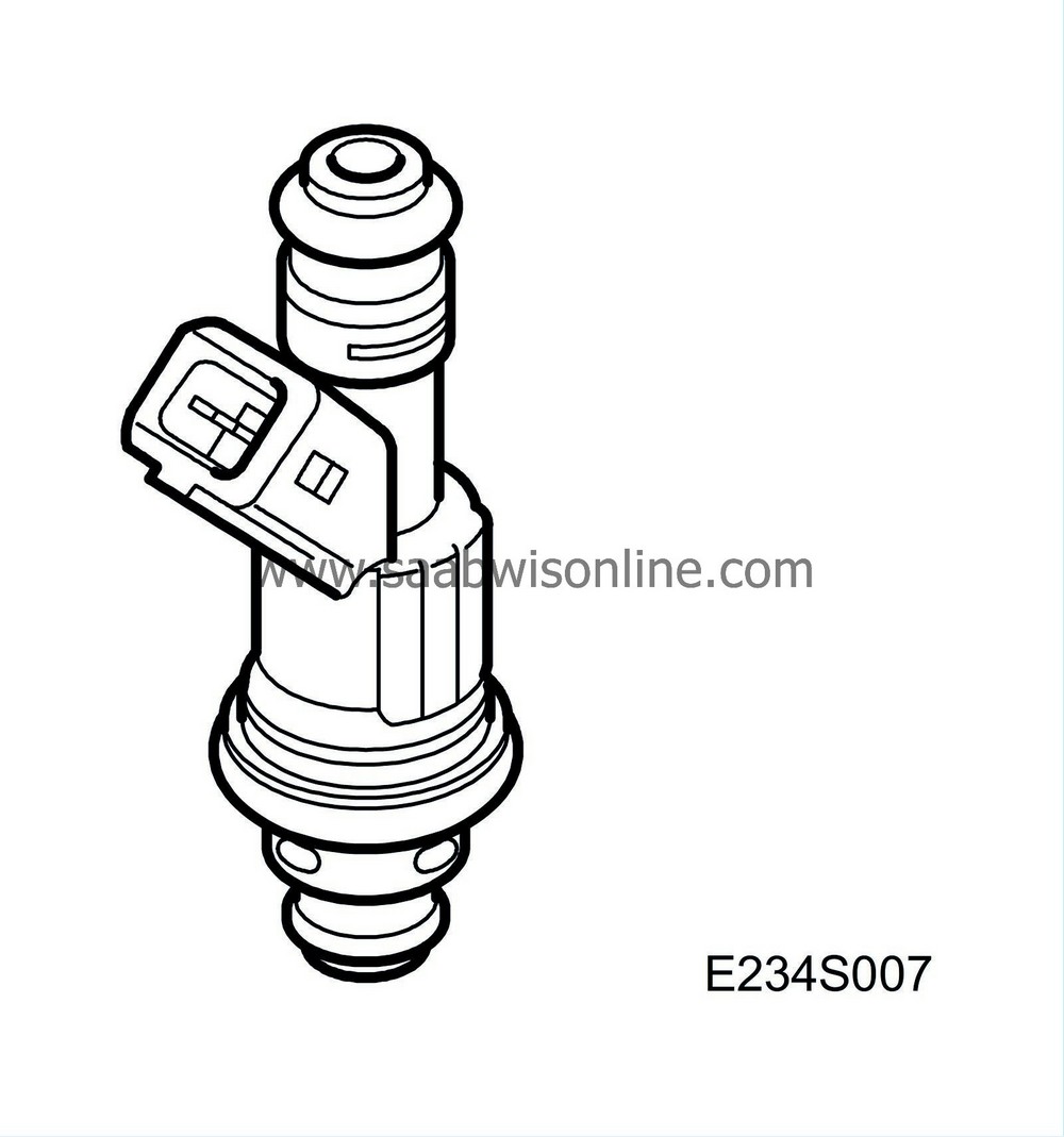
The injectors are connected directly to the fuel rail. They are located in the intake ports in front of the inlet valves.
The injectors consist of a valve body and spray nozzle with electromagnetic armature. The valve body contains a solenoid winding and actuator for the spray nozzle. The injectors are controlled electromagnetically, opening and closing by means of electric pulses from the control module.
The injectors are of the air-cooled type. A separate passage in the intake manifold supplies air to the relevant injector. The air is directed to an annular nozzle situated round the fuel orifices. This system ensures improved atomization of the fuel.
For more information on the injectors, refer to Group 2 “Engine management system, Trionic 4-cyl.”
 .
.
| Injectors, V6 |

The injectors are connected directly to the fuel rail. They are located in the intake ports in front of the inlet valves.
The injectors consist of a valve body and spray nozzle with electromagnetic armature. The valve body contains a solenoid winding and actuator for the spray nozzle. The injectors are controlled electromagnetically, opening and closing by means of electric pulses from the control module.
For more information on the injectors, refer to Group 2 “Engine management system, Trionic V6”
 .
.
| Pressure regulator |

The pressure regulator is mounted on the short side of the fuel rail.
The pressure regulator maintains a constant ratio between the fuel pressure and the pressure in the intake manifold. This ensures that the amount of fuel injected is determined exclusively by the opening duration of the electromagnetic injectors.
The pressure regulator is a diaphragm-controlled overflow valve set for 3.0 bar. The regulator consists of a metal housing divided into two chambers by a press-fitted diaphragm. In one of the chambers a spiral spring presses against the diaphragm while fuel flows through the other chamber.
When the preset pressure is exceeded, a valve controlled by the diaphragm exposes an opening to the return line through which superfluous fuel can flow back to the fuel tank.
The spring-loaded chamber of the pressure regulator is connected by a hose to the engine's intake manifold after the throttle. In consequence, the pressure in the fuel system is affected by the absolute pressure in the intake manifold, with the result that the pressure drop across the injectors is constant at all intake manifold pressures.


