Checking and adjusting basic charging pressure
| Checking and adjusting basic charging pressure |
| 1. |
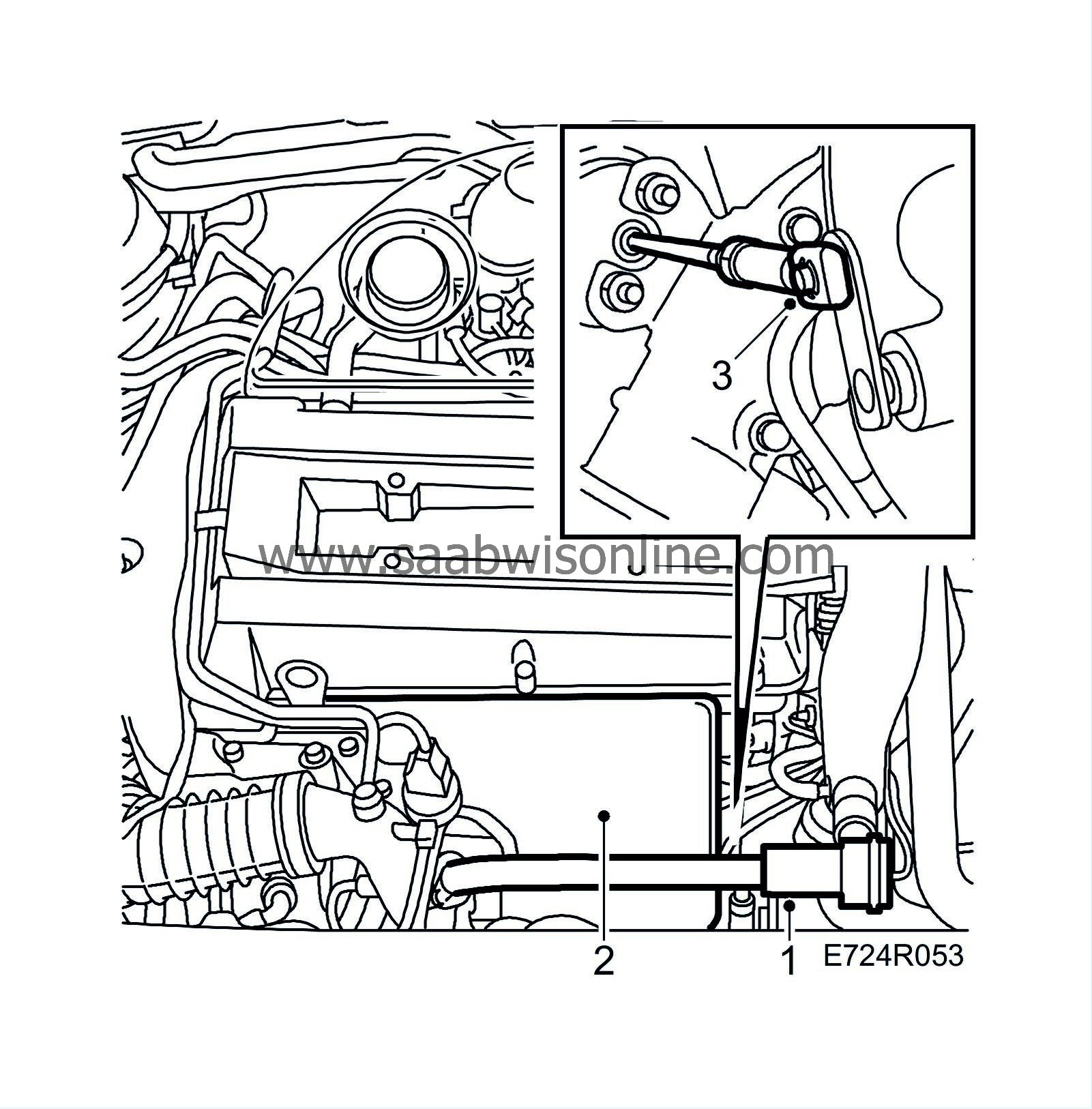
Remove the bypass pipe with valve.
|
|||||||
| 2. |
Remove the exhaust manifold's heat shield.
|
|
| 3. |
Remove the operating arm's locking clip using the special tool (part no. 83 94 538).
|
|
| 4. |
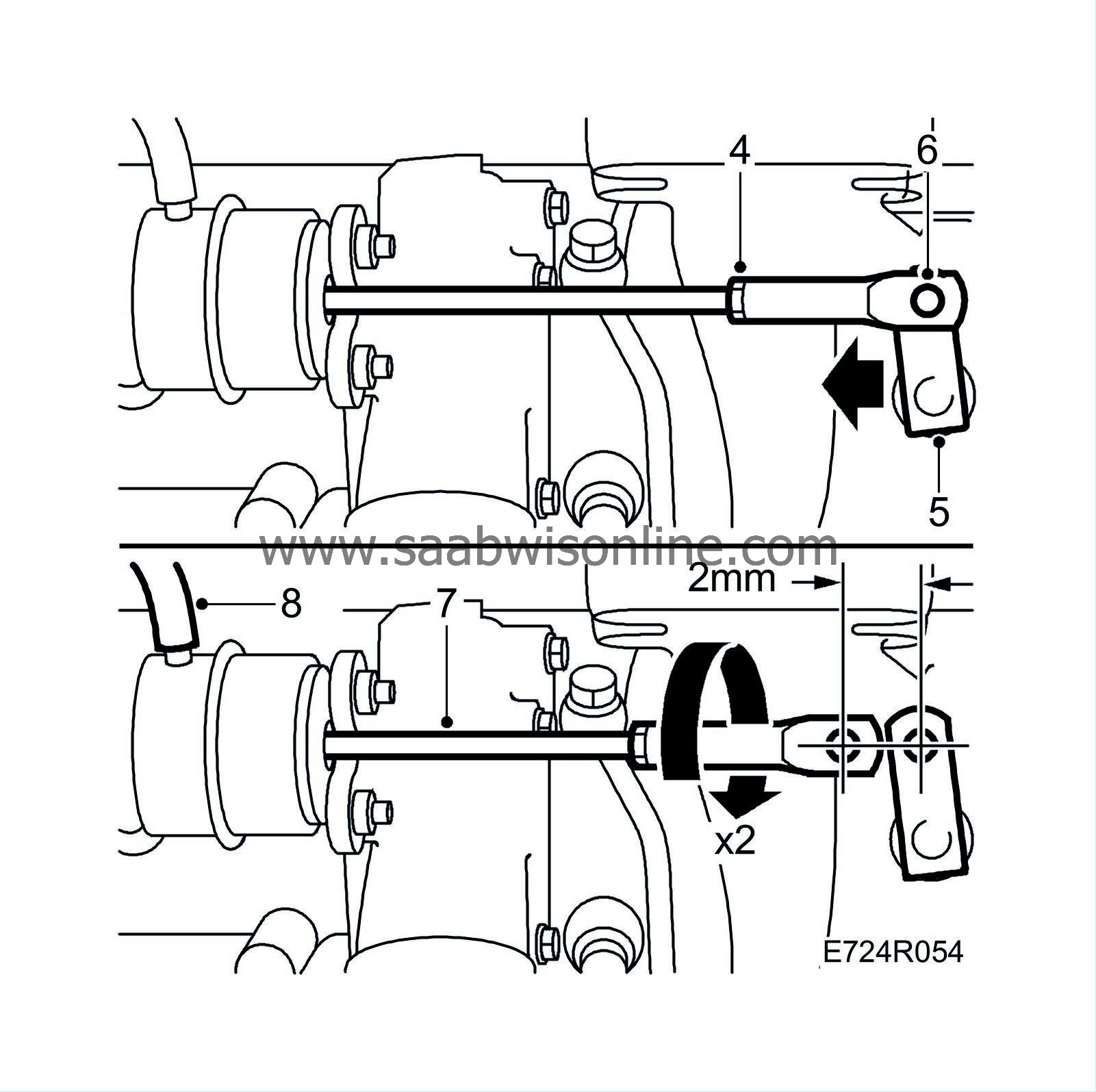
Grip the pushrod with pliers (part no. 83 94 066) or similar tool and undo the locknut with special tool (part no. 83 94 520) or similar tool.
|
|
| 5. |
Hold the operating arm and remove the pushrod from it. Secure the operating arm as it might otherwise “overcentre”.
|
|
| 6. |
Move the operating arm on the charge pressure control valve to the “Closed” position and adjust the end piece so that the pushrod can easily be fitted on the operating arm's pin.
|
|
| 7. |
Detach the pushrod from the operating arm's pin. Turn the end piece clockwise about 2 turns so that a prestress of 2 mm is obtained. Attach the pushrod to the operating arm's pin. Fit the circlip.
|
|
| 8. |
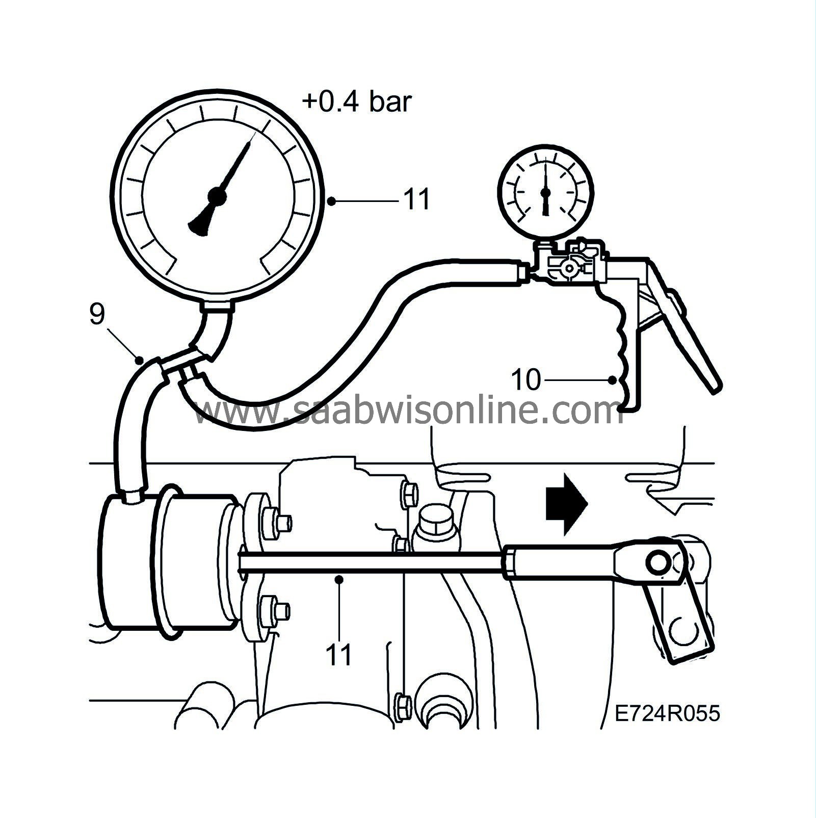
Detach the hose marked “W” from the diaphragm unit.
|
|
| 9. |
Connect the pressure/vacuum pump, part no. 30 14 883, to the diaphragm unit and the pressure gauge using the special tool (part no. 83 93 514).
|
|
| 10. |
Carefully pump up the pressure so that the control rod moves and regulates the charge pressure.
|
|
| 11. |
Read the pressure indicated on the gauge scale just as the control rod starts to move. It should be at least 0.4 bar (but not abnormally high).
|
|
| 12. |
If the pressure is too low, shorten the rod additionally until 0.4 bar is obtained.
|
|
| 13. |
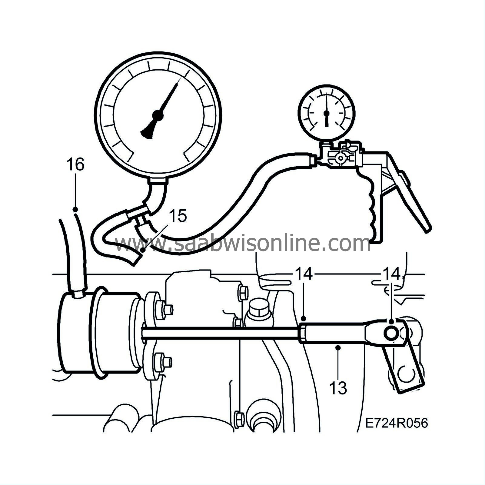
Undo the pushrod and apply a thin coat of Molykote 1000 (part no. 30 20 971) or equivalent to the pin on the operating arm.
|
|
| 14. |
Fit the pushrod and clip, grip the pushrod and lock the nut.
|
|
| 15. |
Disconnect the pressure gauge and pump.
|
|
| 16. |
Reconnect the hose to the diaphragm unit.
|
|
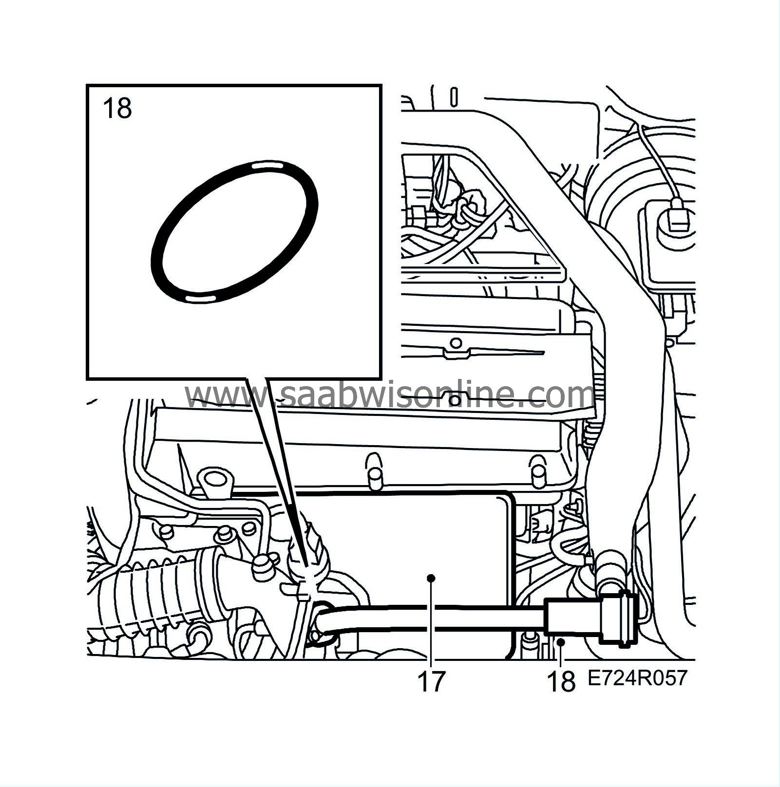
| 17. |
Fit the heat shield, coat its stud with Molykote 1000 (part no. 30 06 665) or the equivalent and screw on the nut.
|
|
| 18. |
Lubricate the O-ring with non-acidic vaseline and fit the bypass pipe.
Tightening torque 8 Nm (5.9 lbf ft) |
|


