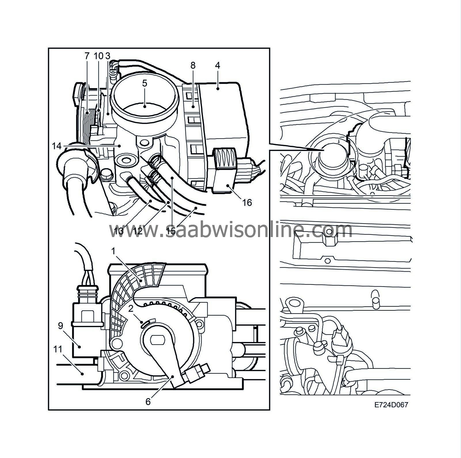
Throttle control
| Throttle control |
| 1. |
Pedal arm with mounting for accelerator cable (rotates pedal position sensors).
|
|
| 2. |
Return spring on pedal arm (not visible, located behind the pedal arm).
|
|
| 3. |
Pedal position sensors (2 potentiometers)
|
|
| 4. |
Motor (brushless DC motor, rotates throttle spindle and disc, throttle position sensor and throttle arm).
|
|
| 5. |
Throttle
|
|
| 6. |
Throttle arm
|
|
| 7. |
Throttle arm return spring
|
|
| 8. |
Throttle position sensors (2 potentiometers)
|
|
| 9. |
Limp-home solenoid (activated 5 times in succession on limp-home and each time the ignition is turned on if a diagnostic trouble code that puts the throttle into limp-home mode is stored in the control module memory. If the throttle is put into limp-home mode, the toothed disc will be disengaged).
|
|
| 10. |
Toothed disc (spring loaded by the throttle arm return spring and released by the limp-home solenoid when the throttle goes into limp-home mode. The disc must be reset manually after repair and deletion of the diagnostic trouble code).
|
|
| 11. |
Air after throttle (nipple for purging the EVAP canister).
|
|
| 12. |
Air after throttle (nipple for connecting crankcase ventilation).
|
|
| 13. |
Air before throttle (nipple for connecting to control valve for the turbocharger bypass valve).
|
|
| 14. |
Bypass passage (leads air past the throttle to a passage in the intake manifold that supplies the air for flushing the injectors).
|
|
| 15. |
Pre-heating (2 nipples for coolant circulation to reduce risk of ice forming).
|
|
| 16. |
10-pin connector (2 for motor, 2 for 5V, 2 for ground, 2 for pedal sensor outputs and 2 for throttle position sensor outputs).
|
|
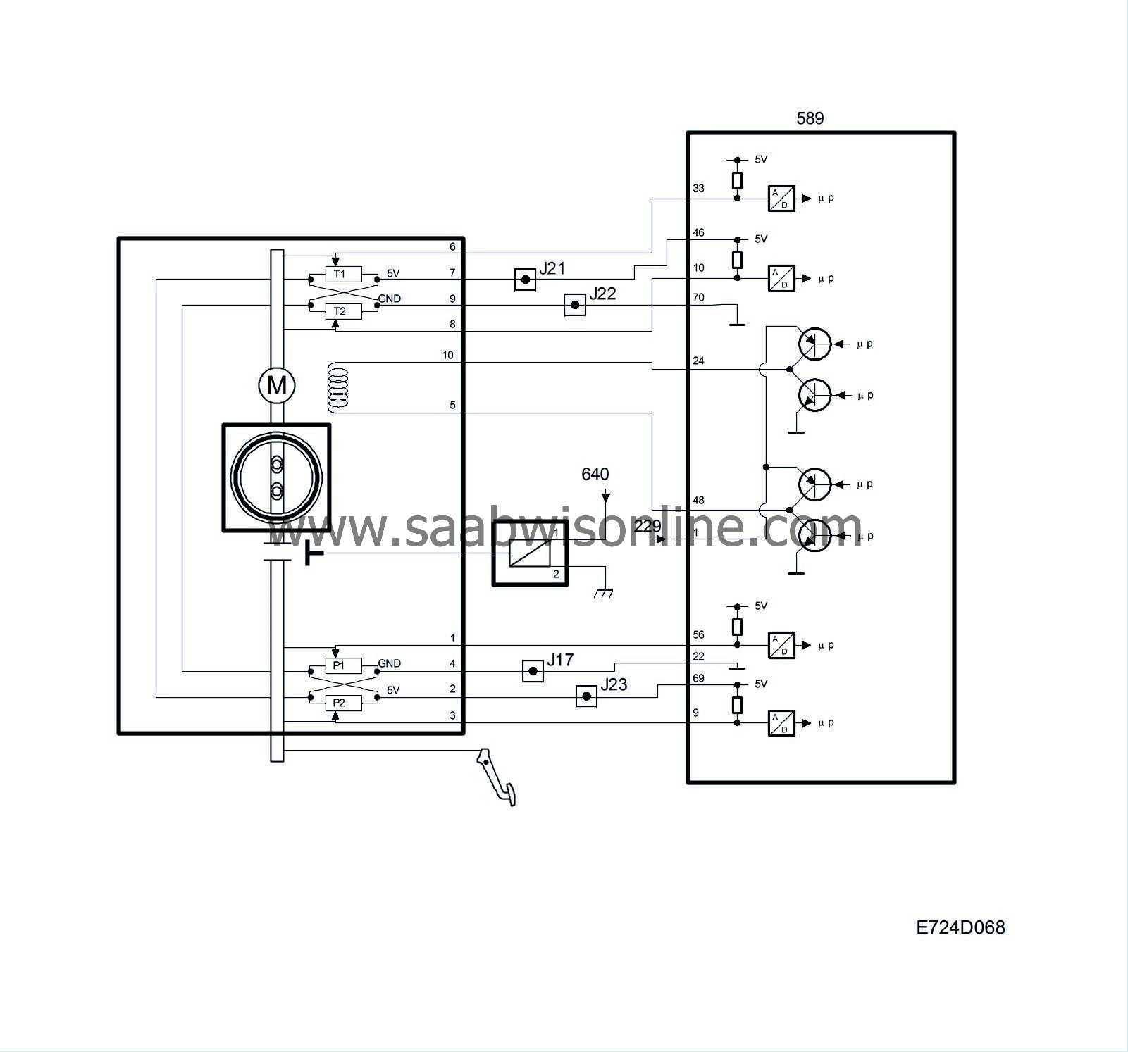
The throttle valve is rotated by a brushless throttle motor powered from control module pins 24 and 48 with 600 Hz PWM. The control module can rotate the throttle in both directions by reversing the polarity of the motor. The PWM ratio increases the further the throttle is from its desired value.
There are two throttle position sensors connected to the throttle spindle. The sensors are two potentiometers powered with 5V from control module pins 46 and 69, which are coupled together in the throttle body, and grounded from control module pins 22 and 70, which are also coupled together in the throttle body.
The voltage from sensor 1 is connected to control module pin 33 and increases with the throttle position. The voltage from sensor 2 is connected to control module pin 10 and decreases with the throttle position. The sum of the two sensor voltages is always 5V.
The voltage from sensor 1 is used by the control module as a value for the current throttle position.
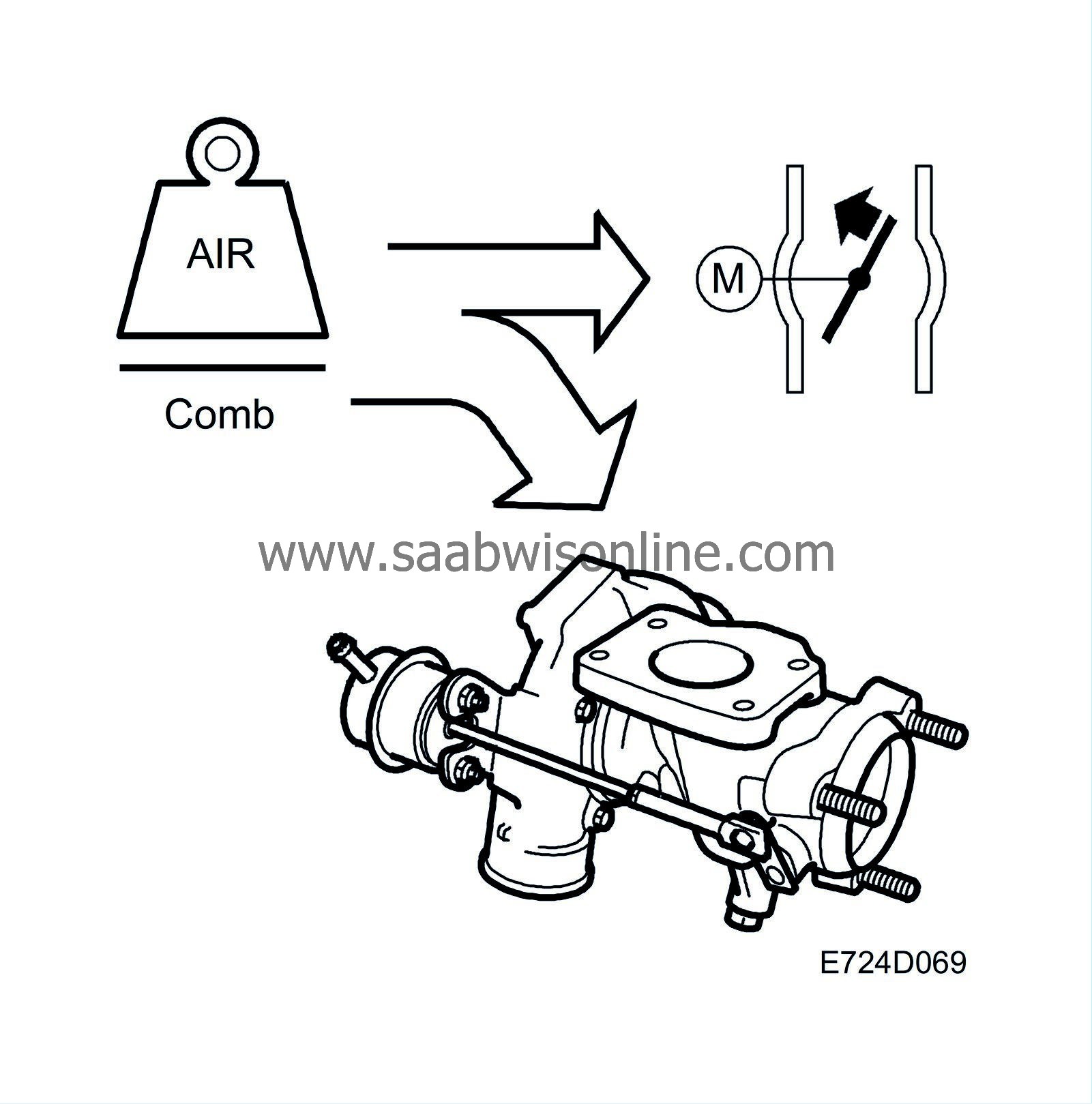
Air mass control requests a certain air mass/combustion. Throttle control converts this value to a requested value for throttle position sensor 1 and compares it with the current value for the sensor.
The difference gives rise to a throttle motor PWM with a polarity that rotates the throttle until the current value corresponds with the requested.
If a major fault should occur in the throttle control, the control module will ground pin 36 and the limp-home solenoid will operate. The solenoid, which is located on the throttle body, then connects the pedal cable to the throttle spindle. The throttle motor is de-energized and the throttle is then controlled directly from the accelerator pedal.
The limp-home solenoid is active for 1 s at first and then for 4 x 0.5 s.
| Note | ||
|
The solenoid must be energized for short periods only, as it is very low-ohmic. |
When the total air mass/combustion requested by the system has been calculated, it must be realized first by the throttle and then, if necessary, by the turbo control.
The requested air mass/combustion is corrected with the air density in front of the throttle. Thinner air requires a greater throttle angle to obtain the same air mass/combustion. The density is calculated using the charge air pressure and the temperature of the intake air.
The value is then converted to requested voltage for throttle position sensor 1. The throttle motor rotates the throttle so that the current sensor voltage corresponds with the requested.
The control module then checks whether the current air mass/combustion corresponds with the requested. If necessary, the throttle position is finely adjusted.
If the requested air mass/combustion is too high to be handled by the throttle control alone, the excess will be taken over by the turbo control.
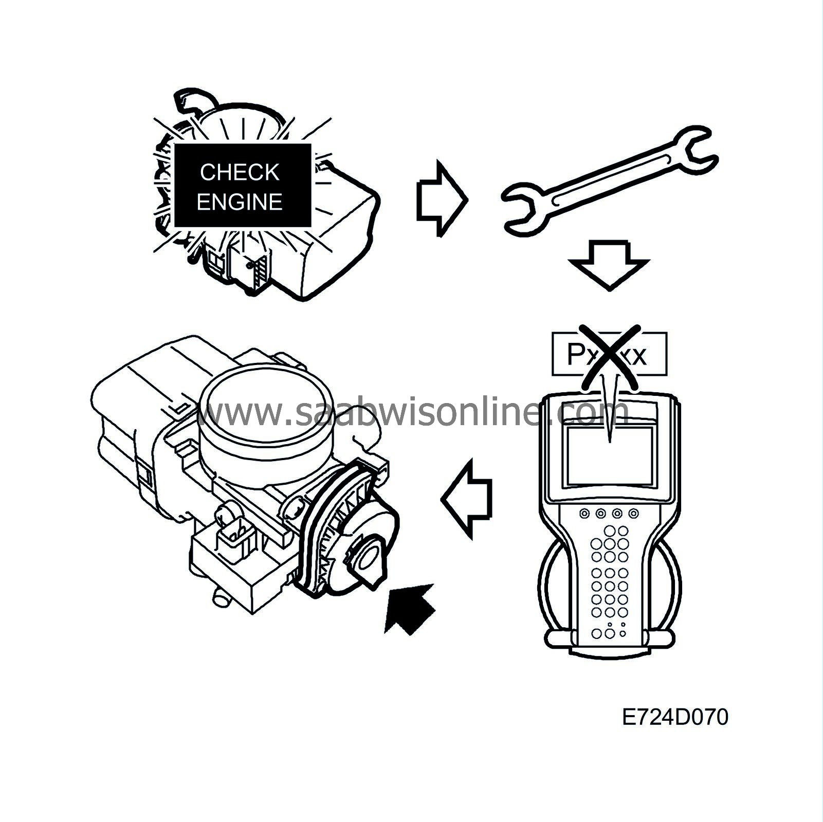
If a safety-related fault should occur in the throttle control, it will go into limp-home mode. The CHECK-ENGINE lamp will go on immediately and the diagnostic trouble code will have to be cleared with the diagnostic tool.
| Diagnostics |
| • |
If the sum of the throttle position sensor voltages differs too widely from 5 V, diagnostic trouble code P1230 will be generated.
|
|
| • |
If a throttle motor fault or a mechanical fault should occur, diagnostic trouble codes P1240, P1251-P1253, P1260-P1261, P1263 or P1264 will be generated.
|
|
| • |
If an internal control module fault that affects the throttle control should occur, diagnostic trouble codes P1601-P1611, P1613-P1614 or P1621 will be generated.
|
|
| • |
If there is an open circuit or short circuit on the control module output to the limp-home solenoid relay, diagnostic trouble code P1670-P1671 will be generated.
|
|
Most of the above faults will put the throttle control into limp-home mode.
| Important | ||
|
When the throttle control system is in limp-home mode, the fault is stored in the control module memory. Each time the ignition is switched on, the limp-home solenoid is activated for 1 s and then for 4 x 0.5 s to ensure that the mechanism is not reset before the fault has been rectified. Repair work must therefore be carried out in the following order: |
||
| 1. |
Rectify the fault.
|
|
| 2. |
Delete the DTCs.
|
|
| 3. |
Reset the limp-home mechanism.
|
|
|
If this sequence is not followed, it is highly likely that the car will leave the workshop with the throttle control system still in limp-home mode. When the system detects that it is in mechanical limp-home mode, diagnostic trouble code P1260, P1263 or P1251 will be generated. |
||
|
Silicone sprays must not be used on the electrical or mechanical parts of the throttle body. |
||
|
The throttle body must not be washed. |
||
| Manual rotation of throttle spindle |
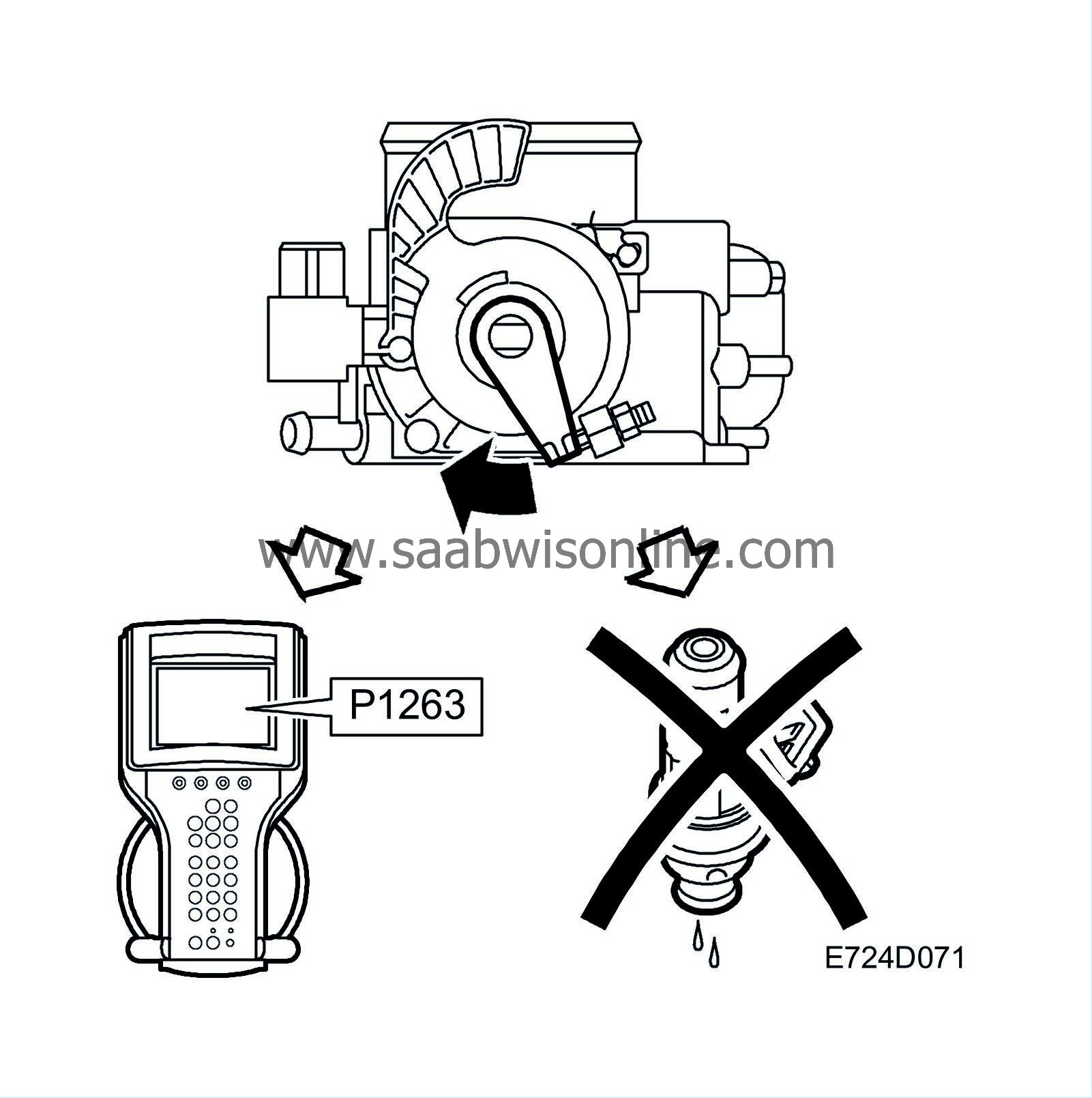
If you intend to increase engine speed from the engine bay and accidentally turn the throttle spindle instead of the pedal position sensor arm, fuel shut-off will be activated and diagnostic trouble code P1263 will be generated. The throttle control system will not go into limp-home mode, nor will the CHECK ENGINE lamp come on.
However, if the throttle spindle is rotated manually while the starter motor is cranking (e.g. during a compression test) or during the first 5 seconds after start, diagnostic trouble code P1251 will be generated and the system will go into limp-home mode.
| Miscellaneous |
| • |
The system regulates the current air mass/combustion so that it corresponds with the requested value. It is completely normal for the throttle not to be fully open despite the accelerator pedal being fully depressed.
|
|
| • |
Apart from internal control module faults, faults in the throttle control system are always localized in the throttle body or its electrical leads. The main relay must also supply control module pin 1 with current.
If there is a fault in the supply from the main relay to control module pin 1, main relay trouble code P1640 will be generated, the throttle will close and the engine will stop. |
|
| • |
The feel of the accelerator pedal is not affected in limp-home mode.
|
|
| • |
The system is self-calibrating.
|
|
| Note | ||
|
A short circuit in the 5V supply will put the system in limp-home mode and may be due to a fault in the wiring harness or in a sensor supplied with 5V. |

