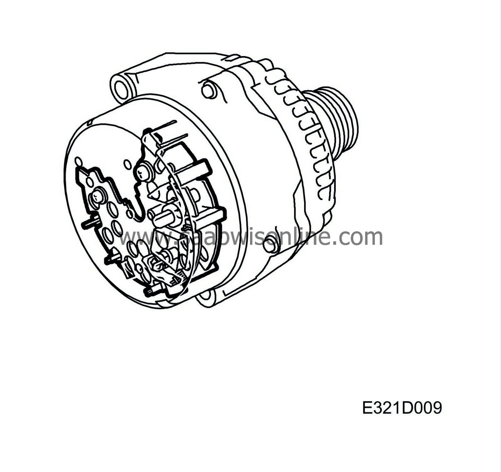
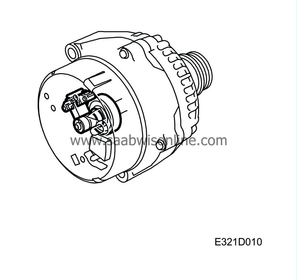
Generator design
| Generator design |
| 1. |
Stator
|
|
| 2. |
Rotor with slip rings
|
|
| 3. |
Integral fans
|
|
| 4. |
Rectifier unit
|
|
| 5. |
Voltage regulator
|
|
The generator is of the alternator type with an integrated charge regulator.
It is driven by the engine via a multigroove V-belt from the crankshaft pulley.
The gear ratio is 1:2.85.
| Stator |
The stator is integrated with the generator. It consists of grooved plates that are internally insulated and pressed together into a fixed plate assembly. The wave-formed coils of the stator winding are located in the grooves. They are delta-connected at an interval of 120° and provide three-phase alternating voltage to the rectifier.


| Rotor with slip rings |
The rotor consists of two halves (claw-type poles) that are pressed on to the rotor shaft and in mesh with one another. Each half has 12 claws, i.e., 12 poles, with one half having six north poles and the other six south poles.
The excitation winding is fixed on to the rotor shaft between the claw-pole halves.
The excitation winding consists of a circular coil surrounded by the claw poles. Exciting voltage from the regulator is fed through the brushes, which are in contact with the slip rings.
| Integral fans |


Heat that builds up in the generator when it is running can lead to damage. The generator has therefore been equipped with two integral fans driven by the rotor shaft to conduct the heat away.
The generator in a V6 engine has an additional air intake to increase the flow of air.
| Rectifier |
The current produced by the generator's stator winding must be converted to direct current before it can be used in the car's electrical system. The current is converted by means of 6 Zener diodes, 2 per phase winding.
| Voltage regulator |

The purpose of the voltage regulator is to maintain the voltage from the generator, whatever its speed and load-demand, at a constant level regardless of engine speed.
If the load causes the voltage generated to exceed the rated reference value (approx. 14 V), the regulator will reduce or break the exciting current. The generator's excitation decreases, lowering the voltage from the stator windings. When the voltage has dropped below the reference value (approx. 14 V), excitation increases, as does the generator voltage, until the reference value is once again exceeded. This process is repeated continuously.
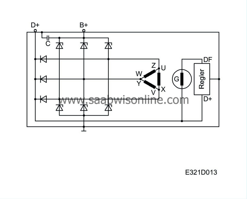
| Internal circuitry |

Six Zener diodes are used to convert the alternating voltage generated by the stator windings into direct voltage.
The stator windings form three phases and are delta-connected.
An excitation diode is connected to each of the three stator windings.
The 6 rectifier diodes are bridge-connected. The diodes are pressed into a diode retainer.
Depending on the polarity, the diode retainer is either insulated from the casing or connected directly to it. The excitation winding is mounted on to the rotor, which has claw-type poles. Alternate claws act as north poles, the remaining alternate claws as south poles.
The ends of the excitation winding are connected to slip rings over which the exciting current is fed.
| Generator, description of operation |

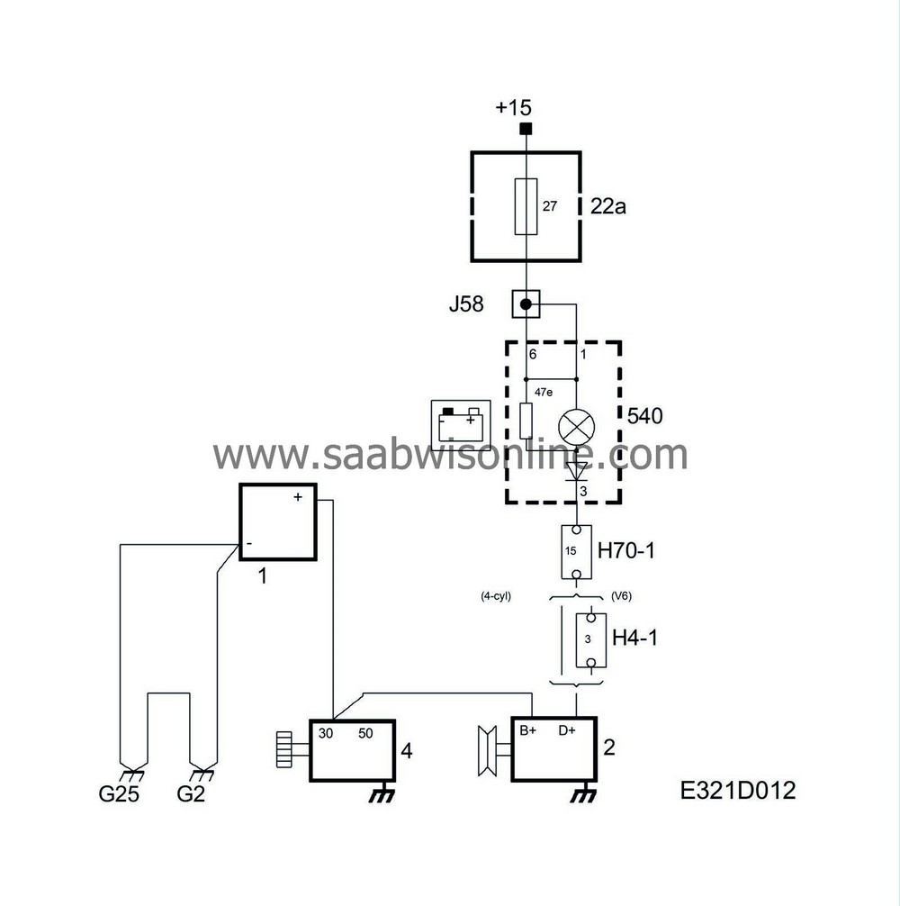
When the ignition key is turned to ON or ST, +15 is supplied to MIU.
The voltage is fed from the ignition switch via the indicator lamp to terminal D+ on the generator and from there to the rotor's excitation winding and then grounded via the regulator.
While the current is passing through the rotor, a magnetic field is formed around it. When the engine is started and the rotor starts to rotate, the magnetic field rotates as well and alternating voltage is generated in the stator winding. The alternating voltage is rectified when it passes through the diodes and is then fed to the car's electrical system. The voltage obtained from the stator winding also passes via the excitation rectifiers to the voltage regulator and influences its operation. When the voltage exceeds 14 V, the voltage regulator reduces the current through the excitation winding. The strength of the magnetic field is reduced as is the alternating voltage in the stator winding.
The charging indicator lamp is also influenced by the voltage from the stator winding via terminal D+ on the regulator. The difference in voltage between the two sides of the charging indicator lamp levels out and the lamp goes out. In this way, an indication is obtained that the generator is charging.


