Bus communication
| Bus communication |
P-bus and I-bus
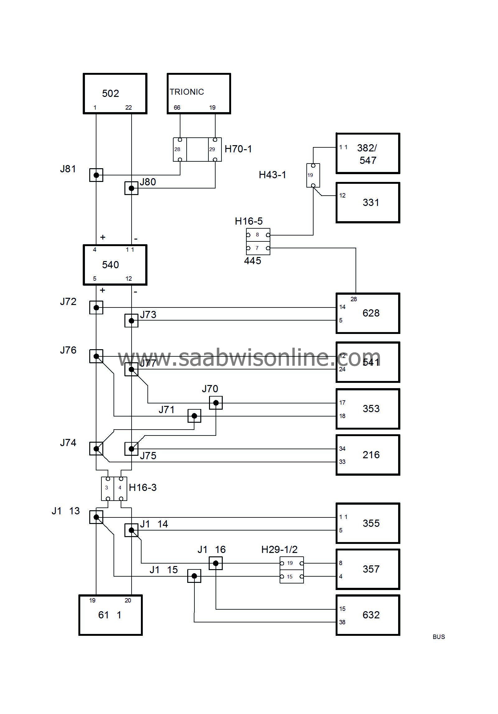
Two bus information systems, the Powertrain bus (P-bus) and the Instrument bus (I-bus), are connected to each other in the main instrument unit (MIU). The two buses are electrically separate. The data transfer rate of the P-bus is 10 times faster than that of the I-bus.All the information sent out from a control module is available to all other bus-connected control modules. The MIU sees to it that information which is available on one bus is also available on the other bus.
The control modules send out information on the buses are regular times. The interval between two transmissions depends on the type of information transmitted and varies between 10 milliseconds (0.010 seconds) and one second. The information is also transmitted by the control modules each time a change occurs in it.
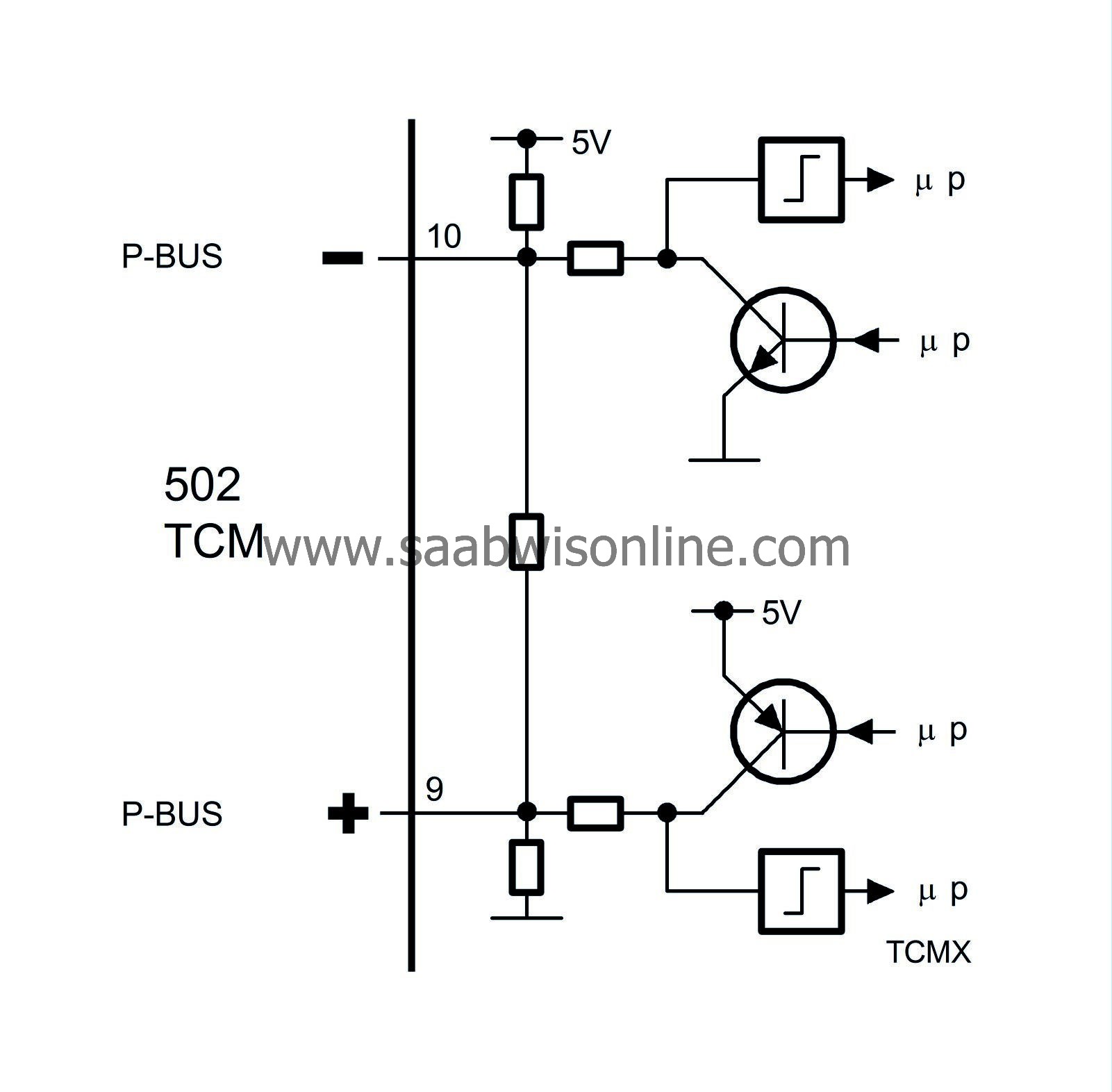
The information is transferred between control modules via two leads, BUS+ (green lead) and BUS- (white lead). The leads of the P-bus are twisted to reduce their sensitivity to electrical interference.

Diagnostics
In a bus communication system, it is necessary for all units to be capable of communicating with each other. For example, the engine cannot be started unless the Trionic system can receive the immobilization information transmitted by TWICE.Permanent bus faults
All Tech2 communication with bus-connected systems takes place via DICE. Regardless of which system is contacted, the Tech2 instrument will first check with the aid of DICE that all the car's bus-connected systems are active and in communication. If any bus-connected control module is not present, this will be shown on the Tech2. This means that all bus-connected control modules are in proper communication unless the Tech2 indicates otherwise.Intermittent bus faults
The Trionic system and TCM continuously check that all control modules from which they obtain information communicate correctly. In the event of an intermittent bus communication fault, diagnostic trouble codes will be generated in the Trionic system and TCM. The cause of the fault could be that the control module in question has lost its power supply or one of the bus leads.Incorrect values on the bus
A diagnostic trouble code will be generated in the Trionic system and TCM if any information they receive on the bus has an incorrect value. In the diagnostic trouble code text, reference is made to the system in which the fault is present.For further information on the bus, see Buss and Diagnostics Communication.
| The TCM uses the following information: |
| Information | Unit | Sensor system | Description |
| Engine torque | Nm | Trionic | The current air mass/combustion is converted into torque and given in Nm. |
|
Pedal position
|
%
|
Trionic
|
The highest air mass/combustion value requested from the pedal position or Cruise Control system is selected. The value is converted into a corresponding pedal position and given as a percentage, unit %.
|
|
Kickdown
|
ON/OFF
|
Trionic
|
When the voltage from pedal potentiometer 1 corresponds to the kickdown position (below 1.50 V), Kickdown ON will be sent.
|
|
Engine speed
|
rpm
|
Trionic
|
Current engine speed, unit rpm.
Additionally, the value is used to compare engine speed with the speed of the input shaft when Lock-up is activated. If the difference between engine speed and input shaft speed is greater than 100 rpm, diagnostic trouble code P0741 will be generated. |
|
Brake lights
|
ON/OFF
|
TWICE
|
Brake lights, unit ON/OFF.
|
| The TCM sends the following information: |
| Information | Unit | Used by | Description |
|
Maximum permissible torque
|
Nm
|
Trionic
|
The TCM sends the maximum permissible torque, unit Nm. The value is used in the mass air flow control circuit for torque limitation.
|
|
SPORT
|
ON/OFF
|
Trionic, MIU
|
The TCM sends the sport position, unit ON/OFF. The value is used in the mass air flow control circuit to correct the pedal position's conversion into the requested air mass/combustion. The MIU causes the SPORT indicator lamp to light up.
|
|
Selector lever position
|
P, R, N, D, 3, 2, 1
|
Trionic, MIU
|
The TCM sends the selector lever position, unit P, R, N, D, 3, 2 and 1. The Trionic system uses the value in the mass air flow control circuit for idle speed control. The MIU uses the value to light up the relevant segment in the selector lever display.
|
|
CHECK GEARBOX lamp
|
ON/OFF
|
MIU
|
ON is sent when on-board diagnostics reports that the lamp should be lit, unit ON/OFF. The value is used by MIU.
|
|
WINTER lamp
|
ON/OFF
|
MIU
|
When the WINTER driving program is selected, WINTER ON information is sent, unit ON/OFF. The MIU causes the WINTER indicator lamp to light up.
|
|
Message HIGH GEARBOX FLUID TEMP
|
Text message
|
SID
|
When the transmission fluid temperature exceeds 160°C, HIGH FLUID TEMP AUT TRANSMISSION ON, unit ON/OFF is sent. The SID unit will display this message.
|


