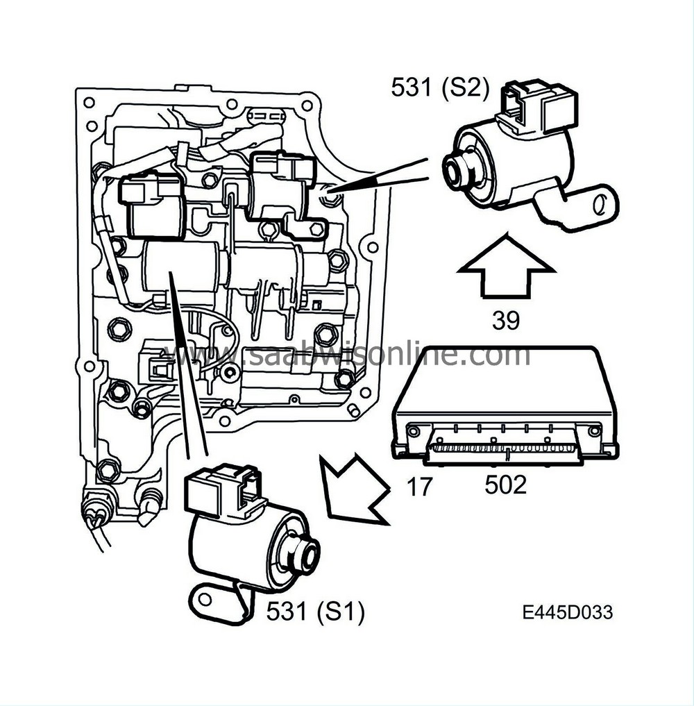
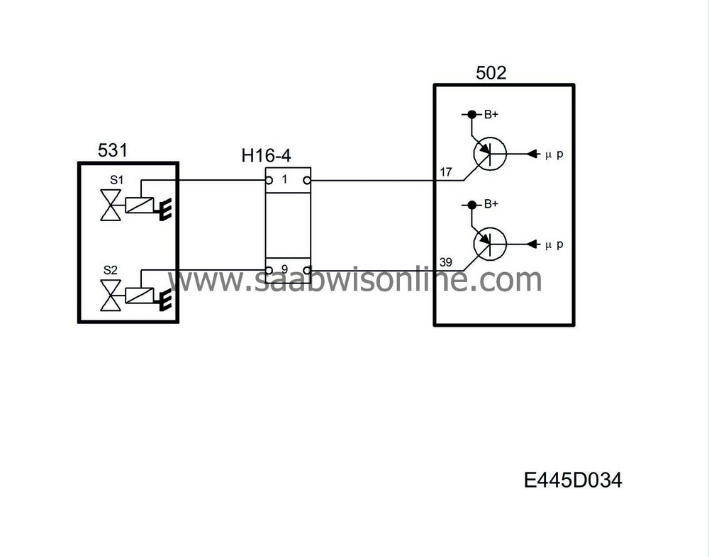
Solenoid valves, S1 and S2, for shifting
| Solenoid valves, S1 and S2, for shifting |
Solenoid valves S1 and S2 are located in the valve housing, which is mounted on the gearcase. The two solenoid valves control the hydraulic shifting valves by opening and closing the return flow that provides system pressure for the relevant shifting valve.
The solenoids are grounded via their casing directly to the valve housing and the control module activates the relevant solenoid by supplying it with battery voltage B+. A solenoid not supplied with current is closed. Solenoid S1 is connected to control module pin 17 and solenoid S2 is connected to control module pin 39.
The control module activates the appropriate valve for upshifting or downshifting depending on the input/output speed, accelerator position and selected driving program.
Operation of the solenoids (S1 and S2) in regard to the selector lever positions is as follows:

|
Selector lever position
|
S1
|
S2
|
|
1
|
OFF (0 V)
|
ON (B+)
|
|
2
|
ON (B+)
|
ON (B+)
|
|
3
|
ON (B+)
|
OFF (0 V)
|
|
4
|
OFF (0 V)
|
OFF (0 V)
|
The nominal winding resistance in the solenoids is 13 ohms. Solenoids S1 and S2 are identical (of the same type).
Diagnostics
Diagnostic trouble code P0753 will be generated in the event of a fault in solenoid S1.Diagnostic trouble code P0758 will be generated in the event of a fault in solenoid S2.
In both cases the transmission will go into Limp-Home mode.


