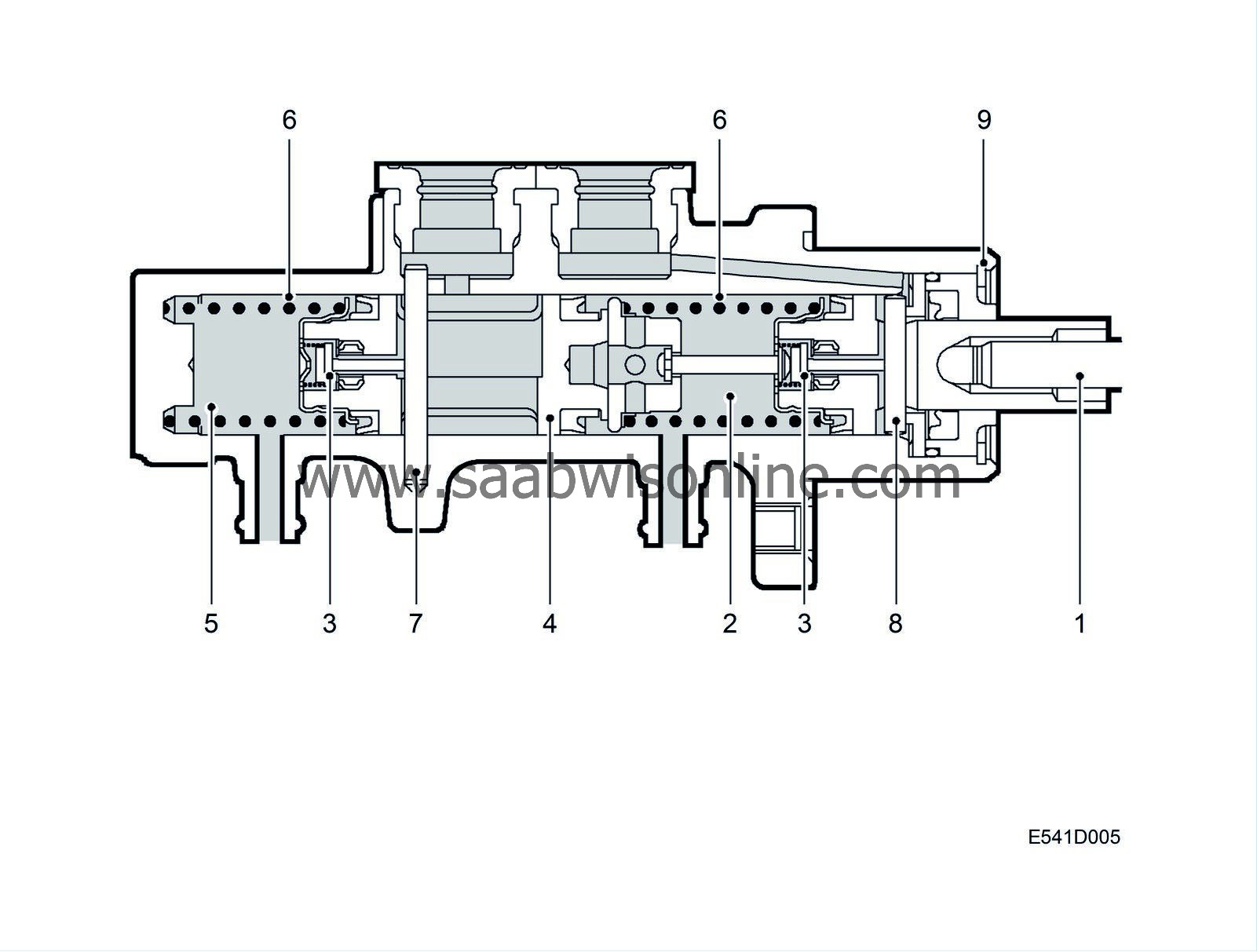
Master cylinder
| Master cylinder |
| 1. |
Pushrod with primary piston
|
|
| 2. |
Pressure chamber (primary circuit)
|
|
| 3. |
Central valves
|
|
| 4. |
Secondary piston
|
|
| 5. |
Pressure chamber (secondary circuit)
|
|
| 6. |
Return springs
|
|
| 7. |
Stop pin (secondary circuit)
|
|
| 8. |
Stop pin (primary circuit)
|
|
| 9. |
Retaining ring
|
|
The master cylinder is a tandem cylinder which is made of aluminium.
Inside the master cylinder are two pistons, a primary piston (1) (nearest the brake pedal) and a secondary piston (4). There are also return springs (6) for these pistons. Each pressure chamber (2, 5) has one connection to a brake line and one connection to the brake fluid reservoir.
The purpose of the two central valves (3) is to open the passages to the pressure chambers for the primary and secondary pistons in the rest (brakes not applied) position and to close the passages when the brake pedal is depressed. To resist the high pressure in the master cylinder, the central valves are made of steel.
| Rest (brakes off) position |

| 1. |
Pushrod with primary piston
|
|
| 2. |
Pressure chamber (primary circuit)
|
|
| 3. |
Central valves
|
|
| 4. |
Secondary piston
|
|
| 5. |
Pressure chamber (secondary circuit)
|
|
| 6. |
Return springs
|
|
| 7. |
Stop pin (secondary circuit)
|
|
| 8. |
Stop pin (primary circuit)
|
|
| 9. |
Retaining ring
|
|
In the rest (brakes not applied) position, the return springs (6) press the pistons (1, 4) towards the rear end position. In this position, both return passages are open (via the central valves (3)) and the brake system is without pressure. A retaining ring (9) prevents rearward movement of the primary piston and a stop pin (7) prevents rearward movement of the secondary piston. A stop pin (8) opens the primary piston's central valve when the piston is in the rest (brakes off) position. The secondary piston's central valve is opened in the rest (brakes off) position by the stop pin (7), which also limits rearward movement of the piston.
The master cylinder and other hydraulic components are filled with brake fluid under zero pressure.
Volume equalization in the system is now possible in the event of a change in the temperature of the brake fluid or heavy brake pad wear.
| Brakes applied (both circuits operative) |

| 1. |
Pushrod with primary piston
|
|
| 2. |
Pressure chamber (primary circuit)
|
|
| 3. |
Central valves
|
|
| 4. |
Secondary piston
|
|
| 5. |
Pressure chamber (secondary circuit)
|
|
| 6. |
Return springs
|
|
| 7. |
Stop pin (secondary circuit)
|
|
| 8. |
Stop pin (primary circuit)
|
|
| 9. |
Retaining ring
|
|
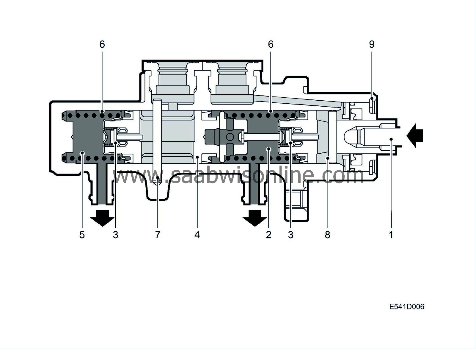
The primary piston's central valve (3) leaves the stop pin (8), closing the return flow and causing the pressure in front of the primary piston to increase. The increased pressure also acts on the secondary piston (4), which is pushed forwards with the result that its central valve (3) leaves the stop pin (7) and closes.
The hydraulic pressure in both brake circuits increases, and since the pistons are the same size the pressure in both brake circuits is the same.
The pressure is propagated through the brake system and acts on the brake piston in each brake hydraulic body. The brake pistons press the brake pads against the brake discs.
When the brake pedal is released, the pistons in the master cylinder return and the central valves open. The pressure is relieved and the brake piston in each brake cylinder is returned to the rest (brakes off) position by the piston sealing ring.
| Brakes applied (one circuit inoperative) |

| 1. |
Pushrod with primary piston
|
|
| 2. |
Pressure chamber (primary circuit)
|
|
| 3. |
Central valves
|
|
| 4. |
Secondary piston
|
|
| 5. |
Pressure chamber (secondary circuit)
|
|
| 6. |
Return springs
|
|
| 7. |
Stop pin (secondary circuit)
|
|
| 8. |
Stop pin (primary circuit)
|
|
| 9. |
Retaining ring
|
|
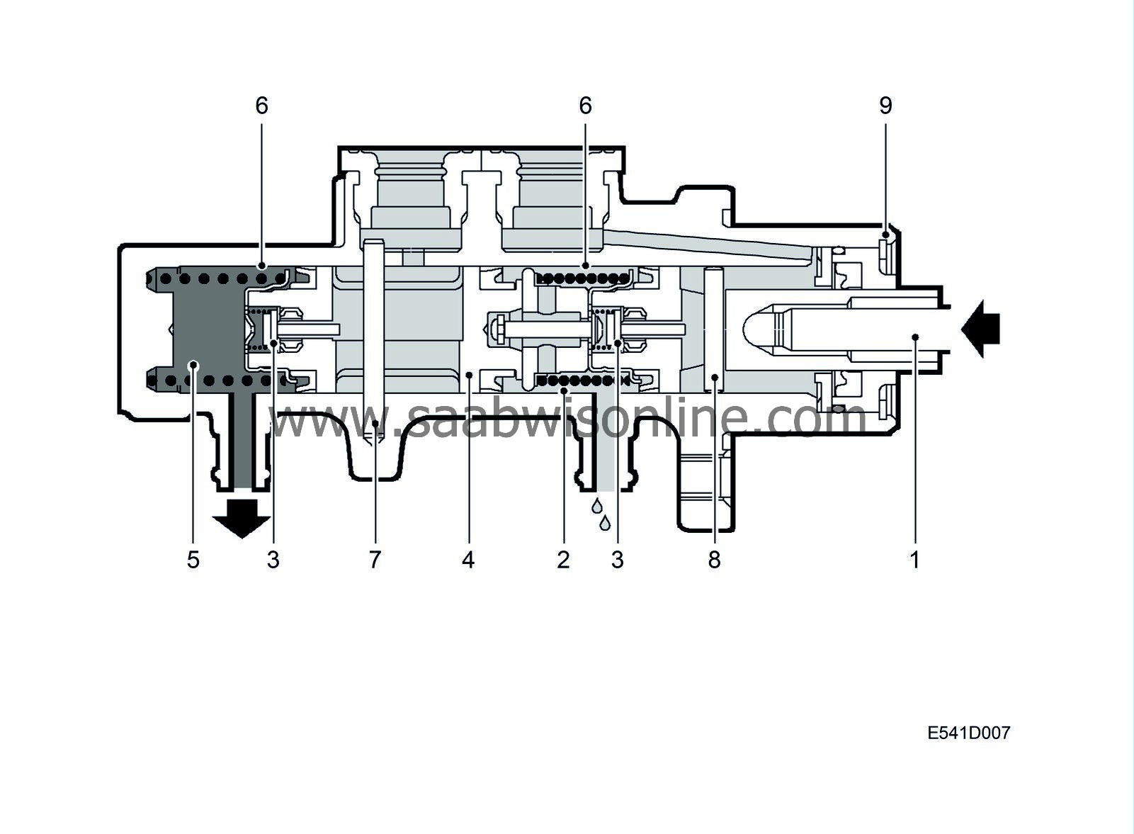
If leakage occurs in the primary circuit:
The primary piston is pressed forwards by the pushrod until it acts mechanically on the secondary piston. The secondary piston leaves the stop pin, causing the central valve to close. Hydraulic pressure then builds up in the secondary circuit. Braking power is obtained in the secondary circuit only (front right and rear left).
If leakage occurs in the secondary circuit:
The primary piston leaves the stop pin, causing the central valve to close and hydraulic pressure builds up in the primary circuit.
The secondary piston is pressed forwards and will bottom in the master cylinder. Braking power is obtained in the primary circuit only (front left and rear right).
In both cases, longer pedal travel will be required to achieve the desired braking power.


