ABS function
| ABS function |
| 1. |
Braking force
|
|
| 2. |
Stable braking zone
|
|
| 3. |
Unstable braking zone
|
|
| 4. |
Slip
|
|
The ABS system provides optimum braking without any loss of directional stability.


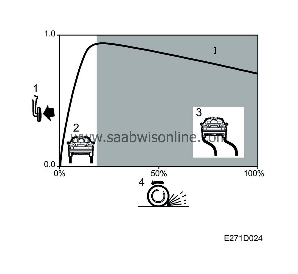
Braking force/tyre slip
Diagram 1 shows the braking force as a function of slip.Vertical axis = Braking force
Horizontal axis = Slip
The braking force is equivalent to the coefficient of adhesion or the friction between the tyre and the road surface. Each application of braking force gives rise to a certain degree of slip. The slip of a freely rotating wheel is expressed as 0% and of a locked wheel as 100%.
When the brake is first applied at 0% slip, braking force increases sharply but the degree of slip increases only gradually up to a certain limit. Beyond that point, braking force decreases with increasing slip.
Information on the rotational speed of each wheel comes from the wheel sensors. The TC/ABS control module measures the reference speed, normally on the fastest-rotating rear wheel. The reference speed is subsequently used to determine whether any wheel is exceeding the slip threshold.
| 1. |
Lateral force
|
|
| 2. |
Stable braking zone
|
|
| 3. |
Unstable braking zone
|
|
| 4. |
Slip
|
|
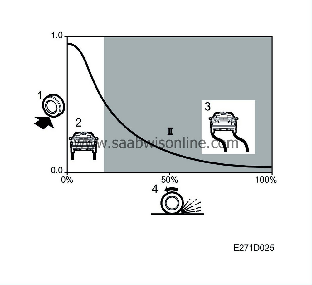
Lateral force/Slip
Diagram 2 shows lateral force as a function of slip.Vertical axis = Lateral force
Horizontal axis = Slip
The maximum braking force is reached at a point known as the limit of optimum slip. The section of the curve between 0% slip and the limit of optimum slip is called the stable braking zone, and the section of curve between the limit of optimum slip and 100% slip is called the unstable braking zone, as stable braking cannot be achieved within this zone. This is because the wheel quickly becomes locked after the limit of optimum slip has been reached, unless the braking force is immediately reduced.
Slip also occurs when the tyre is called upon to transmit a lateral force, e.g. on cornering. Diagram 2 shows how the lateral force falls away sharply with increasing slip. At 100% slip (i.e. when the wheels have locked up) no lateral force remains for steering and the driver will no longer be able to control the vehicle.
The TC/ABS control module measures and compares the rotational speed of each rear wheel and this enables it to determine whether the car is being driven straight ahead or round a bend.

| 1. |
Braking/lateral force
|
|
| 2. |
Stable braking zone
|
|
| 3. |
Unstable braking zone
|
|
| 4. |
ABS operating range
|
|
| 5. |
Limit of optimum slip
|
|
| 6. |
Slip
|
|
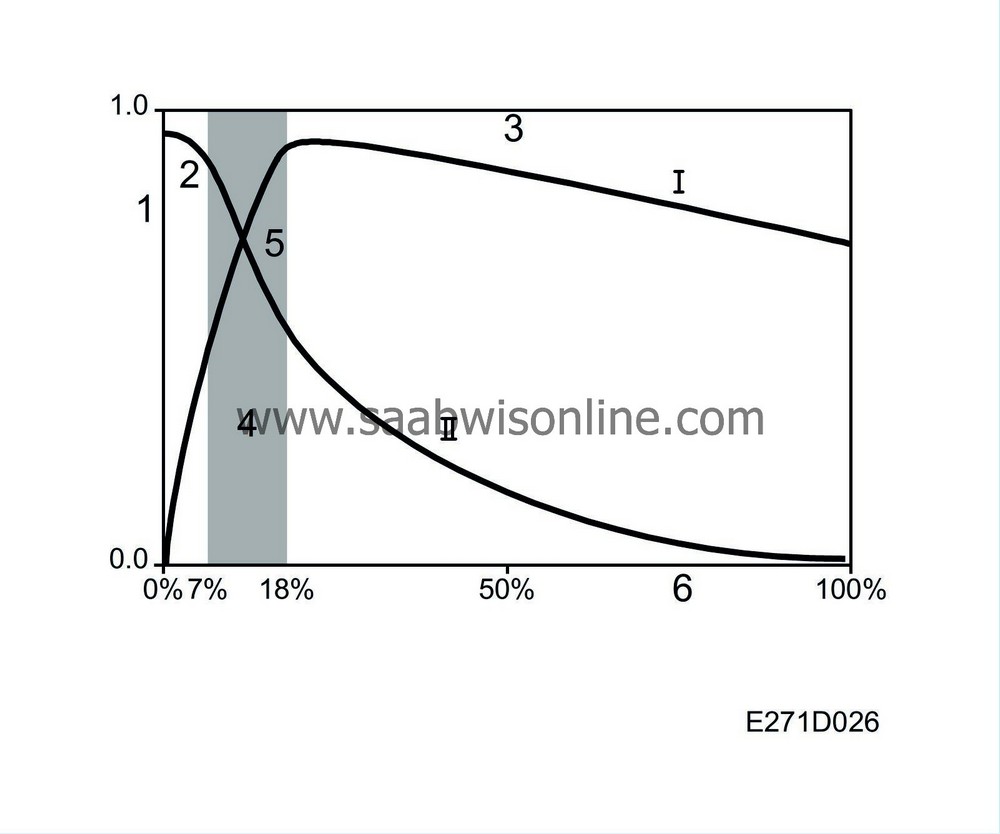
Both curves are shown on the above graph and the range within which the ABS function is operative has been superimposed. During braking, the system allows braking force to increase to a point just before the limit of optimum slip and then prevents it from increasing further. The system then modulates the hydraulic pressure to keep the braking force as close as possible to the optimum value (the limit of optimum slip) regardless of how hard the brake pedal is depressed.
Thus, because the ABS system prevents the degree of slip from exceeding the limit of optimum slip, the car never enters the unstable braking zone. At the same time, some lateral force is preserved to ensure that steering control can be maintained (curve II).
Depending on the friction of the road surface and the speed of the car, the TC/ABS control module modulates the permissible slip between 7% and 18%.


