(644-1904) Leaking power steering line
|
MODIFICATION INSTRUCTION
|
|
Bulletin Nbr:
|
644-1904
|
|
Date:
...........
|
APRIL 1998
|
|
Market:
|
ACCORDING TO SEPARATE LIST
|
|
|
Leaking power steering line
|
Cars in stock must be rectified before delivery.
Cars already delivered must be rectified the next time that they are bought to the workshop for regular service or repair.
Saab 9-5 M98 with VIN W3050321 up to and including W3054696. Replacement of front and rear delivery lines.
Saab 9-5 M98 from W3054697 up to and including W3059051. Replacement of rear delivery line and O-ring on the connection of the front delivery line to the servo pump.
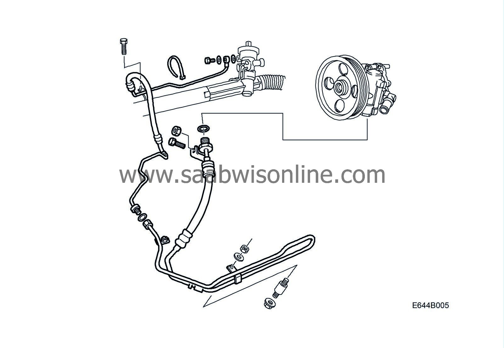
There is a risk of fluid leaks from the power steering system delivery line in the affected cars. The fluid leak occurs in the form of moisture around the crimp hoses which can develop to drop leakage.
Following a longer period of drop leakage, the fluid level will drop in the reservoir to under the minimum level. This results in considerable noise from the power steering system due to the air mixture in the fluid.
The fluid leakage is caused by the inferior quality of the crimp joints between the rubber hose and the pipe
LHD (W3050321-W3050848)
50 59 035 Delivery line, front
50 59 019 Delivery line, rear
LHD (W3050849-W3054696)
50 59 043 Delivery line, front
50 59 019 Delivery line, rear
LHD (W3054697-W3059051)
50 59 019 Delivery line, rear
RHD (W3050321-W3050848)
50 59 035 Delivery line, front
50 59 027 Delivery line, rear
RHD (W3050849-W3054696)
50 59 043 Delivery line, front
50 59 027 Delivery line, rear
RHD (W3054697-W3059051)
50 59 027 Delivery line, rear
(16) 30 32 380 Power steering fluid 0.5 l
Before starting any work, check box A2 of the modification identity plate. If not marked, continue according to the following.
Replacement of rear pressure delivery line
To remove
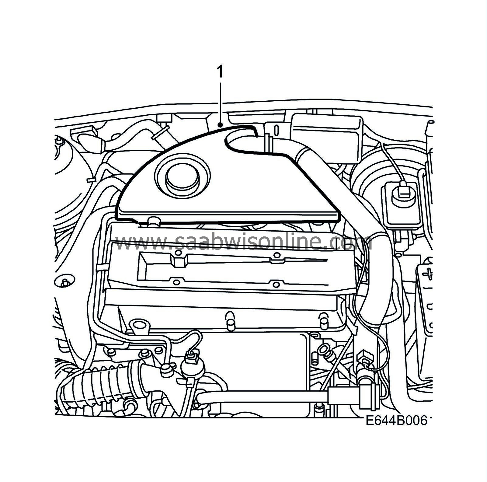
|
1.
|
Remove the engine cover.
|
|
2.
|
Remove the nut for the rear engine mounting.
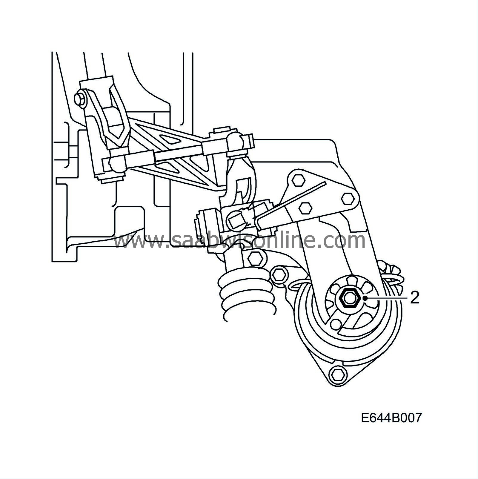
|
|
3.
|
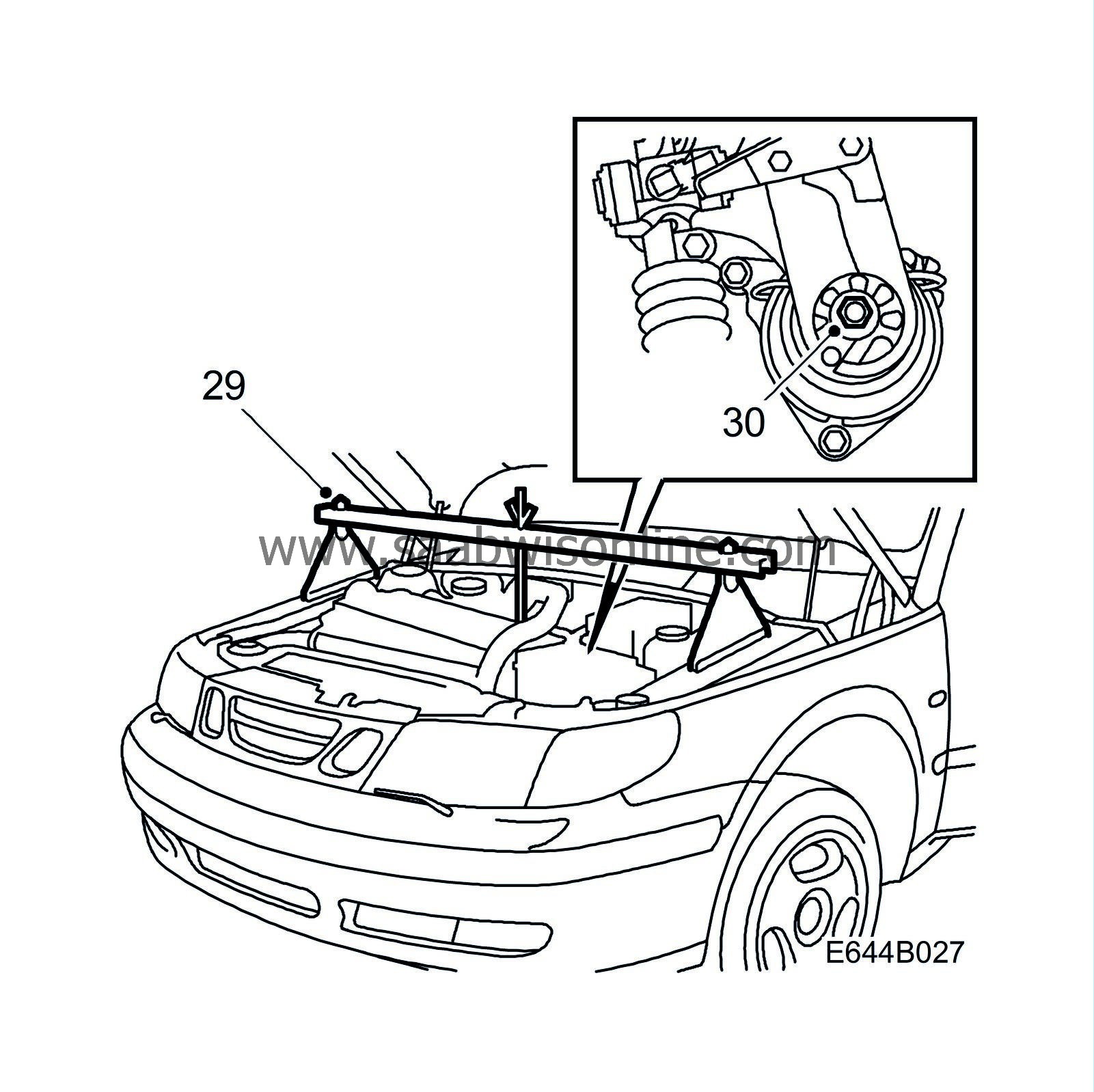
Relieve the engine unit with a lifting beam, part number 83 94 850.
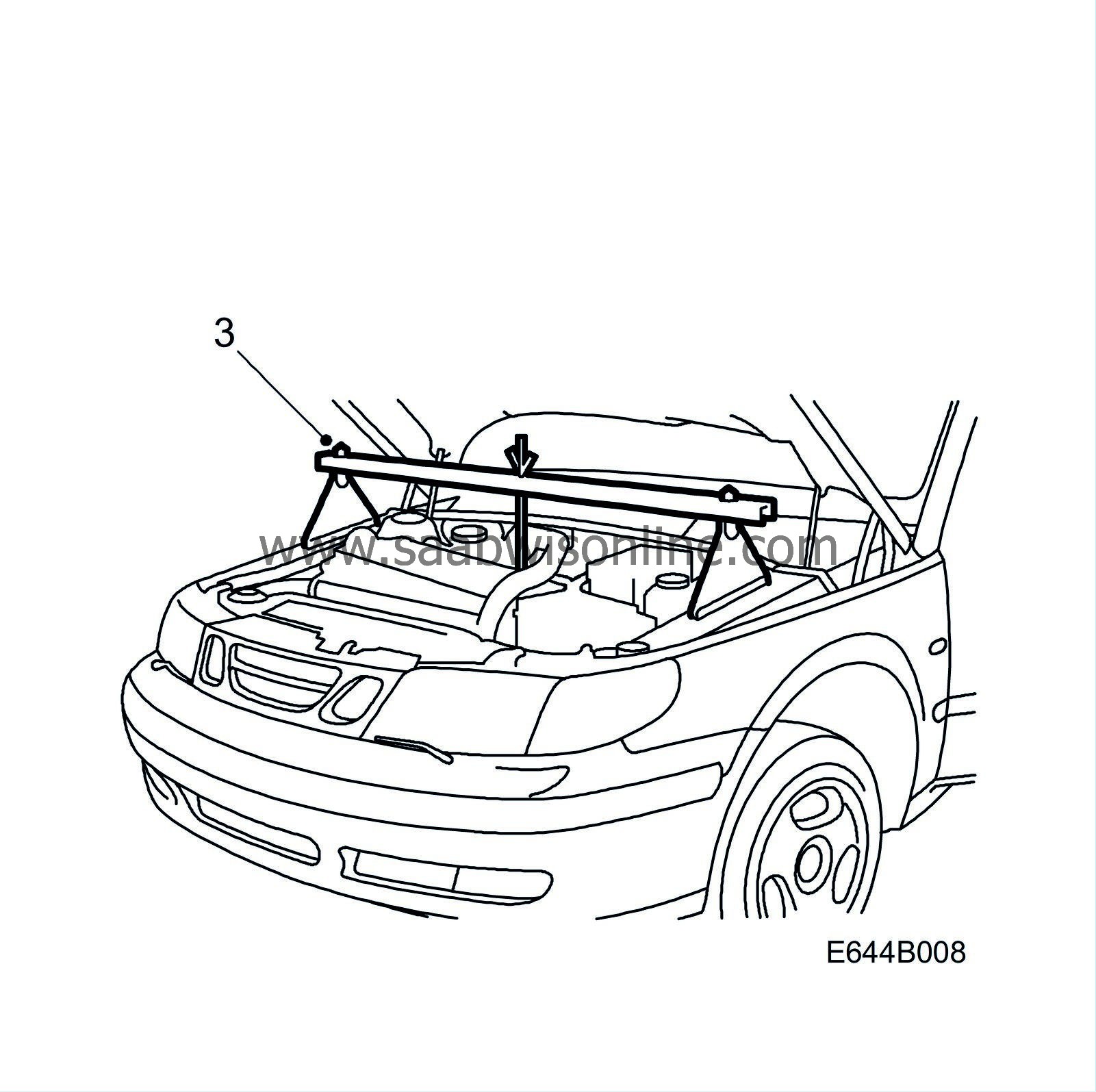
|
|
4.
|
Clamp shut the suction and return hoses (2 pcs), part number 30 07 739.
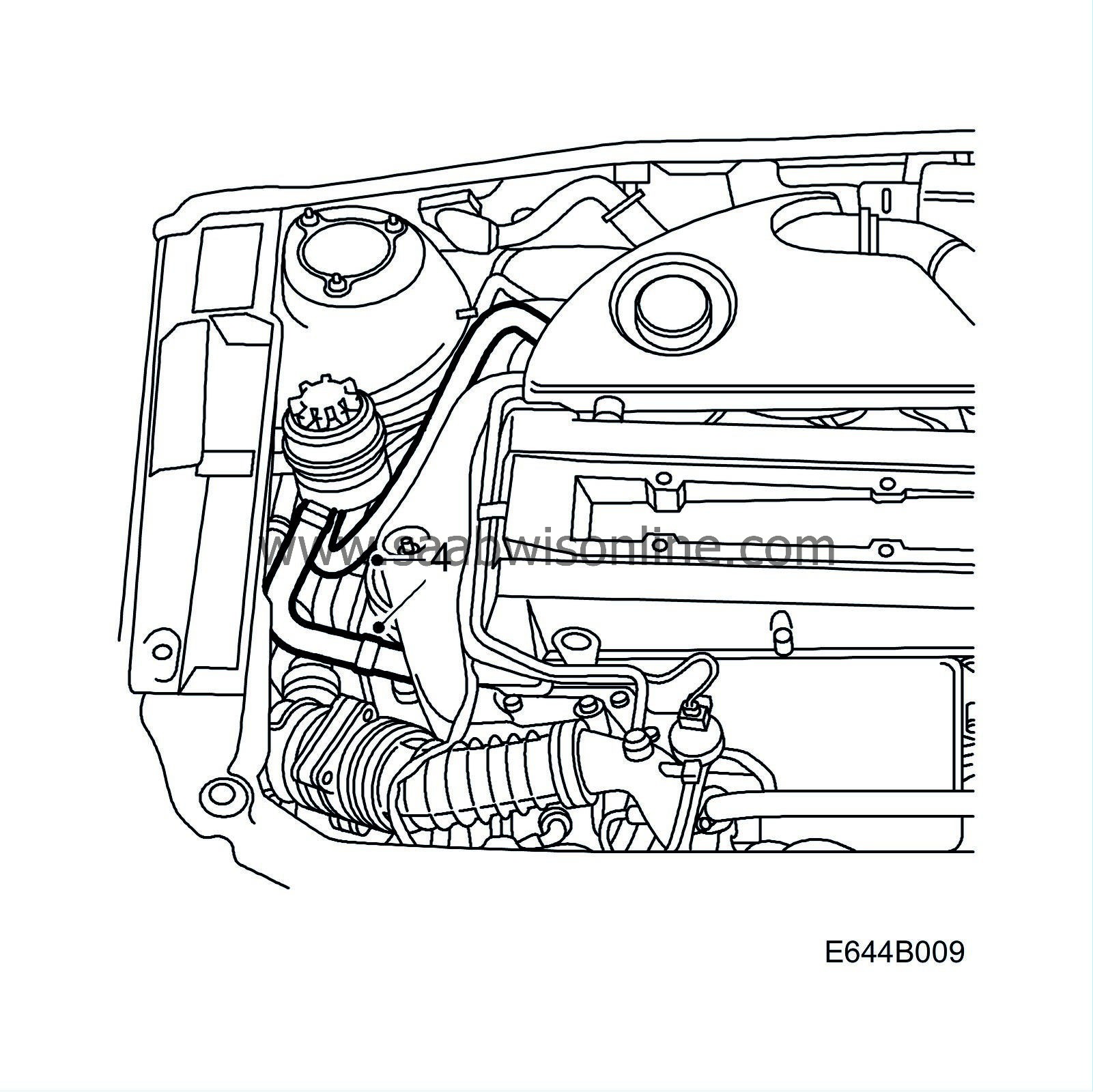
|
|
5.
|
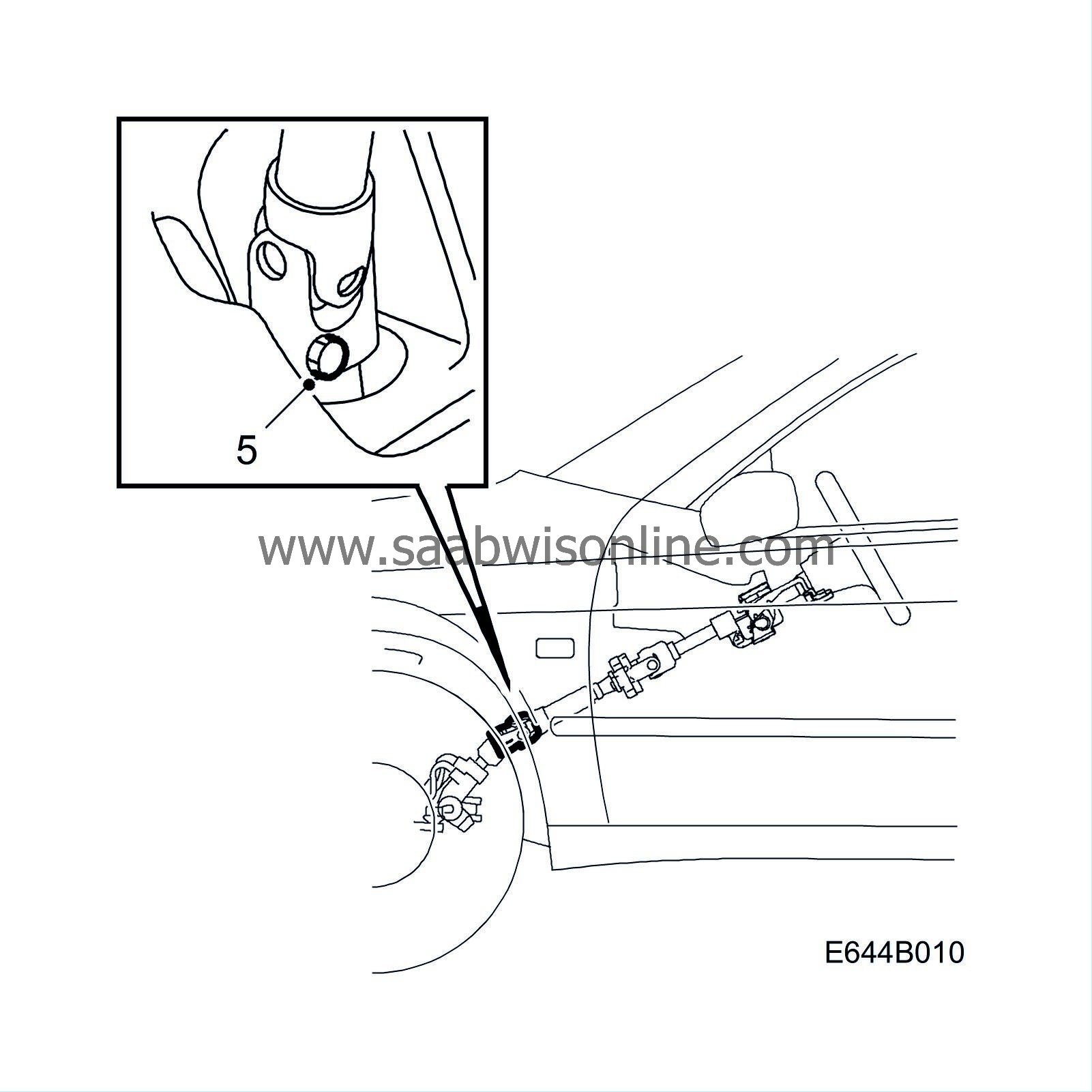
Turn the steering wheel straight and loosen the steering column joint from the steering gear. Fixate the steering wheel.
 Warning
|
|
Secure the steering wheel to avoid twisting the coil spring to such an extent that it breaks.
|
|
|
|
|
|
|
|
7.
|
Remove the right-hand cover.
|
|
8.
|
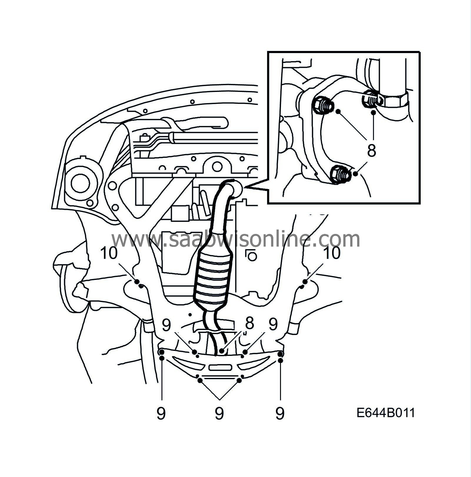
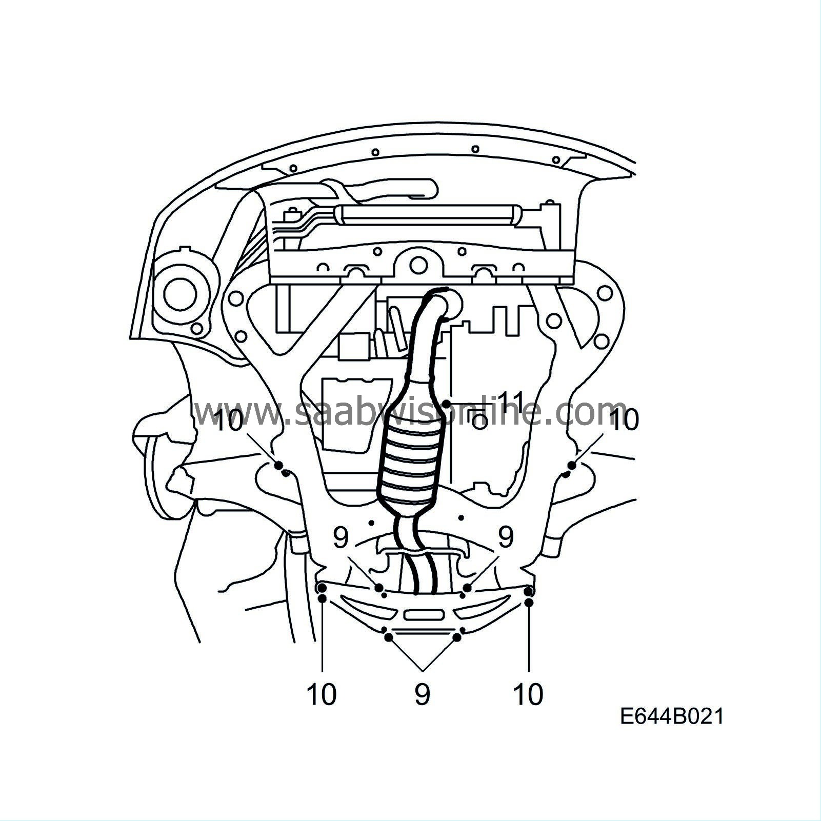
Part the exhaust pipe joint and undo the nuts against the turbo so that the pipe can twist when the rear part of the subframe is lowered.
|
|
9.
|
Remove the reinforcement plates.
|
Important
|
|
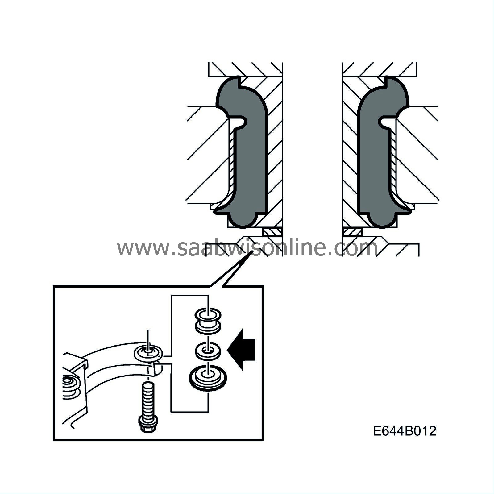
Retain the washers for VIN up to and including W3050999
|
|
|
|
|
10.
|
Slightly lower the subframe by removing the centre bolts.
|
Important
|
|
Retain the washers for VIN up to and including W3050999
|
|
|
|
|
11.
|
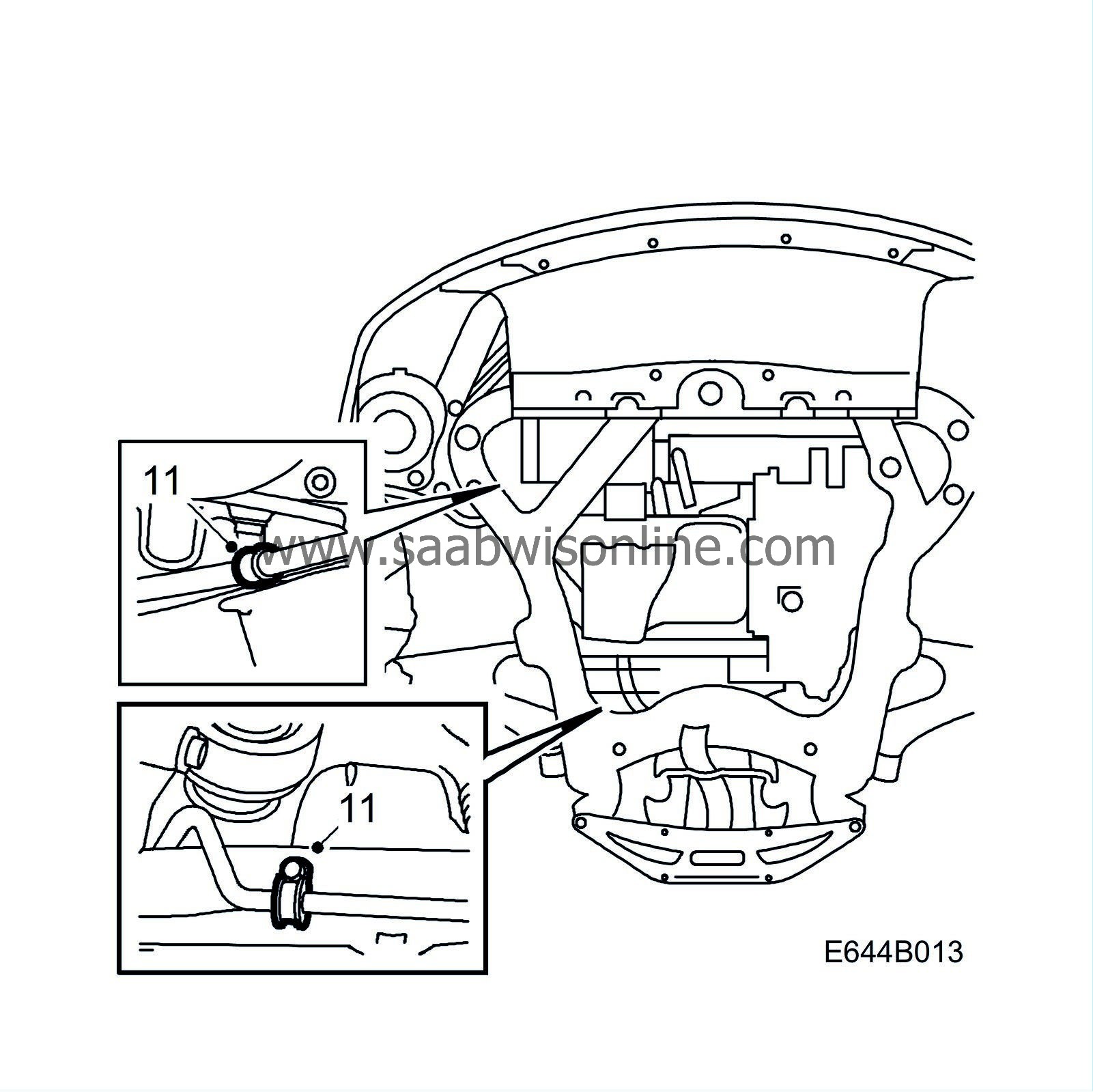
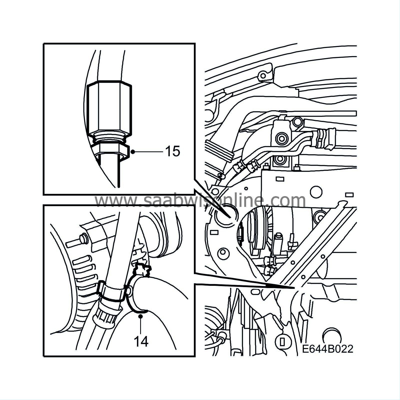
Remove the 2 clamps on the rear line. Remove any washers positioned under the clamps, they are not to be refitted.
|
|
12.
|
LHD:
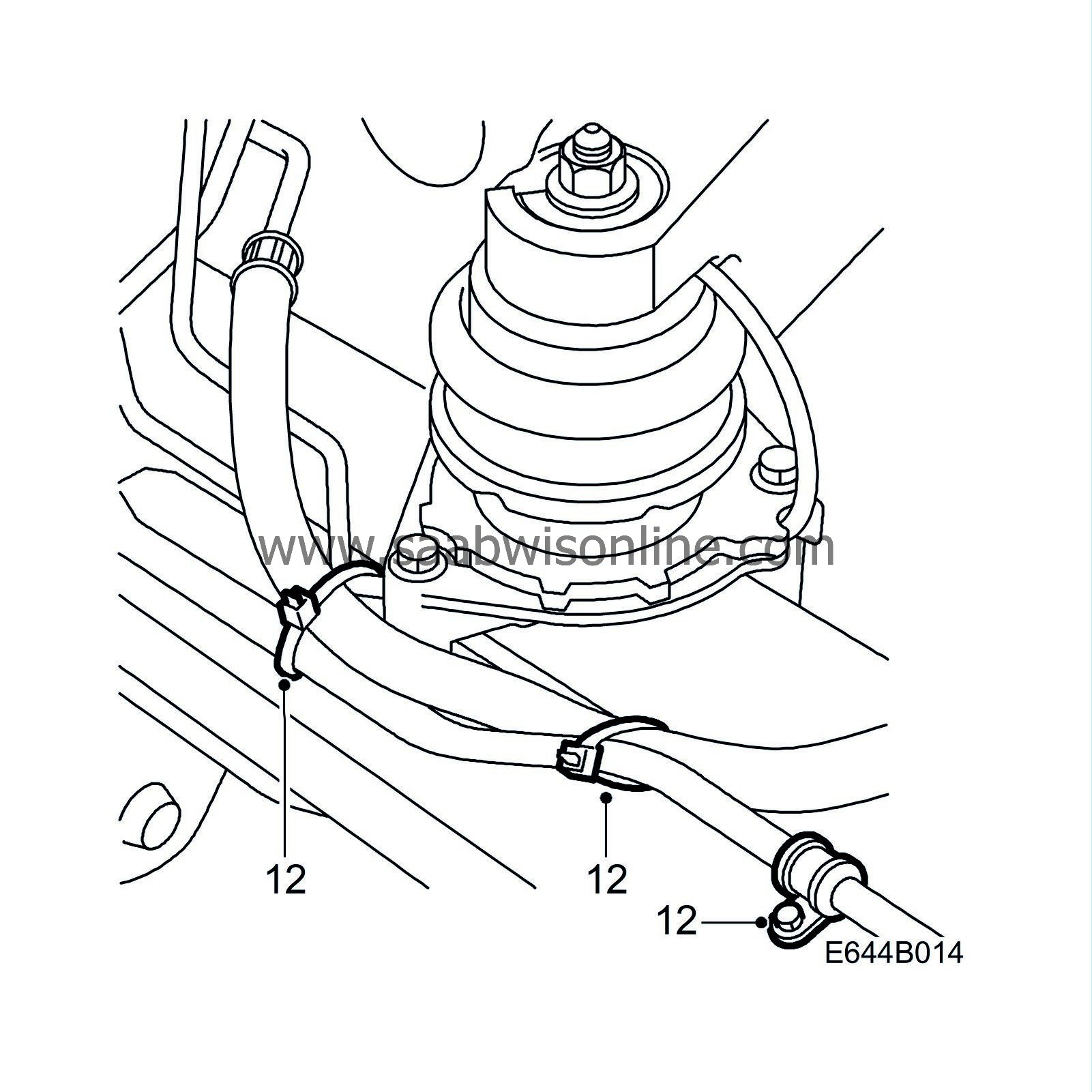
Undo the two cable ties on the rear line and the clamp securing the line to the steering gear mounting.
|
|
13.
|
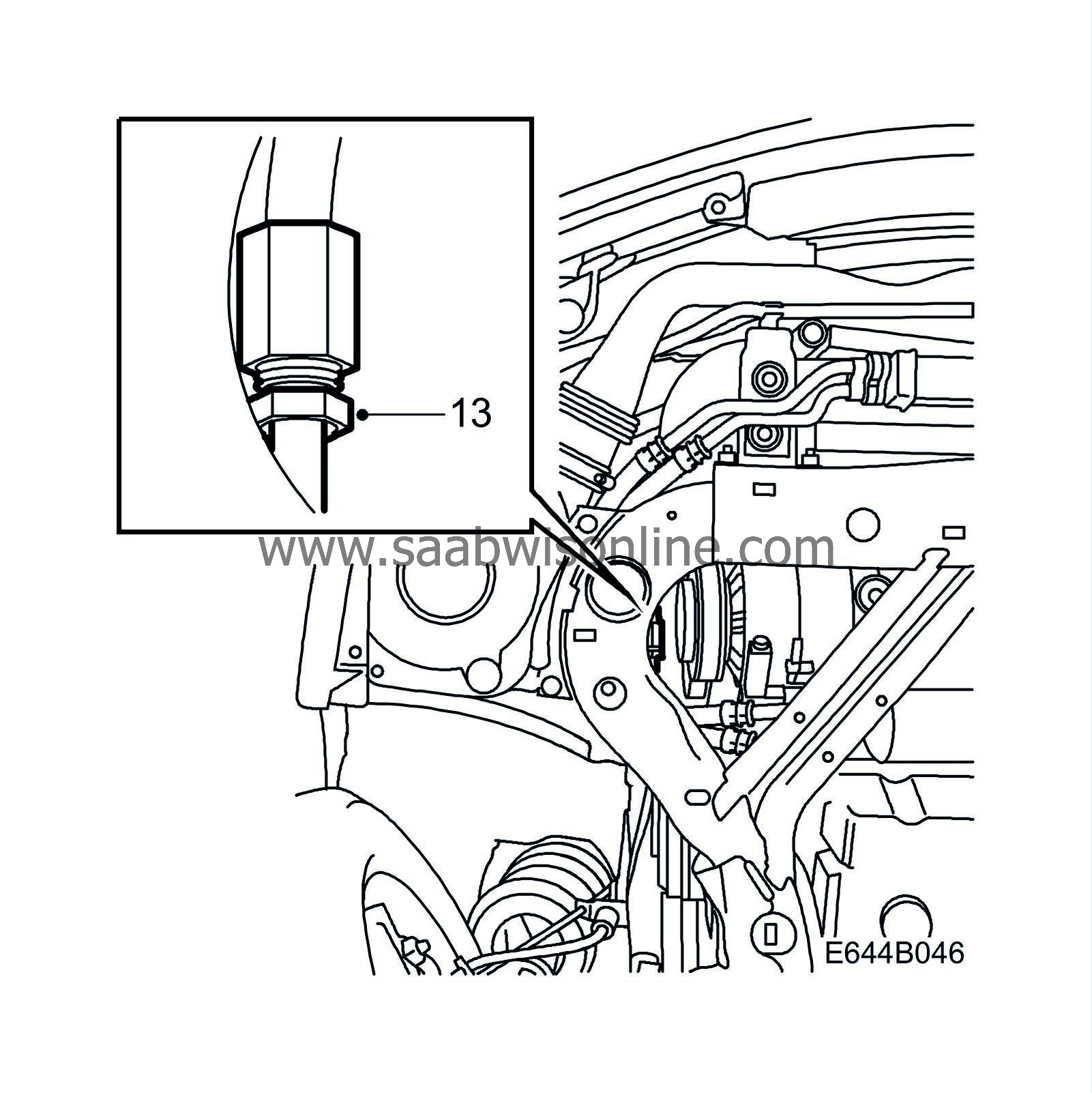
Part the delivery line at the joint. Position a container underneath to collect the fluid that drains.
|
|
14.
|
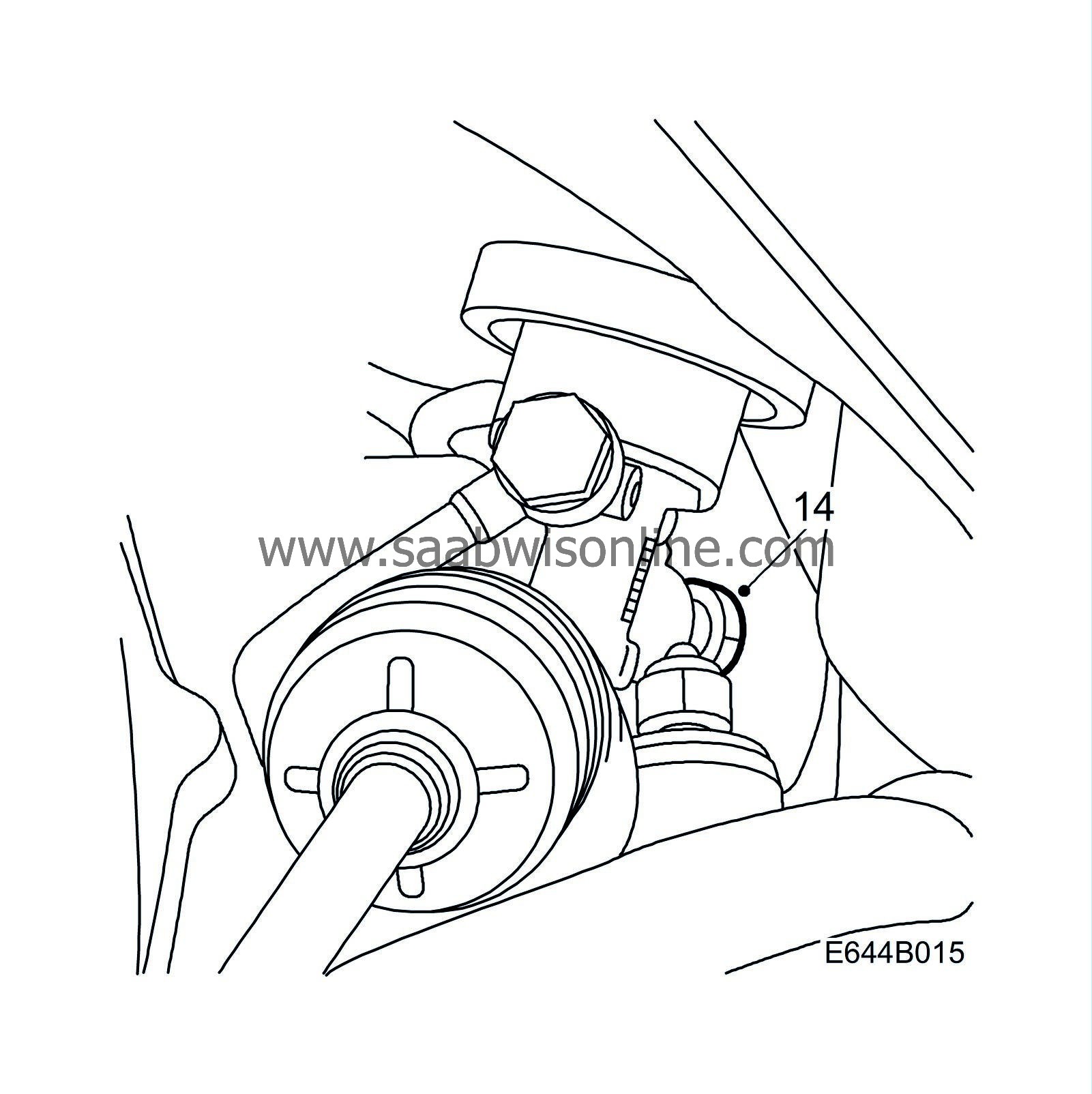
Remove the banjo nipple by the steering gear. Position a container underneath to collect the fluid that drains.
|
|
15.
|
LHD:
Turn down the front part of the rear line and remove the pipe. (More fluid will drain.)
|
|
16.
|
RHD:
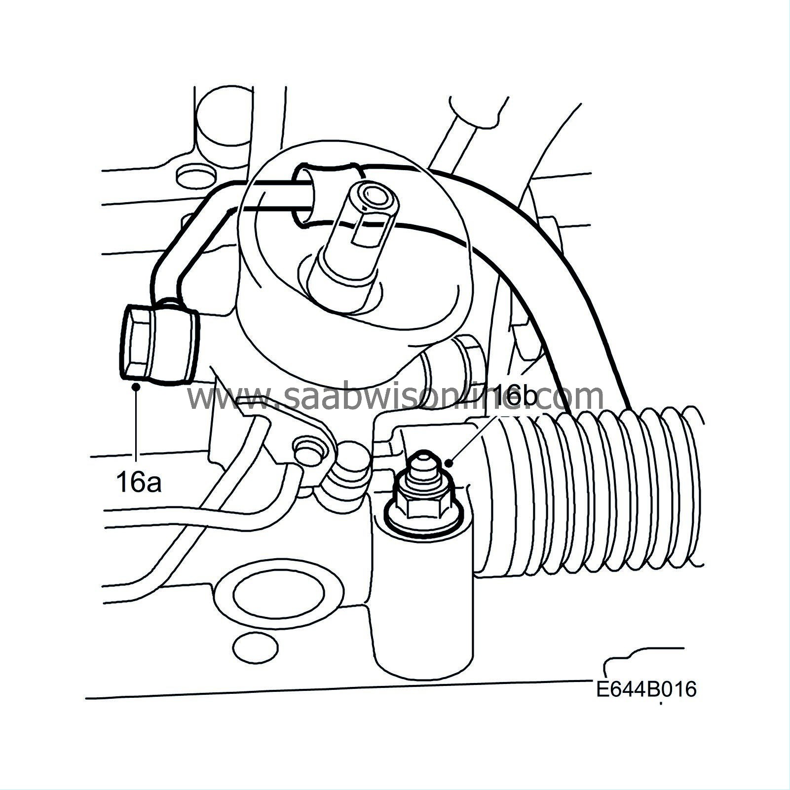
|
|
|
16.a.
|
Turn down the rear part of the rear line and remove the pipe. (More fluid will drain.)
|
|
|
16.b.
|
Undo the bolt securing the steering gear to the subframe on the right-hand side.
|
To fit
|
1.
|
RHD:
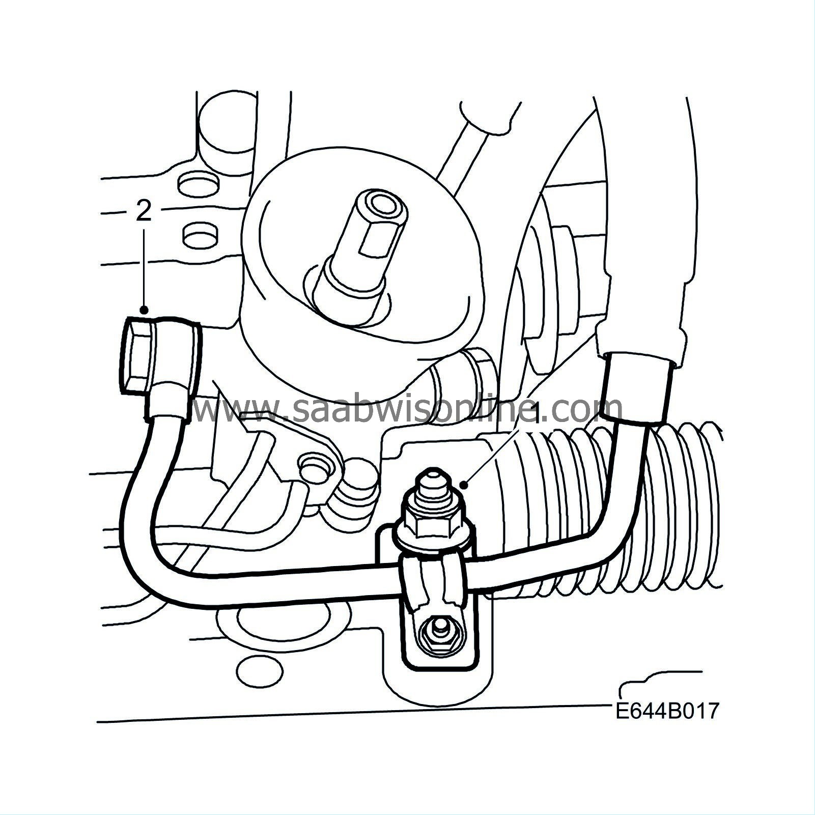
Fit a console on the right mounting for the steering gear.
Tightening torque 95 Nm (70 lbf ft)
|
|
2.
|
Fit the pipe in position, starting with the rear section.
RHD: The delivery line must be positioned to the right of the return line and behind the steering gear.
|
|
3.
|
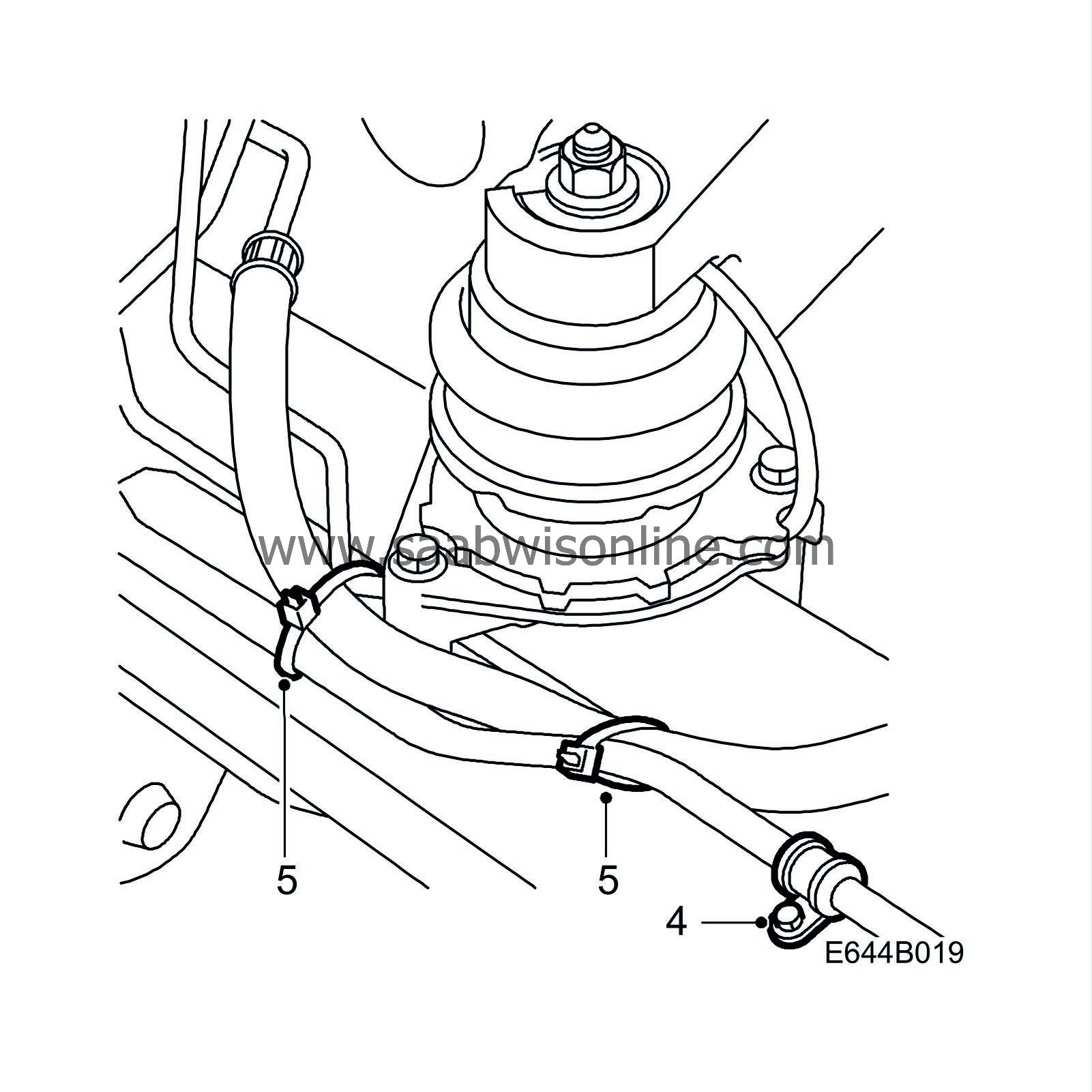
Remove the rear protection for the line and loosely fit the banjo nipple.
|
|
4.
|
Fit the rear clamp on the pipe and screw the clamp to the steering gear.
|
|
5.
|
LHD: Secure the return hose to the delivery line using 2 cable ties.
|
|
6.
|
Tighten the banjo nipple to the valve housing.
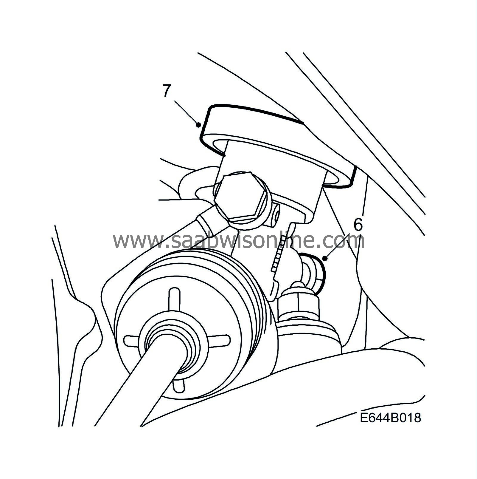
Tightening torque 30 Nm (22.2 lbf ft)
|
|
7.
|
Check that the seal between the steering gear and the body is positioned correctly.
|
|
8.
|
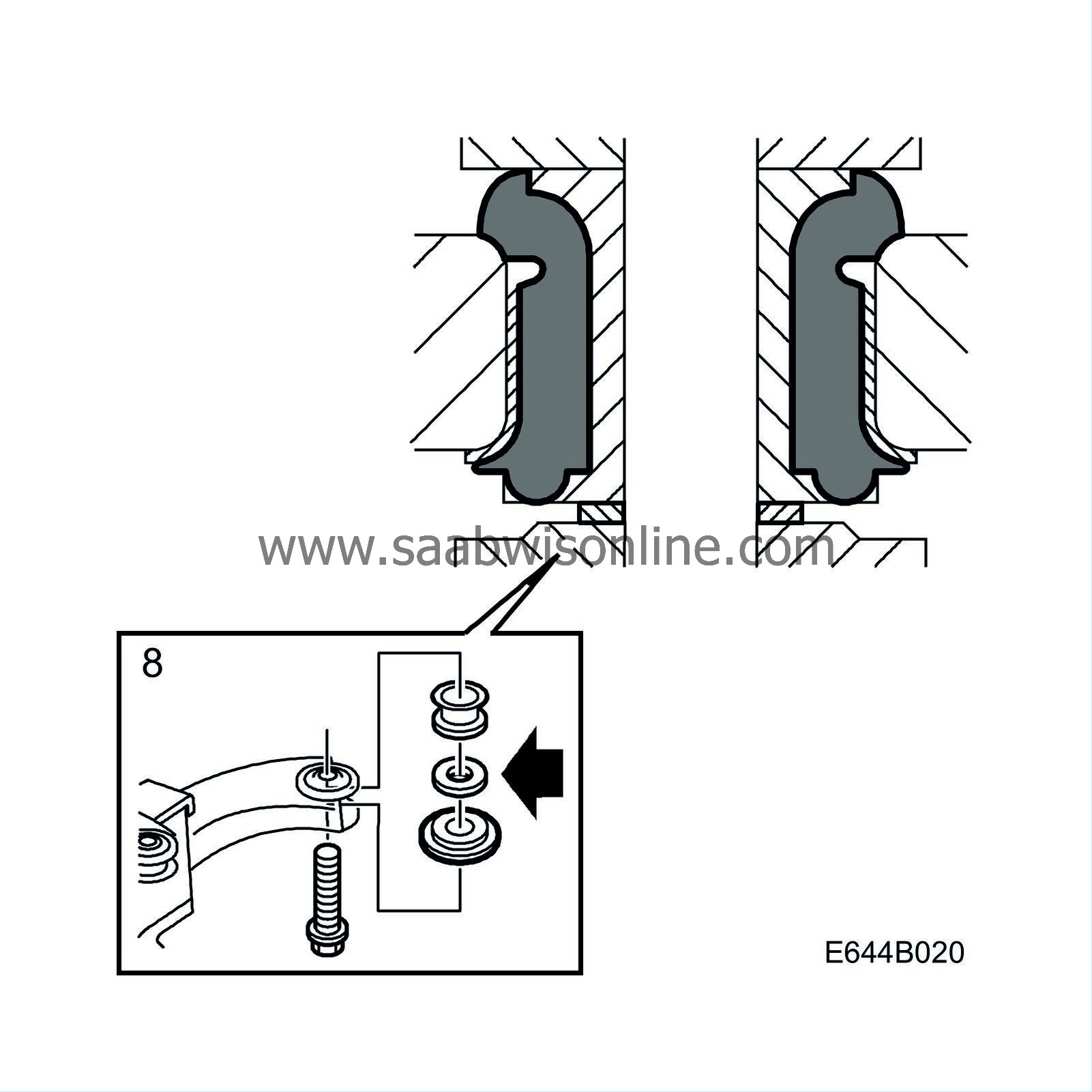
Raise the subframe and loosely fit the centre bolts. Make sure that the washers are fitted in the correct sequence; applies to cars with VIN up to and including W3050999.
|
|
9.
|
Fit and tighten the bolts for the reinforcement plates.
Tightening torque 65 Nm (48 lbf ft)
|
|
10.
|
Tighten the subframe mounting bolts.
Tightening torque 100 Nm + 45
°
(74 lbf ft)
|
|
11.
|
Fit the exhaust pipe joint and tighten the flange against the turbo.
|
|
12.
|
For cars where the front delivery line is also to be changed, continue on page 12.
|
|
13.
|
Remove the protection from the front section of the rear line and loosely connect the front pipe joint.
|
Important
|
|
Handle the O-rings with care.
|
|
|
|
|
14.
|
Fit the last clamps and plastic brackets between the hoses.
|
|
15.
|
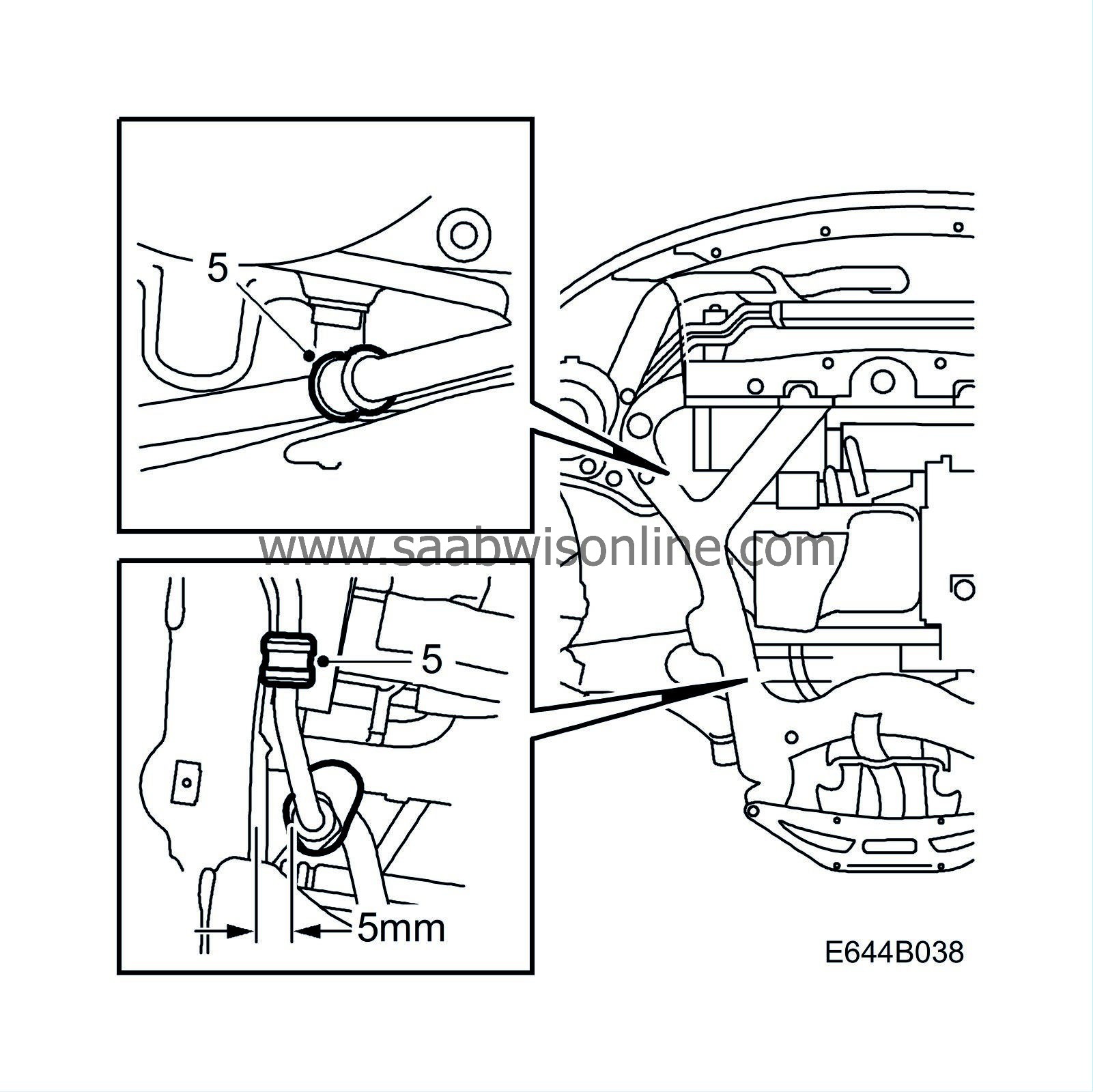
Tighten the delivery line joint. Check that the rear delivery line connection to the hose does not rest on the subframe, min. space 5 mm.
|
|
16.
|
Fit the right-hand cover.
|
|
18.
|
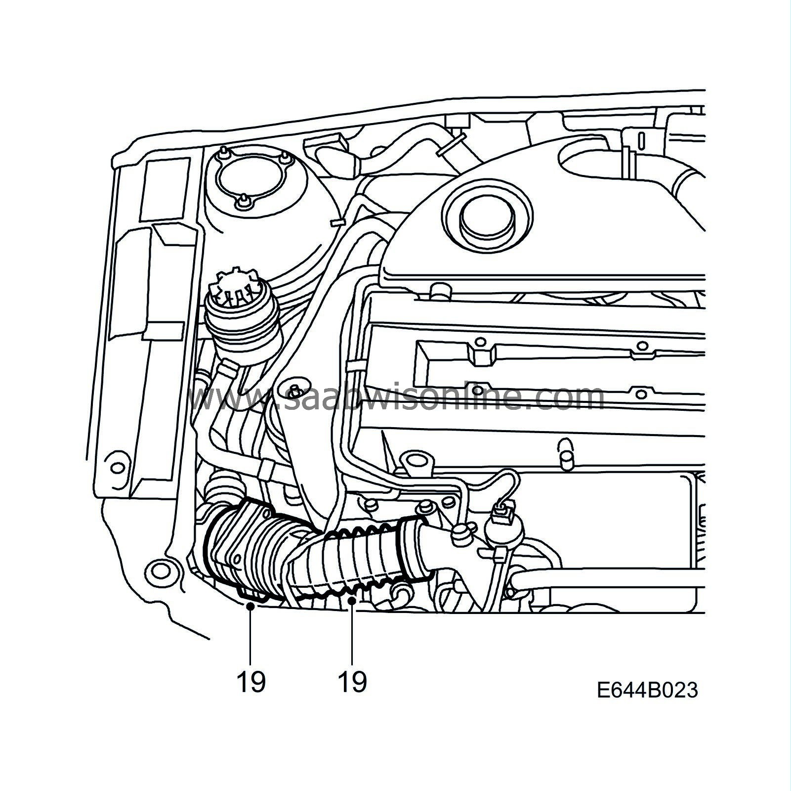
Remove the grille, right direction indicator and head lamp.
|
|
19.
|
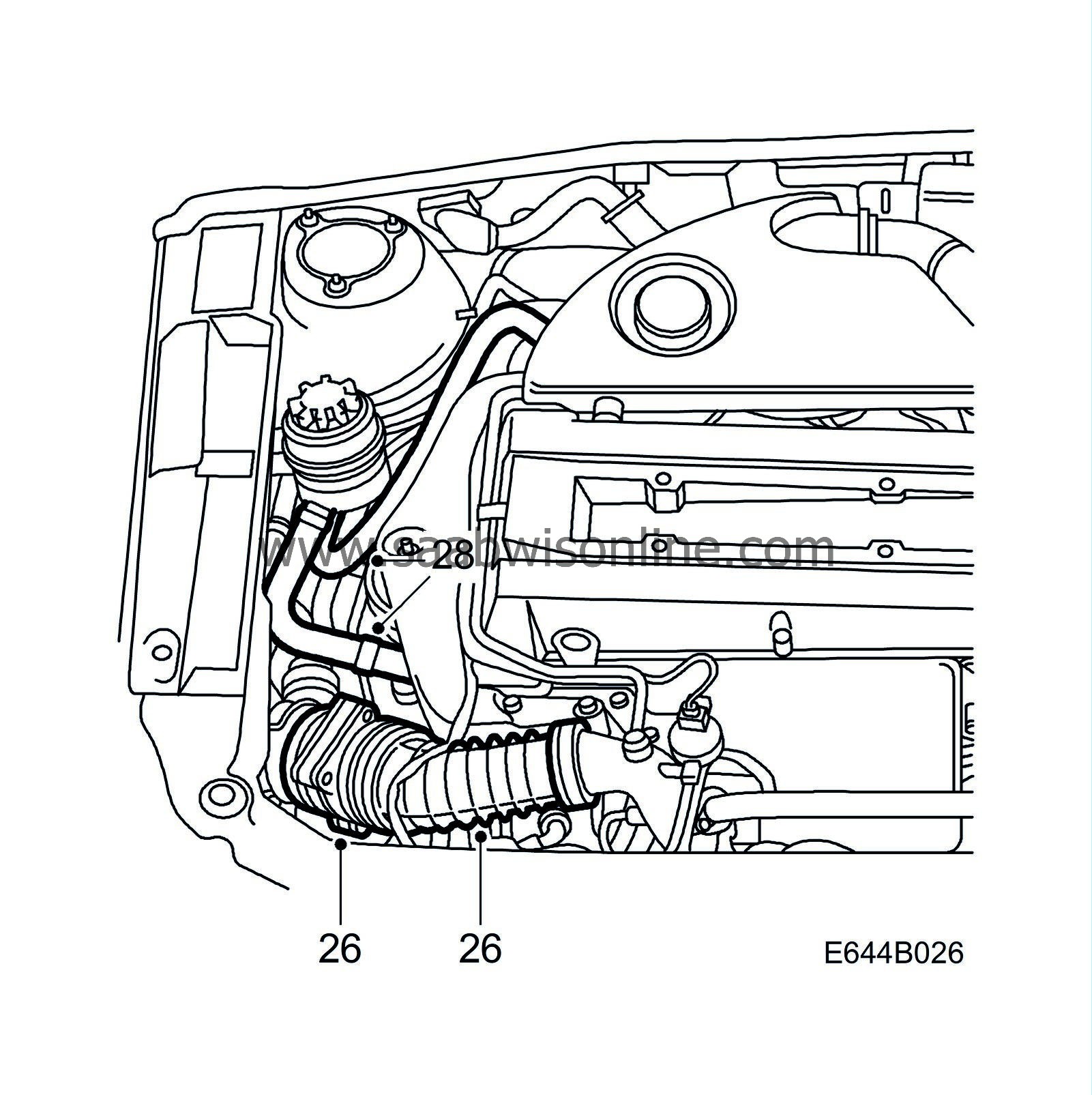
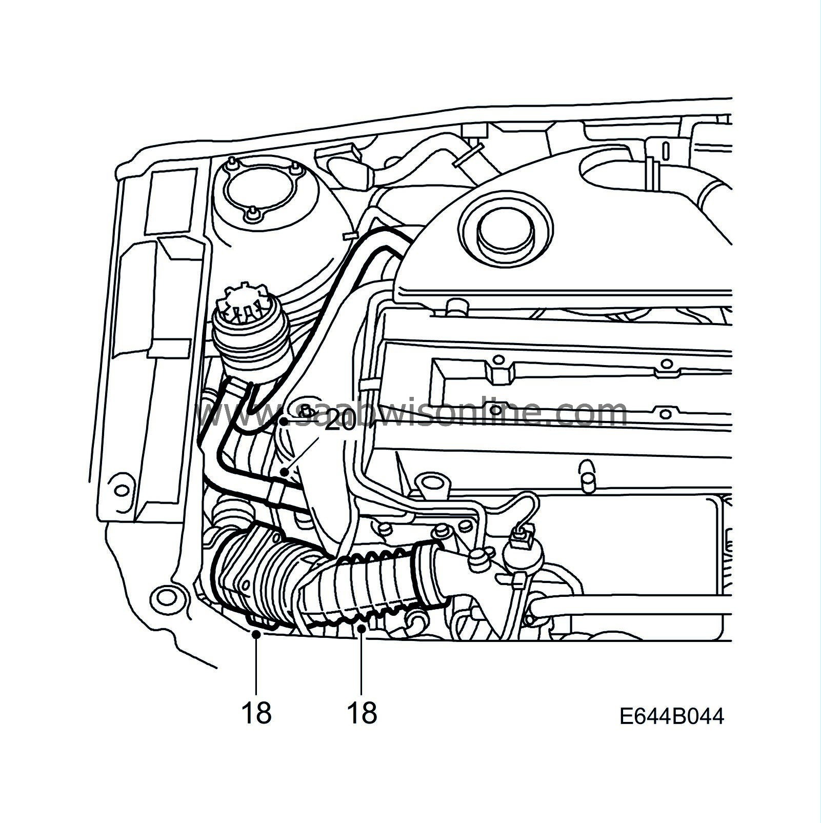
Loosen the hose clamp securing the intake hose with the mass air flow sensor and fold aside the hose.
|
|
20.
|
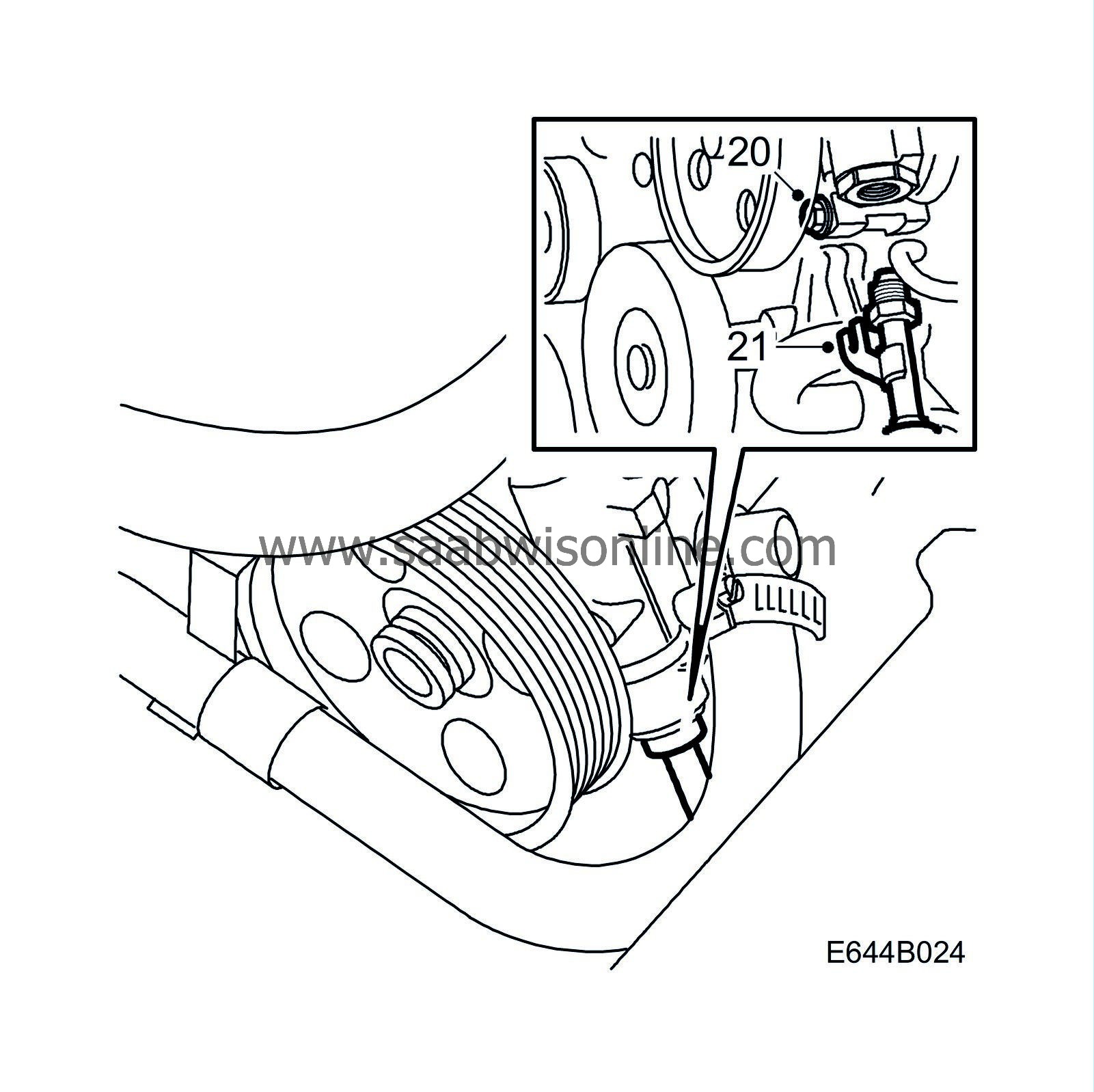
Relieve the belt tensioner using tool 83 95 254. Turn the servo pump belt pulley to access and undo the bolt on the console by the power steering pump for the front delivery line.
|
|
21.
|
Undo the connection between the delivery line and the servo pump, and carefully pull out the line towards the middle of the car.
|
|
22.
|
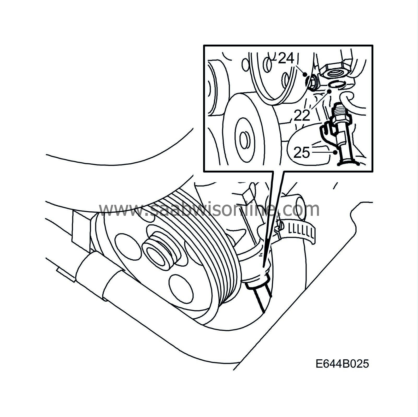
Remove the old O-ring and fit the new O-ring included in the kit. Lubricate the O-ring with power steering fluid.
|
|
23.
|
Position the delivery line console against the bolt between the washer and the pump, at the same time loosely fit the servo delivery line to the servo pump.
|
|
24.
|
Insert the bolt to the console before tightening the delivery line connection in the servo pump. Screw the delivery line into the servo pump as far as possible by hand, so as to guide the pipe to avoid deforming the console.
|
|
25.
|
Tighten the delivery line connection at the servo pump and the bolt for the console.
Tightening torque 24 Nm (17.8 lbf ft)
|
|
26.
|
Fit the intake hose on the intake manifold to the turbo.
|
|
27.
|
Fit the right-hand headlamp, direction indicator and the grille.
|
|
28.
|
Undo the pinch-off pliers on the suction and return hoses.
|
|
29.
|
Remove the lifting beam.
|
|
30.
|
Tighten the rear engine pad.
Tightening torque 50 Nm (37 lbf ft)
|
|
31.
|
Fit the engine cover.
|
|
32.
|
Make sure the front wheels are straight. Connect and tighten the steering column joint.

Tightening torque 30 Nm (22.2 lbf ft)
|
|
33.
|
Fill the power steering fluid reservoir with fluid and lift the front assembly so that the wheels are clear of the floor.
 Warning
|
|
If there is insufficient fluid in the system, the servo pump may be damaged if run longer than for 5 seconds.
|
|
|
|
|
|
|
|
34.
|
Start the engine and turn the steering wheel 2-3 times from full lock to full lock. Switch off the engine and check the fluid level.
 Warning
|
|
Never start the engine with the power steering fluid reservoir filler cap unscrewed. Fluid could spurt out of the reservoir.
|
|
|
|
|
|
|
|
35.
|
Start the engine and turn the steering wheel 2-3 times from full lock to full lock. Switch off the engine and check the fluid level.
|
|
36.
|
Make sure that there are no leaks in the system.
|
|
38.
|
Check the hose clamps on the suction hose between the power steering servo pump and the fluid reservoir.
Tightening torque 4 Nm (3 lbf ft)
|
Replacement of front delivery line
To remove
|
1.
|
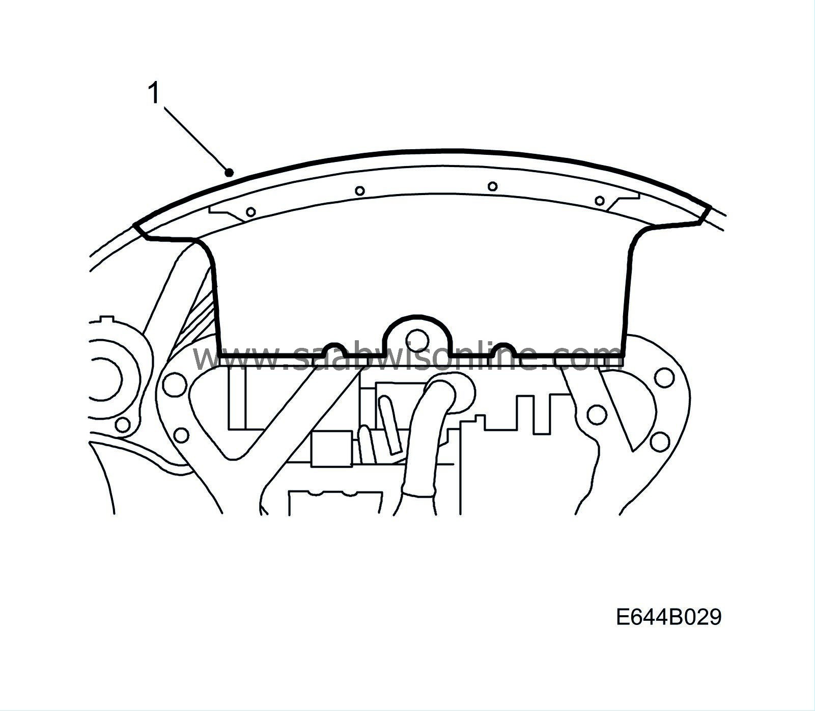
Remove the front cover under the bumper and lower the car.
|
|
2.
|
Lower the engine onto the rear engine cushions and remove the lifting beam.
Tighten the bolt securing the rear engine cushion to the engine mounting.
Tightening torque 50 Nm (37 lbf ft)
Fit the engine cover.
Remove the grille, right-hand direction indicator and headlamp. Undo the hose clamp securing the intake hose with the mass air flow sensor and fold aside the hose.
|
|
3.
|
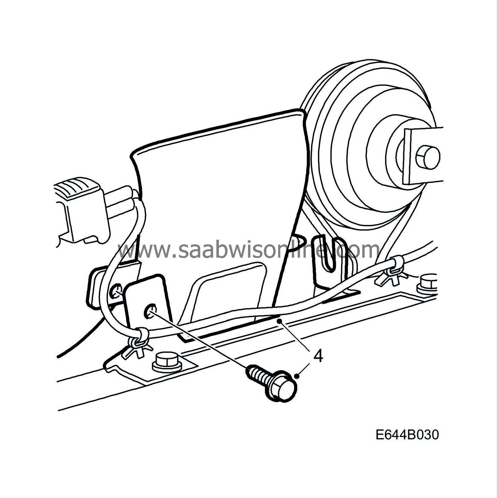
loosen the right horn slightly and turn the horn.
|
|
4.
|
Undo the screw for the air intake and remove the intake from its mounting.
|
|
5.
|
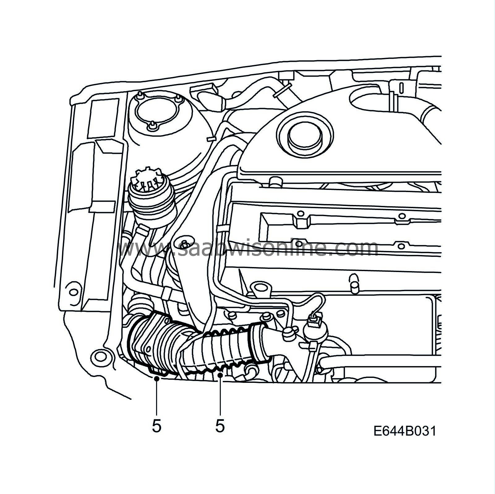
Loosen the hose clamp securing the intake hose with the mass air flow sensor and fold aside the hose.
|
|
6.
|
Relieve the belt tensioner using tool 83 95 254. Turn the servo pump belt pulley to access and undo the bolt on the console by the power steering pump for the front delivery line.
|
|
7.
|
Undo the connection between the delivery line and the servo pump, and pull out the line towards the middle of the car.
|
|
9.
|
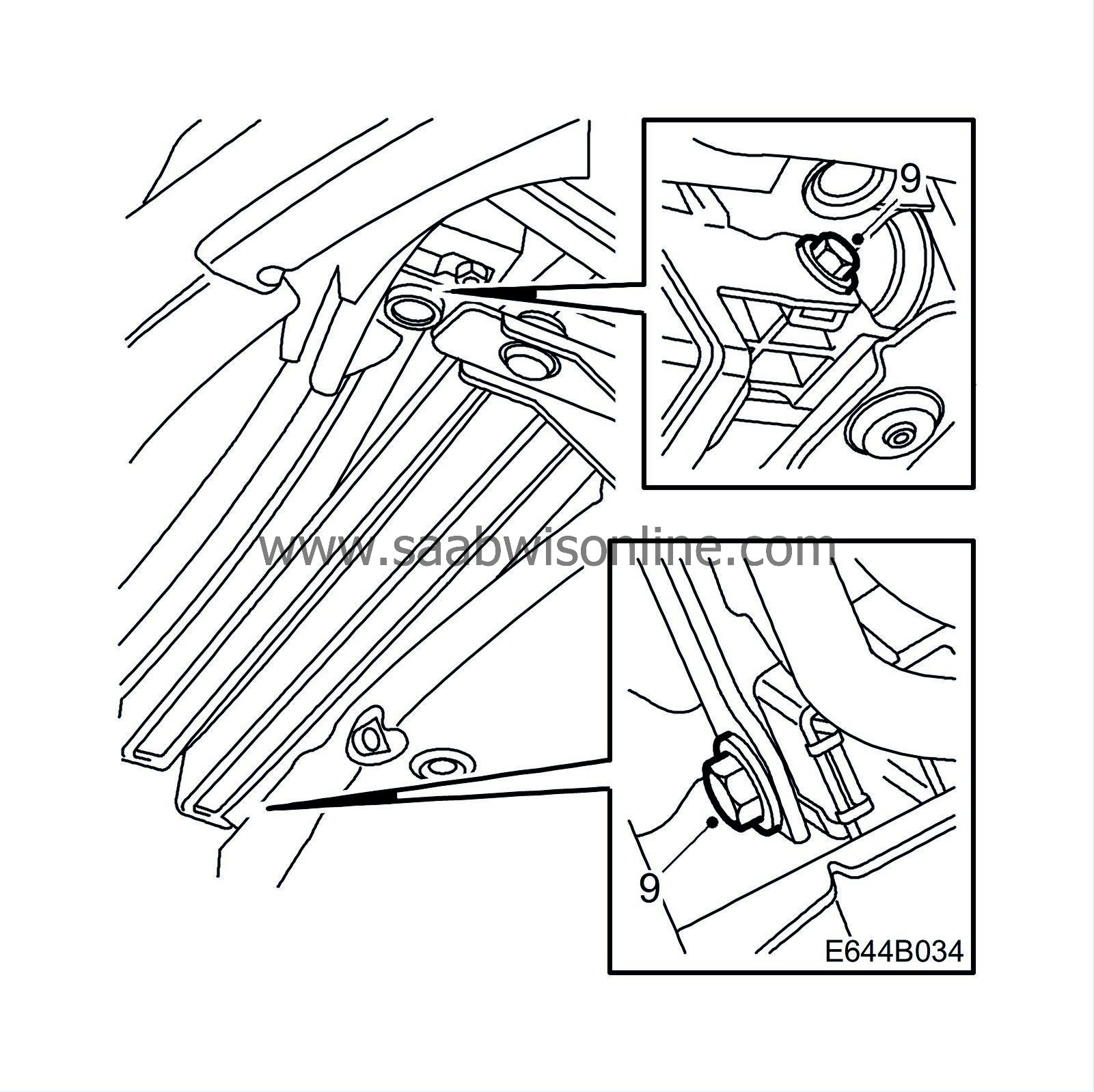
Undo the 2 bolts securing the engine oil cooler and leave the cooler suspended by its hoses.

|
|
10.
|
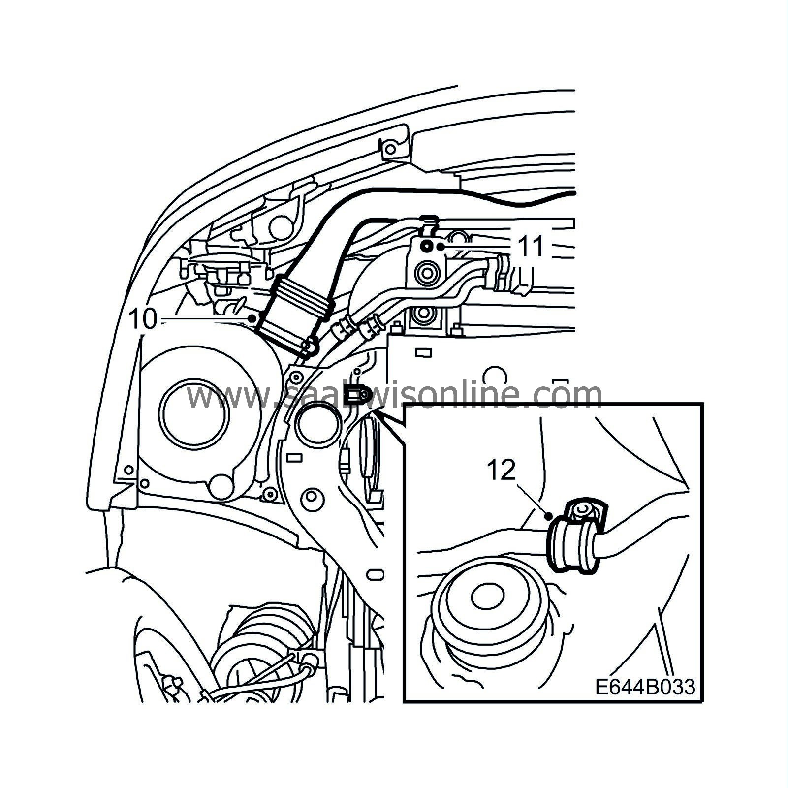
Loosen the hose clamp securing the hose for the air intake to the air filter holder and remove the air intake.
|
|
11.
|
Undo the nut that secures the cooling loop to the cooler mounting.
|
|
12.
|
Undo the clamp on the front delivery line and remove it from the retaining screws. If there is a washer under the clamp, remove it, it is not to be refitted.
|
|
13.
|
Angle the cooling loop on the front delivery line downwards so that the entire front delivery line can be removed.
|
Important
|
|
Scrupulous cleanliness must always be observed when carrying out any work involving hydraulic components.
|
|
|
|
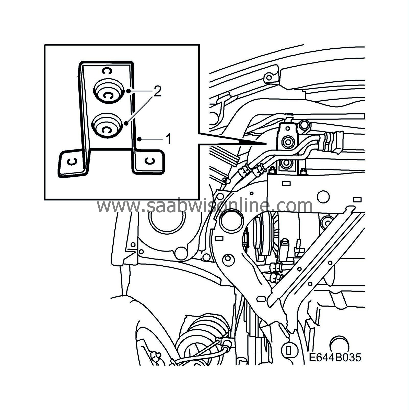
Cars with VIN W3050321-W3050848
|
1.
|
Remove the console for the cooler mounting.
|
Important
|
|
Bear in mind that the cooler is spring loaded, from above.
|
|
|
|
|
2.
|
Remove the rubber bushes from the console and transfer them to the new console included in the kit.
|
|
3.
|
Fit the console on the subframe and tighten the nuts.
Tightening torque 20 Nm (14.8 lbf ft)
|
To fit
|
1.
|
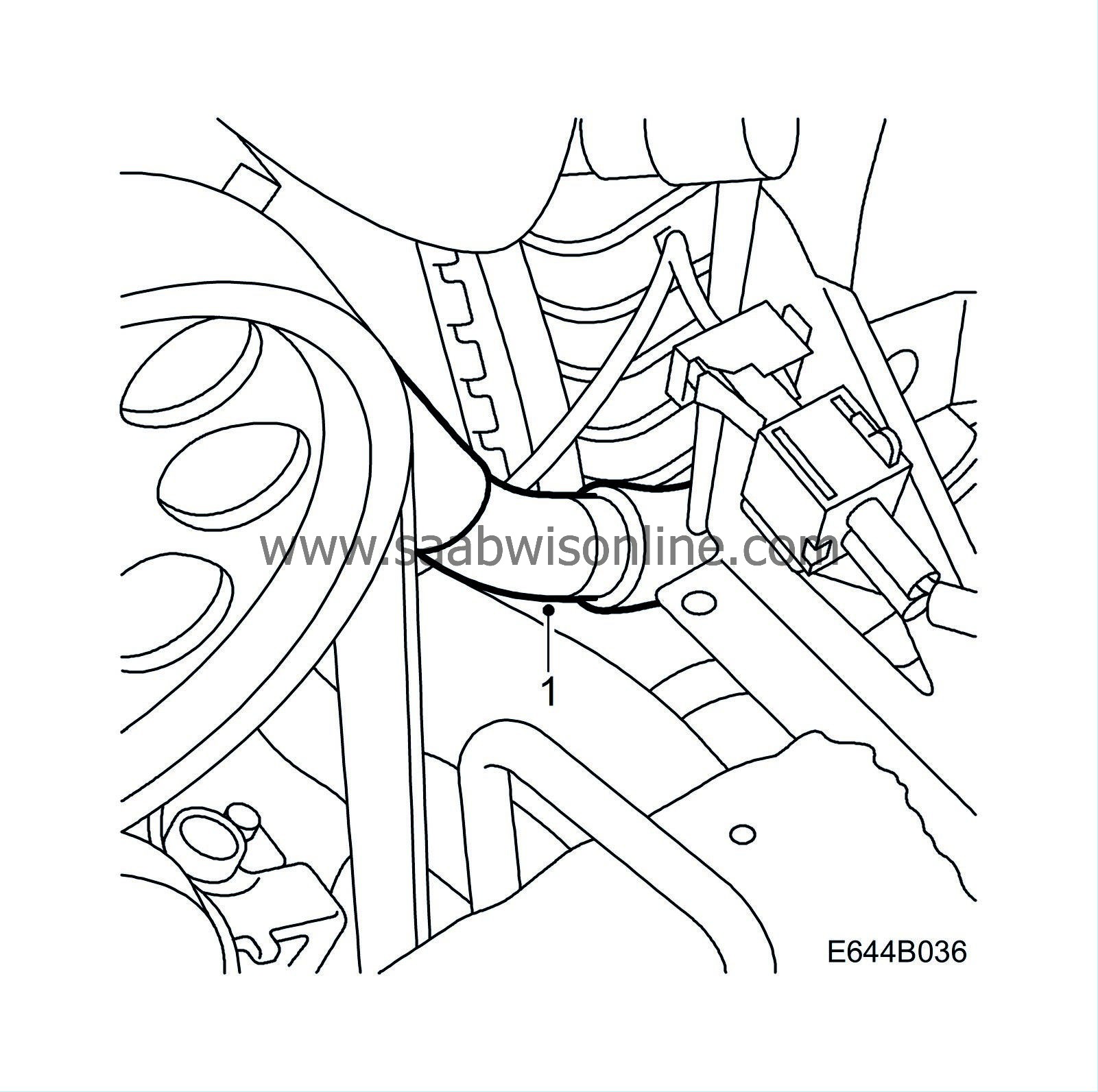
Fit the front delivery line. The line must be inserted between the radiator member and the radiator behind the cable for the A/C compressor, if one is fitted.
|
Important
|
|
The A/C compressor cable catches easily in the delivery line console.
|
|
|
|
|
2.
|
Remove the protection on the front and rear lines, join the lines and tighten as tight as possible by hand.
|
|
3.
|
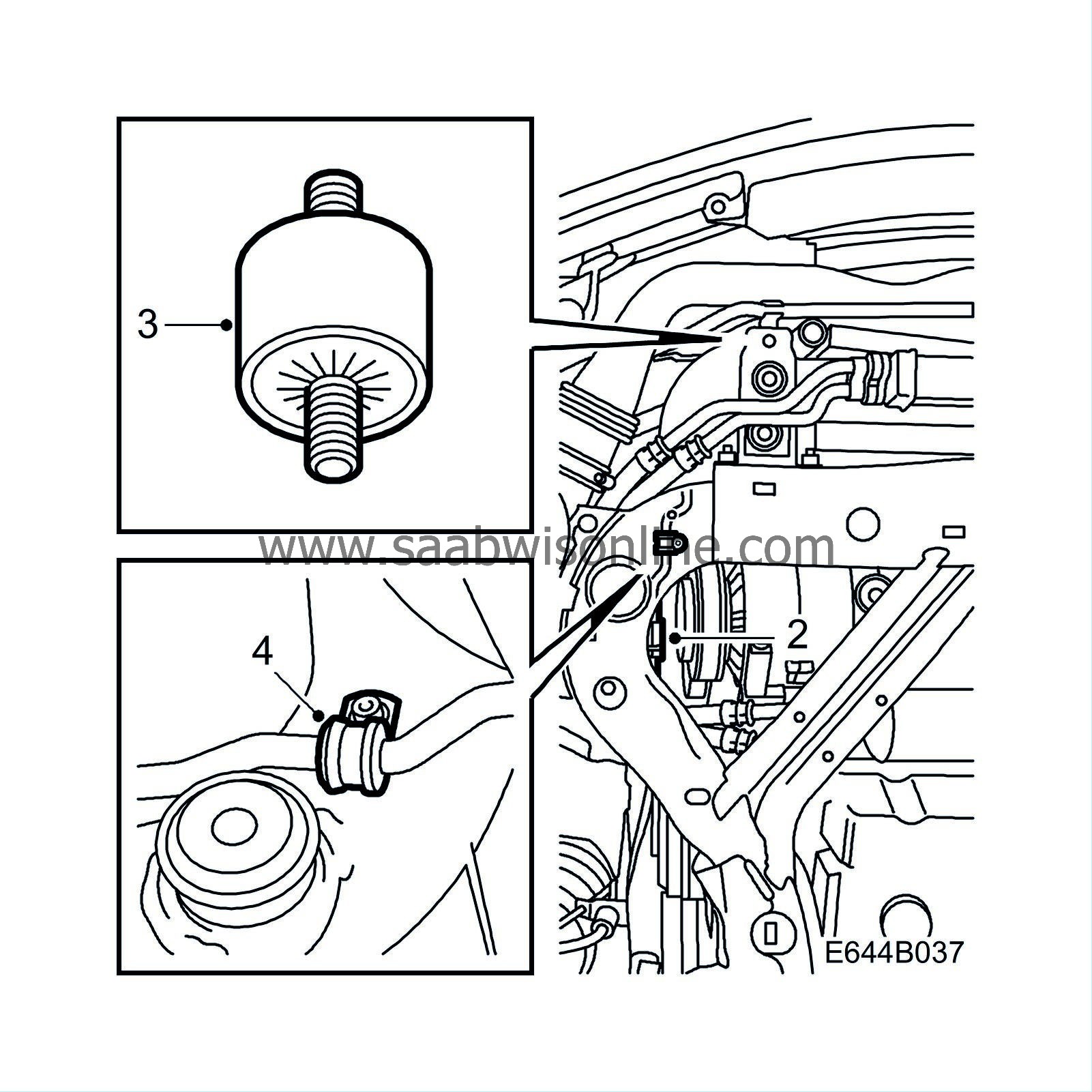
Fit the rubber suspension on the mounting for the cooler unit. Then fit the delivery line on the rubber suspension.
|
|
4.
|
Fit the clamp on the line and tighten the line and clamp to the subframe with the retaining screw.
|
|
5.
|
Tighten the two clamps on the rear delivery line, starting with the front clamp. Check that the rear delivery line connection to the hose does not rest on the subframe, min. space 5 mm.
|
|
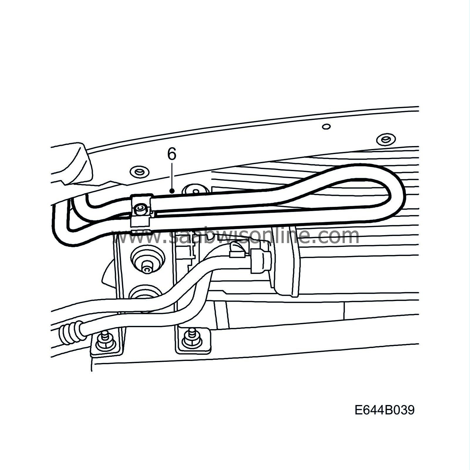
6.
|
Check that the cooling loop is horizontal and tighten the front line together with the rear line.
|
|
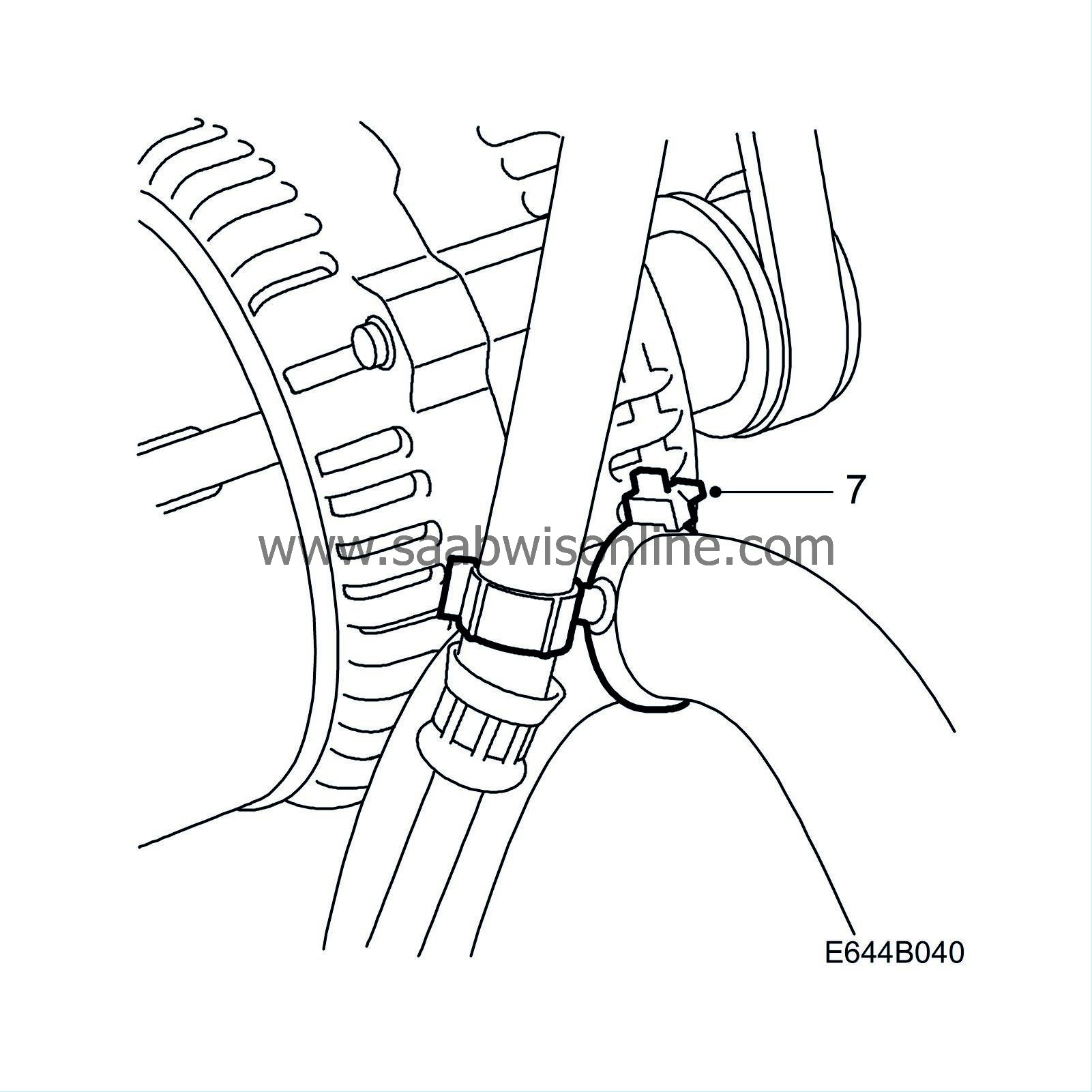
7.
|
Fit a cable tie with bracket between the delivery hose and return hose.
|
|
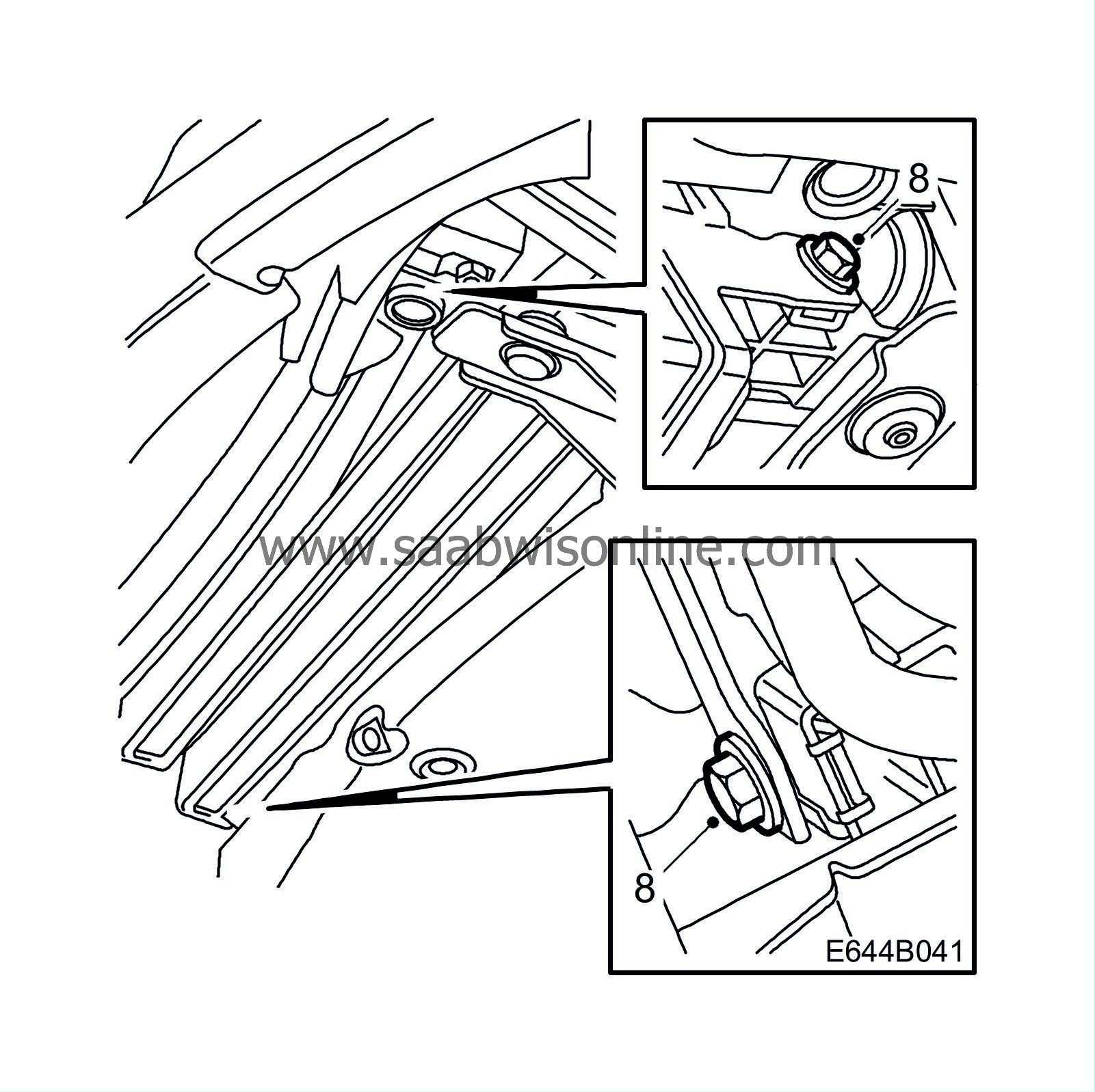
8.
|
Fit the engine oil cooler with 2 bolts.
|
|
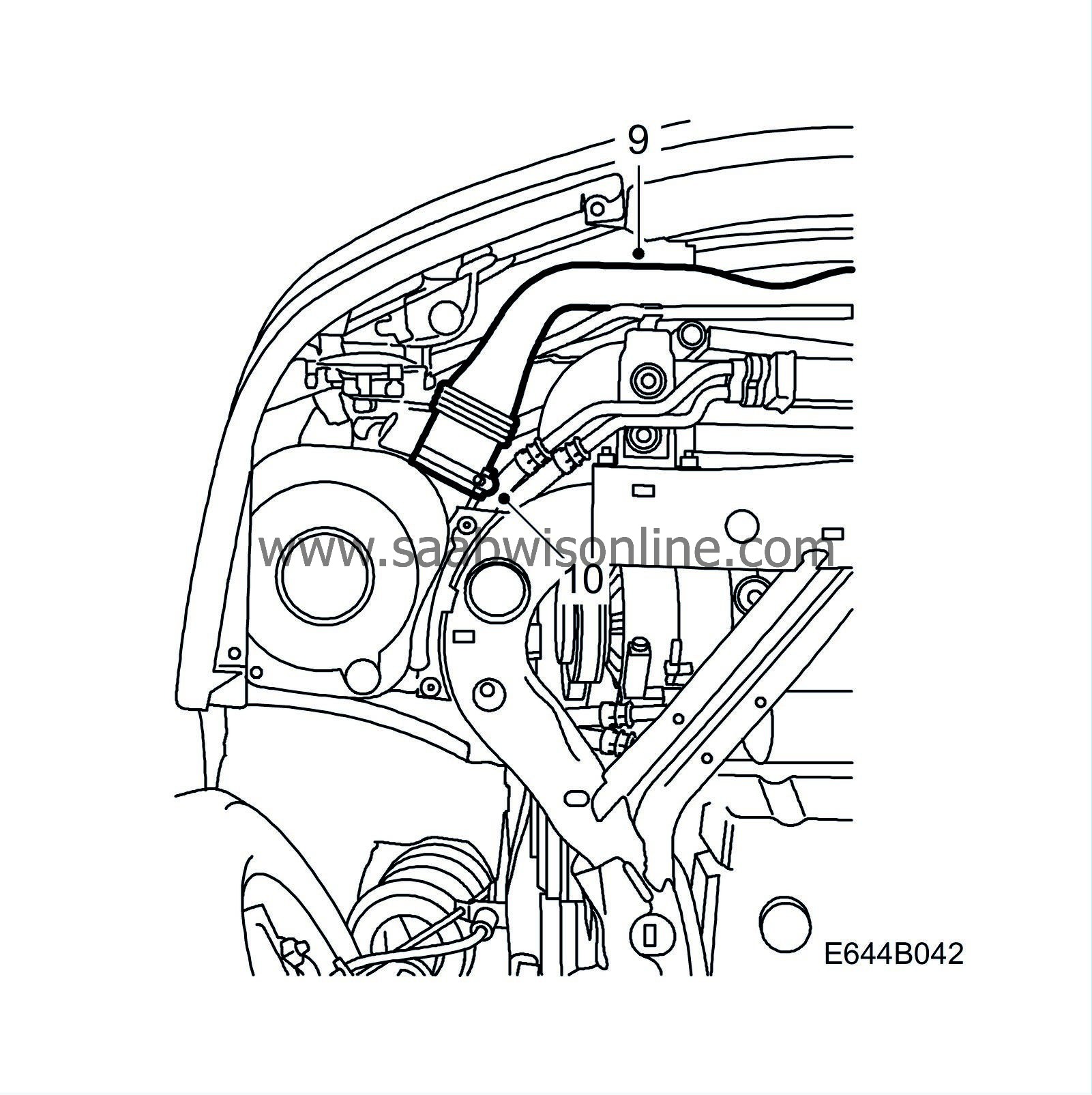
9.
|
Refit the air intake to the air filter housing and turn up the air intake in front of the radiator.
|
|
10.
|
Tighten the hose clamp for the lower mounting of the air intake to the air filter housing.
|
|
11.
|
Wipe the subframe clean of any spilt oil.
|
|
12.
|
Wipe off any oil on the air deflectors and fit the deflectors.
|
|
14.
|
Lift and fit the air intake and tighten the bolt. Tighten the right horn.
|
|
15.
|
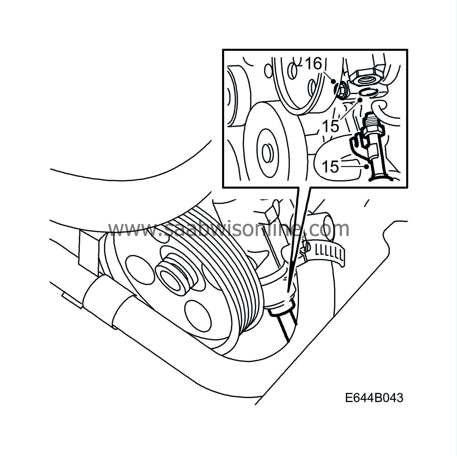
Position the delivery line console against the bolt between the washer and the pump, at the same time loosely fitting the servo delivery line to the servo pump. Lubricate the O-ring with power steering fluid.
|
|
16.
|
Insert the bolt to the console before tightening the delivery line connection in the servo pump. Screw the delivery line into the servo pump as far as possible by hand, so as to guide the pipe to avoid deforming the console.
|
|
17.
|
Tighten the delivery line connection at the servo pump and the bolt for the console.
|
|
18.
|
Fit the intake hose on the intake manifold to the turbo.
|
|
19.
|
Fit the right-hand headlamp, direction indicator and the grille.
|
Note
|
|
Make sure that the headlamp drain hose does not get pinched.
|
|
|
20.
|
Undo the pinch-off pliers on the suction and return hoses.
|
|
21.
|
Make sure the front wheels are straight. Connect and tighten the steering column joint.
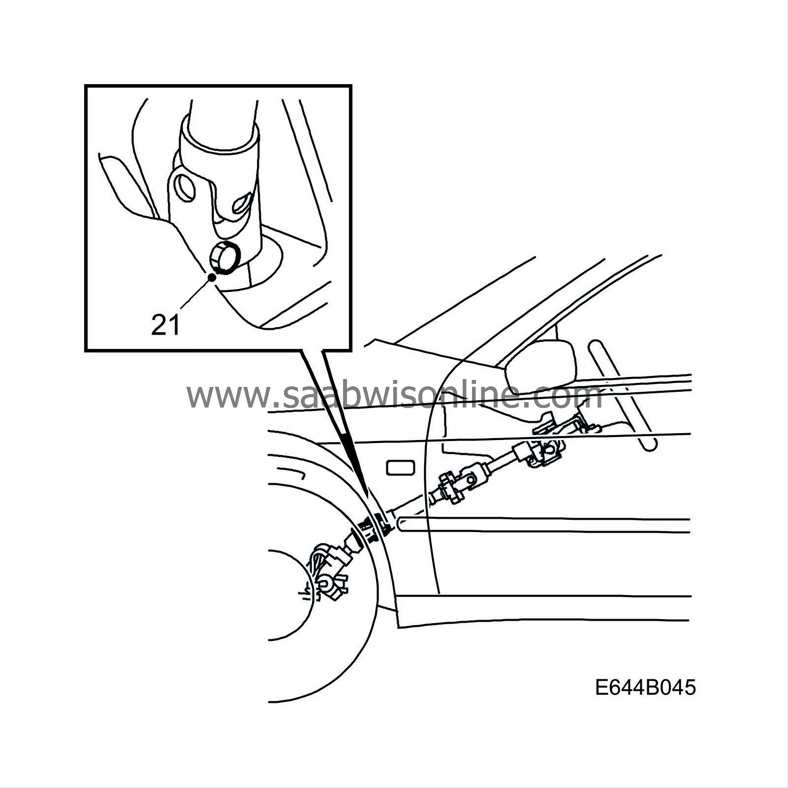
Tightening torque 30 Nm (22.2 lbf ft)
|
|
22.
|
Fill the power steering fluid reservoir with fluid and lift the front assembly so that the wheels are clear of the floor.
 Warning
|
|
If there is insufficient fluid in the system, the servo pump may be damaged if run longer than for 5 seconds.
|
|
|
|
|
|
|
|
23.
|
Start the engine and turn the steering wheel 2-3 times from full lock to full lock. Switch off the engine and check the fluid level.
 Warning
|
|
Never start the engine with the power steering fluid reservoir filler cap unscrewed. Fluid could spurt out of the reservoir.
|
|
|
|
|
|
|
|
24.
|
Start the engine and turn the steering wheel 2-3 times from full lock to full lock. Switch off the engine and check the fluid level.
|
|
25.
|
Make sure that there are no leaks in the system.
|
|
27.
|
Check tighten the hose clamps on the suction hose between the power steering servo pump and the fluid reservoir.
Tightening torque 4 Nm (3 lbf ft)
|
|
Marking the modification identity plate
|
Following the completion of the work, box A2 on the modification identity plate must be marked. If the procedure was carried out by the importer, mark the box with the number “7”, and if carried out by the dealer, with the number “8”.
|
Warranty/Time Information
|
See separate information.



 Warning

