Power train
| Power train |
| Removing the power train |
|
|||||||
| 1. |
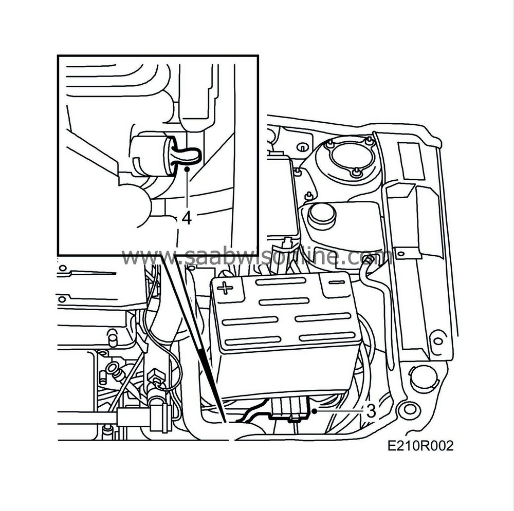
Lay out wing covers, remove the covers over the battery and intake manifold and remove the battery and battery tray. Open the expansion tank cap.
|
|
| 2. |
(aut.) Withdraw the breather hose which sticks up under the main fuse box.
|
|
| 4. |
Open the drain plug for the coolant.
|
||||||||||||
| 5. |
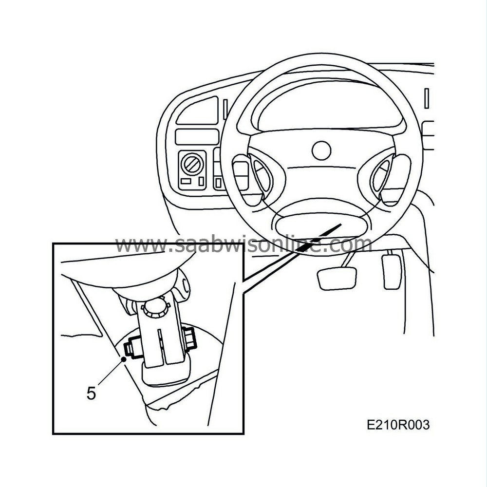
Turn the front wheels to the straight ahead position and secure the steering wheel in this position. Undo the steering column locking bolt and move the steering column upwards.
|
|
| 6. |
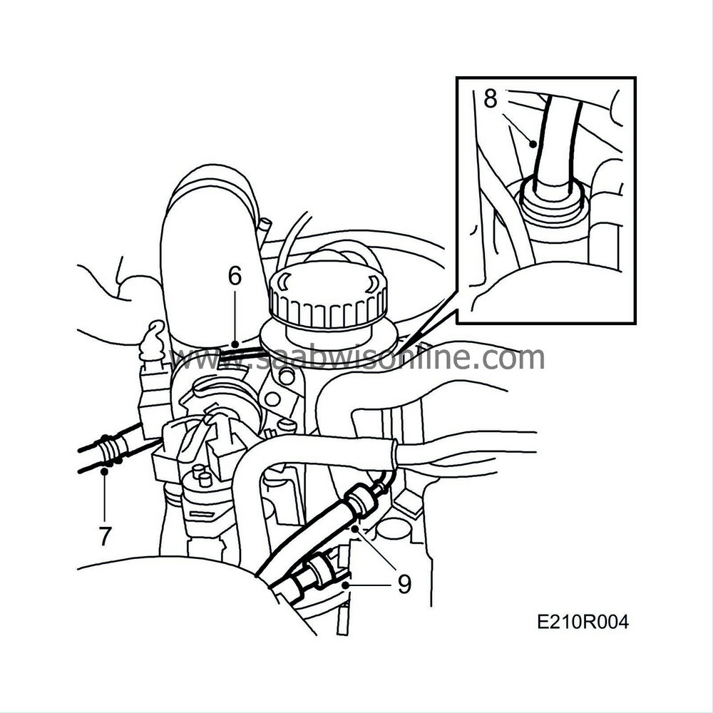
Disconnect the throttle cable and move it aside.
|
|
| 7. |
Disconnect the EVAP canister purge valve's vacuum hose from the intake manifold.
|
|
| 8. |
Disconnect the brake servo vacuum hose by pressing the red sleeve downwards and pulling the hose upwards.
|
|
| 9. |
Disconnect the fuel connectors with
83 95 261 Tools, Fuel line
and plug them.
|
|||||||
| 10. |
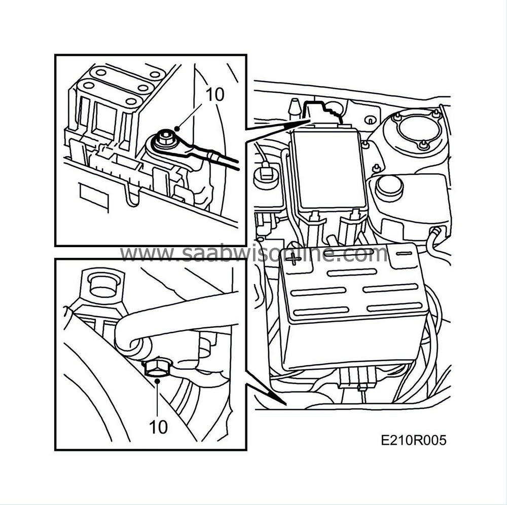
Disconnect the positive cable at the distribution terminal and the negative cable at the gearbox.
|
|
| 11. |
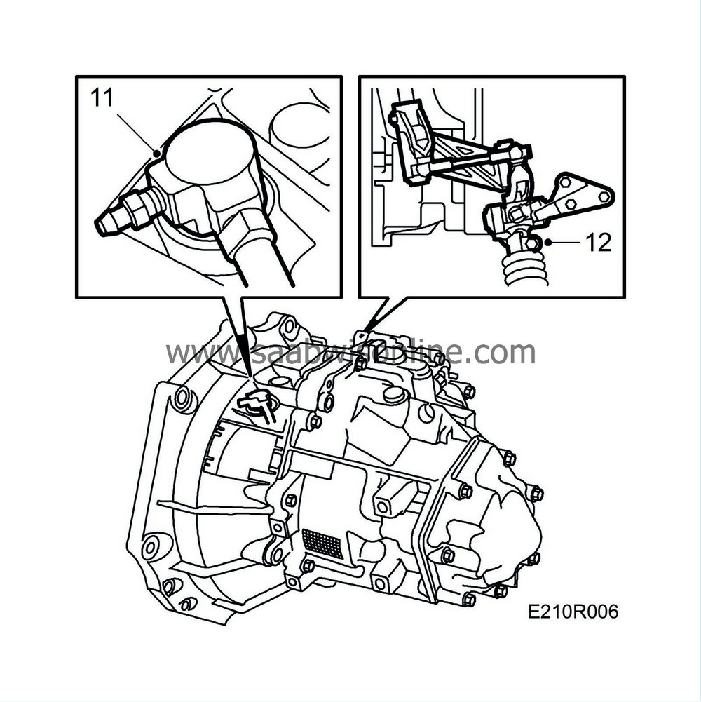
(man.) Disconnect the clutch slave cylinder's hose and plug the hose.
|
|
| 12. |
(man.) Engage 4th gear, remove the selector rod and engage 3rd gear.
|
|
| 13. |
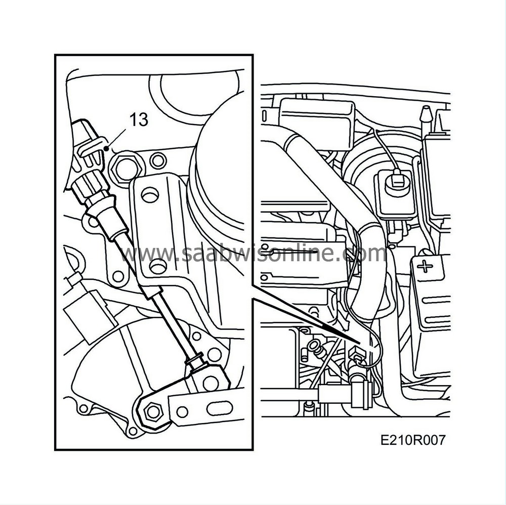
(aut.) Disconnect the selector lever cable and bend it aside against the bulkhead.
|
|
| 14. |
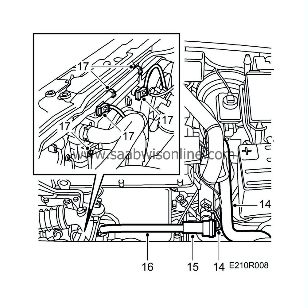
Disconnect the upper radiator hose and remove the bypass valve's vacuum hose.
|
|
| 15. |
Remove the hose between the pipe connected to the throttle body and the charge air cooler and unplug the temperature sensor's connector.
|
|
| 16. |
Remove the bypass valve with intake manifold and plug same.
|
|
| 17. |
Unplug the connector for the radiator fan or fans. Remove the fan cowling retaining bolts, disconnect the upper radiator hose at the top and the pipe connected to the oil cooler (aut.).
Carefully lift out the fan cowl. |
|
| 18. |
Remove the grille.
|
|
| 19. |
Disconnect the hose between the turbocharger and charge air cooler and plug same.

|
|
| 20. |
Remove the mass air flow sensor with rubber gaiter and unplug its connector.
|
|
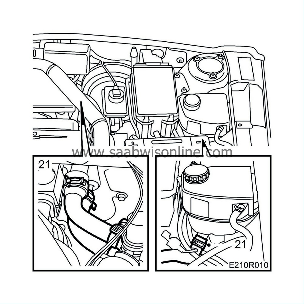
| 22. |
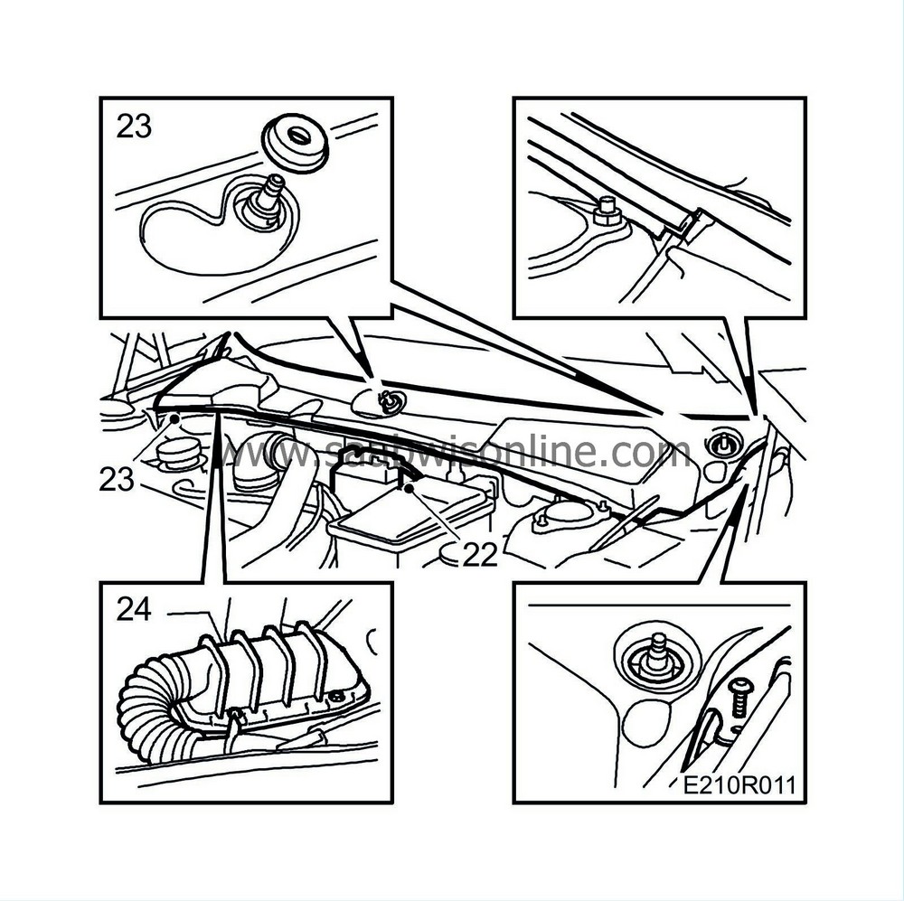
Remove the bracket with the connector for the engine wiring harness and the wiring harness mountings from the bulkhead. Unhook it and lay it on the engine.
|
|
| 23. |
Remove the wiper arms and the cover over the wiper assembly. Use puller
Puller
85 80 144.
|
|||||||
| 24. |
Undo the nuts securing the control module connector. Unplug the connector and place it on the engine.
|
|
| 25. |
Remove the hub nuts on both sides and raise the car.
|
|
| 26. |
Remove the front wheels.
|
|
| 27. |
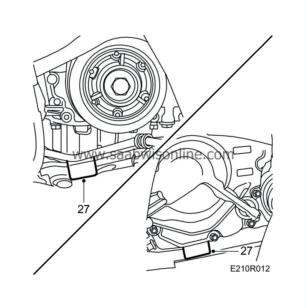
Drive in
Wedges
83 95 238 between the gearbox and subframe and between the oil sump and subframe.
|
|
| 28. |
Raise the car.
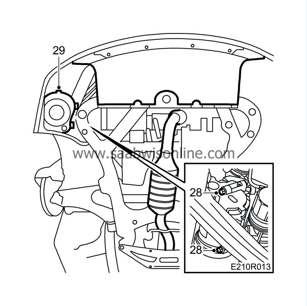
Remove the A/C compressor's retaining bolts. |
|
| 29. |
Remove the retaining nuts and air hose from the air filter housing.
|
|
| 30. |
Lower the car to the floor.
|
|
| 31. |
Suspend the condenser cooler, charge air cooler and A/C compressor from the radiator member with
Straps
83 95 212. The engine oil cooler is dismantled with the engine and fastened to the subframe with, for instance, cable ties.
|
|
| 32. |
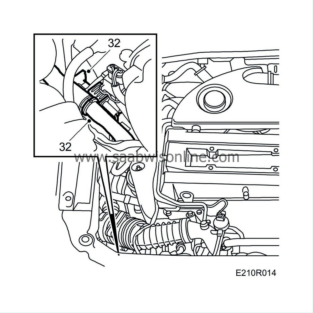
Unplug the A/C compressor connector and undo the quick-release coupling on the vacuum hose connected to the wastegate.
|
|
| 33. |
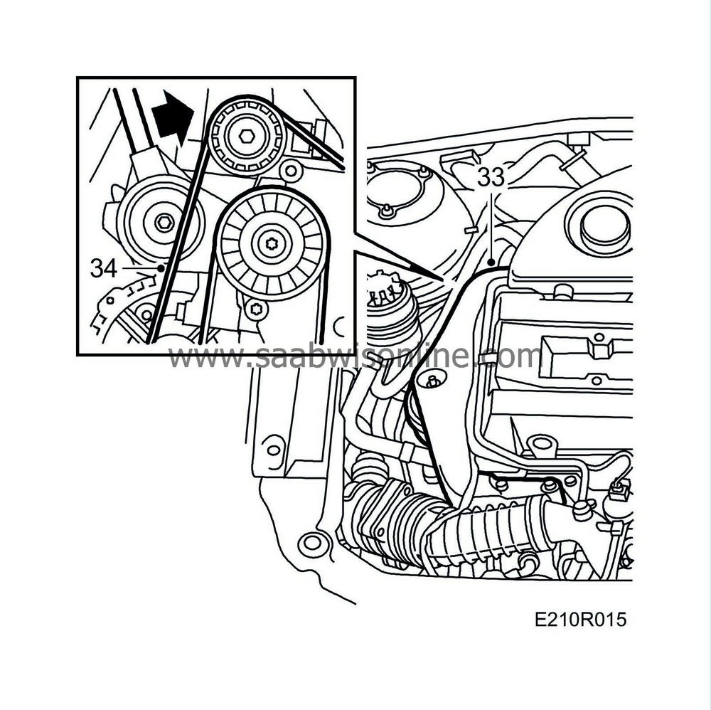
Remove the right-hand engine mounting complete with yoke.
|
|
| 34. |
Relieve the pressure on the belt tensioner using a ratchet handle and lift off the multigroove belt.
|
|
| 35. |
Remove the left-hand engine mounting's retaining nuts.

|
|
| 36. |
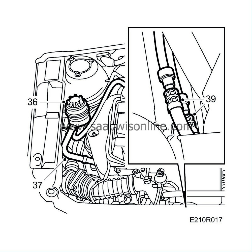
Remove the power steering fluid reservoir with hoses and place it on the engine.
|
|
| 37. |
Pinch off the hose between the steering servo and reservoir.
|
|
| 38. |
Remove the sheet metal mounting on the pipe to the steering servo. Slightly loosen the steering servo hose so that it becomes moveable.
|
|
| 39. |
(aut.) Unplug the quick-release couplings to the gearbox oil cooler and plug them. Use
83 95 261 Tools, fuel line
. Mark the hoses to tell them apart.
|
|
| 40. |
Raise the car higher.
|
|
| 41. |
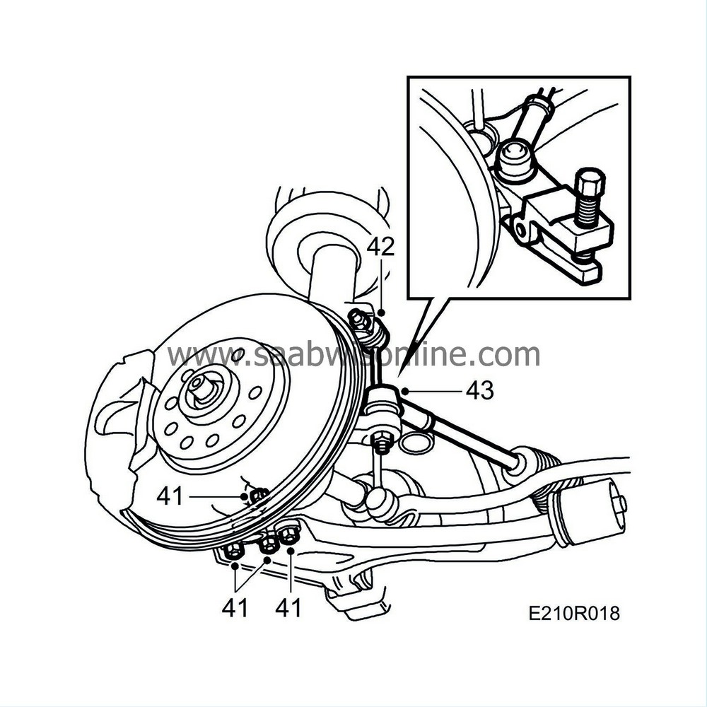
Remove the three steering swivel joint retaining nuts on both sides.
|
|
| 42. |
Undo the nuts securing the anti-roll bar supports to the suspension strut.
|
|
| 43. |
Undo the two outer track-rod ends. Use
Puller, ball joint
89 96 696.
|
|
| 44. |
Carefully tap the drive shafts out of the hubs.
|
|
| 45. |
Remove the oil cooler and suspend it from the front of the engine frame.

|
|
| 46. |
Separate the exhaust pipe behind the catalytic converter and remove the temperature sensor.
|
|
| 47. |
Run
Lifting trolley
83 94 739 with assembly fixture 83 95 196 under the car. Align the fixture with adjusting feet 83 95 170 under the subframe with the locating studs at front left and rear right.
|
|
| 48. |
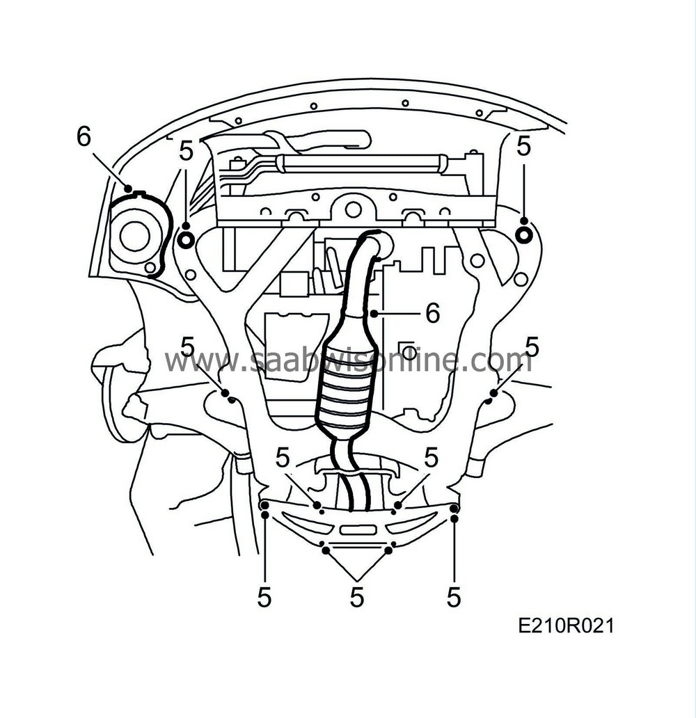
Remove the 10 subframe and supporting plate retaining bolts.
From chassis number W3050999, the inner sleeve in the subframe bushings has been made 38 mm long instead of previously 35 mm. If the bushing is 35 mm, a 3 mm spacer must be fitted between the bushing and washer.
|
|||||||||
| 49. |
Lower the lifting trolley approx. 25 cm and thus also the subframe and power train. Make sure that the swivel joints release and lift out the drive shafts. Unhook the hose for the engine oil cooler from its bracket on the subframe.
|
|
| 50. |
Pull the trolley as far back as possible to provide room for the A/C compressor and lower carefully.
|
|
| 51. |
Then lower the power train complete with subframe, steering gear and front exhaust pipe.
|
|
| Fitting the power train |
|
|||||||
| 1. |
Run the lifting trolley with power train under the raised car.
|
|
| 2. |
Lower the car with care and raise the lifting table.
|
|
| 3. |
Raise the engine with the lifting trolley, fitting the locating studs in their positions at front left and rear right. Make sure that the steering gear fits in place in the bulkhead.
|
|
| 4. |
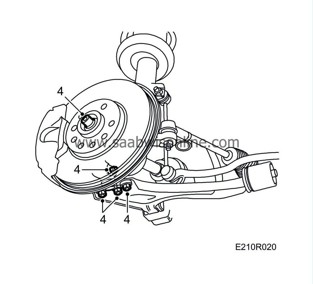
Fit the drive shafts and screw on the three nuts securing the steering swivel joints.
Tightening torque: 30 Nm (22.5 lbf ft) +90 |
|
| 6. |
Fit the exhaust pipe, temperature sensor and air cleaner in the subframe.
|
|
| 7. |
Fit the track rod ends and anti-roll bar support to the suspension strut. Hold with a open wrench or hold the hexagonal pin with a socket.
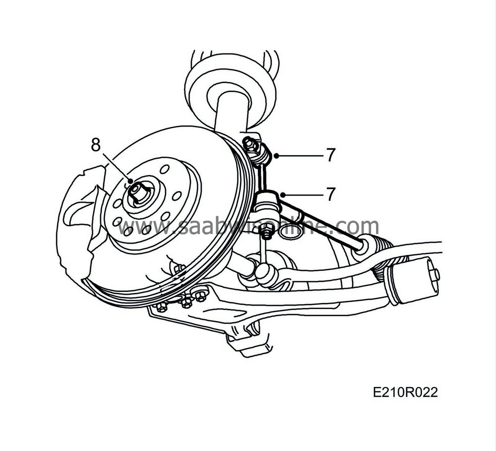
Tightening torque: 84 Nm (62 lbf ft) Tightening torque, nut with steel lock: 95 Nm (66 lbf ft) |
|
| 8. |
Fit the hub nuts but do not tighten them.
|
|
| 9. |
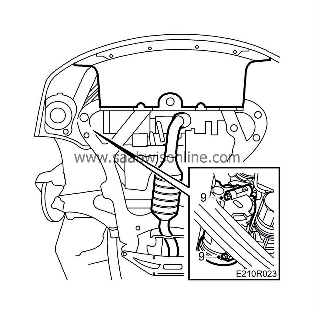
Fit the A/C-compressor and air filter housing retaining nuts and hose.
|
|
| 10. |
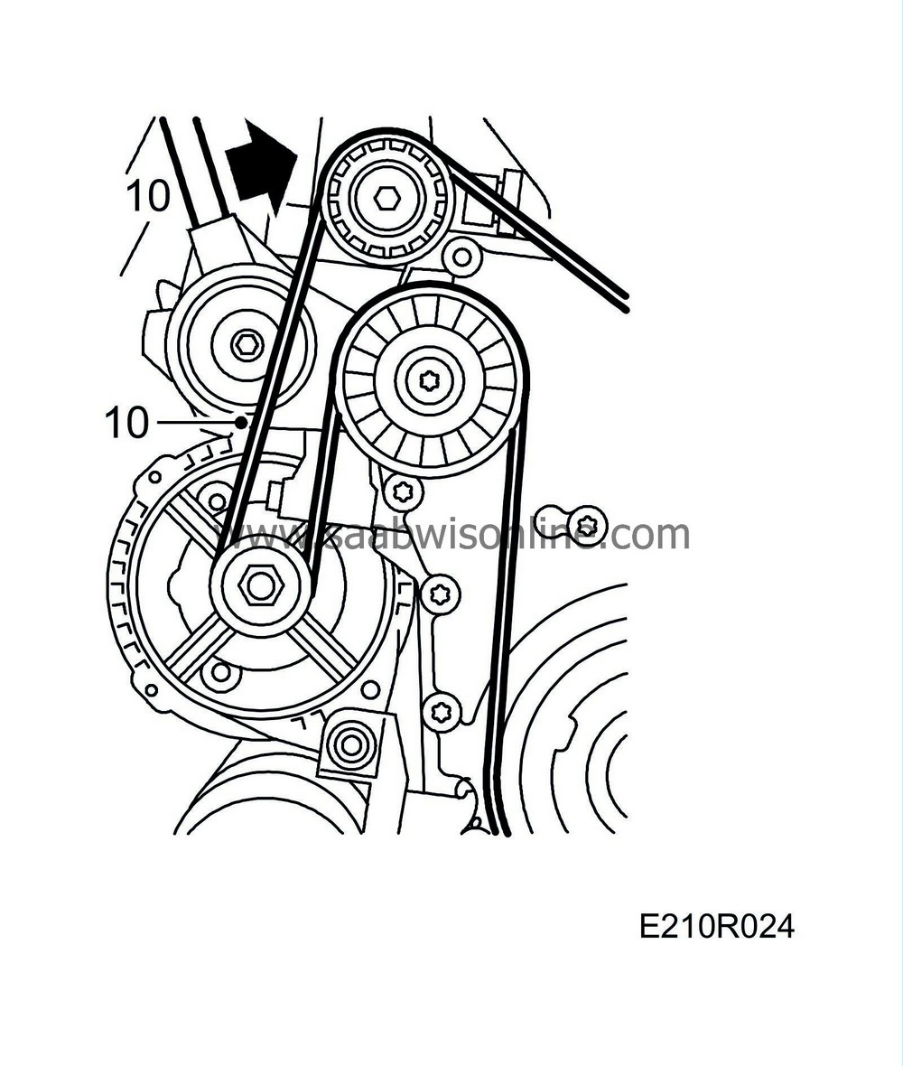
Lower the car to the floor. Fit the strap and tighten it.
|
|
| 11. |
Set the steering gear in the straight-ahead position and mount the steering column in the cabin.
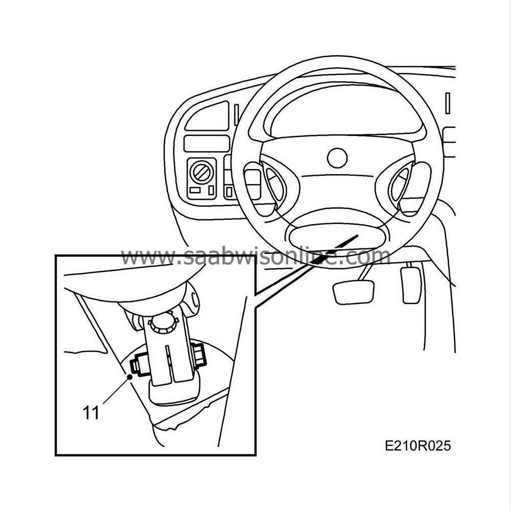
Tightening torque 25 Nm (19 lbf ft). |
|
| 12. |
Fit the left-hand engine mounting but without tightening it. Fit the right-hand engine mounting with yoke but do not tighten.

|
|
| 13. |
Raise the car slightly, remove the wedges and lower the car to the floor.
|
|
| 14. |
Tighten the engine mountings, using a torque wrench.
Tightening torque: 50 Nm (36 lbf ft). |
|
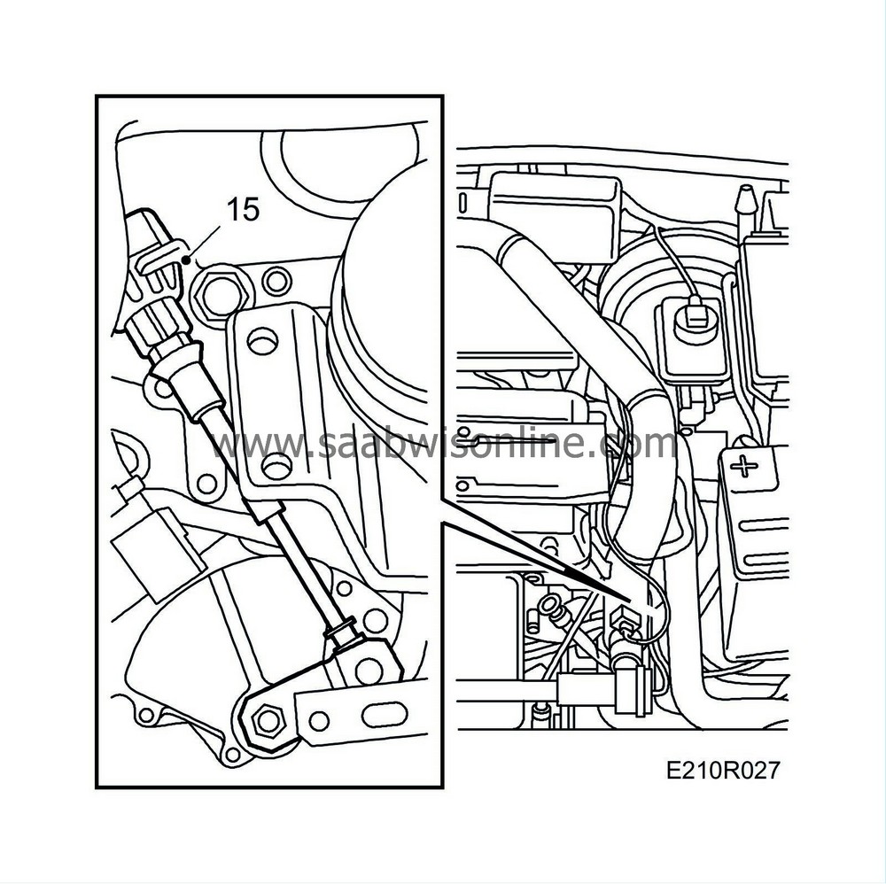
| 15. |
Fit the selector lever cable. (aut)
|
|
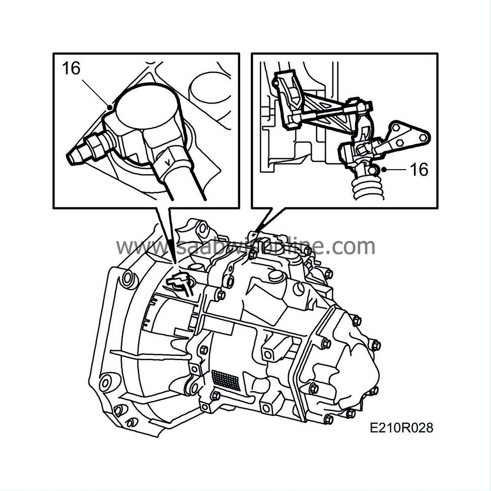
| 16. |
Lock 4th gear with
Locking pin, gear position adjustment
87 92 335 (ring up) in the gearbox and (ring down) in the gear shift housing. Fit the selector rod. Remove the locking pins and fit a new plastic plug in the gearbox. Try changing gear. (man)
|
|
| 17. |
Move the bleeder hose up under the main fuse box. (aut)
|
|
| 18. |
Connect the hoses to the heat exchanger.

|
|
| 19. |
Connect the coolant hose to the expansion tank.
|
|
| 20. |
Secure the engine wiring harness with bracket to the bulkhead.

|
|
| 21. |
Fit the engine control module, the cover panel over the wiper mechanism and the wiper arms.
|
|
| 22. |
Connect the ground cable to the gearbox.

|
|||||||||
| 23. |
Connect the positive cable to the positive terminal.
|
|
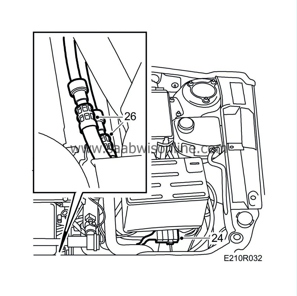
| 24. |
(aut.) Plug the connector with electrical leads into the gearbox. Fit the bracket in place.
|
|
| 25. |
(man.) Plug in the reversing lights connector.
|
|
| 26. |
Connect the quick-release couplings to the automatic transmission fluid cooler.
|
|
| 27. |
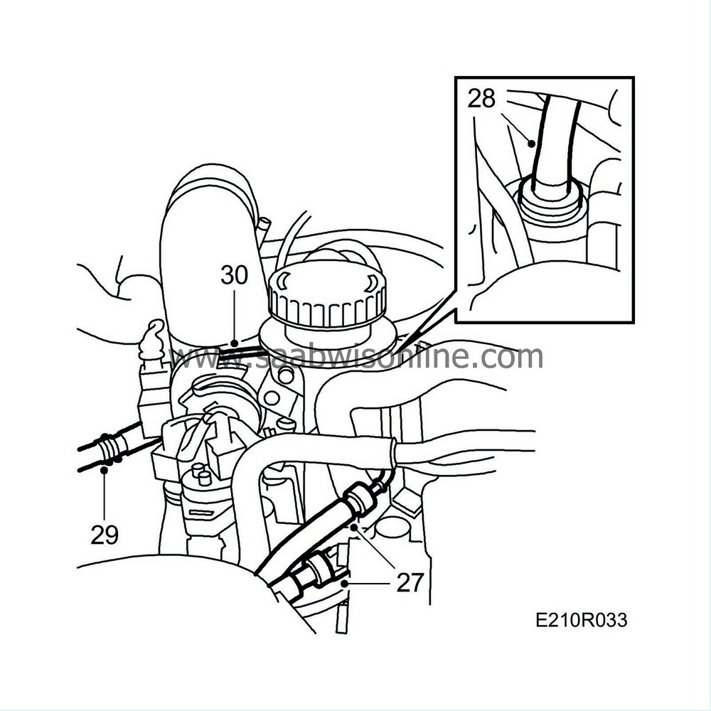
Couple together the two fuel connections and the rubber protectors.
|
|
| 28. |
Connect the vacuum hose from the brake servo to the intake manifold.
|
|
| 29. |
Connect the vacuum hose from the EVAP canister purge valve to the intake manifold.
|
|
| 30. |
Refit the throttle cable.
|
||||||||||
| 31. |
Raise the car slightly.
|
|
| 32. |
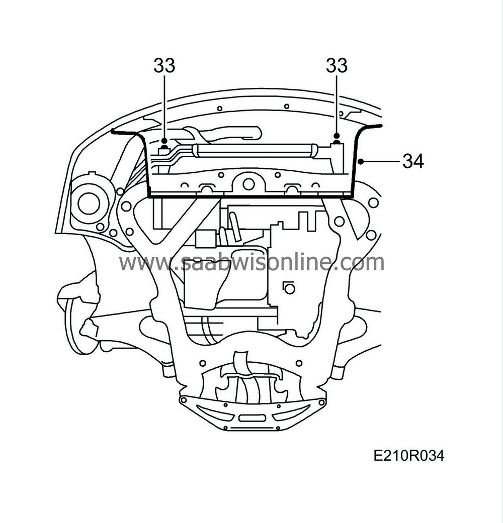
Fit the hose between the turbocharger and charge air cooler.
|
|
| 33. |
Mount the engine oil cooler on the other coolers.
|
|
| 34. |
Fit the cover under the cooler.
|
|
| 35. |
Lower the car to the floor.
|
|
| 36. |
Remove the fastening straps supporting the coolers.
|
|
| 37. |
Check that the A/C compressor pipe is correctly positioned.
|
|
| 38. |
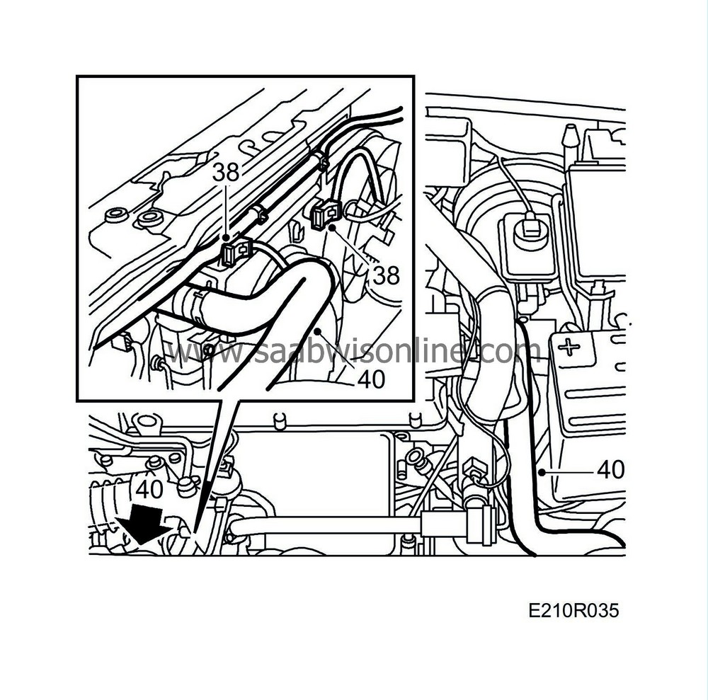
Fit the radiator fans and plug in the electrical connectors.
|
|
| 39. |
Refit the front grille.
|
|
| 40. |
Reconnect the upper and lower radiator hoses.
|
|
| 41. |
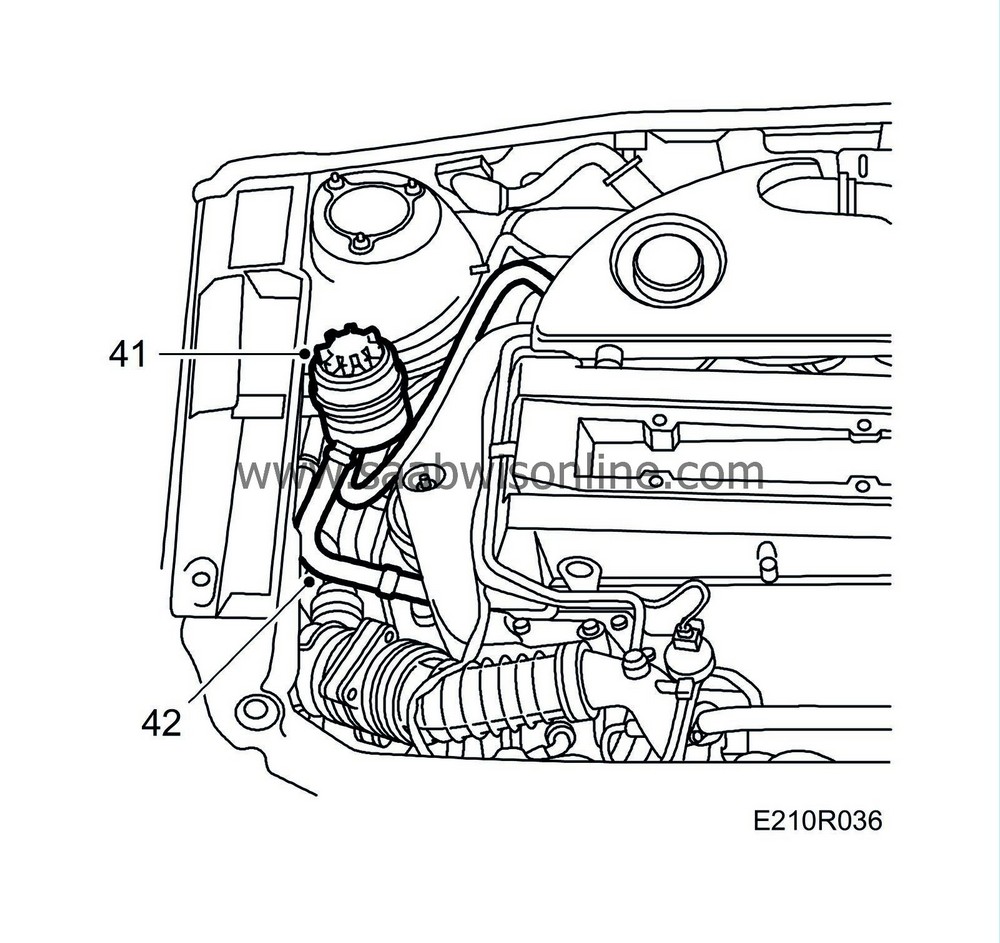
Refit the power steering fluid reservoir.
|
|
| 42. |
Reconnect the pipes to the power steering pump.
|
|
| 43. |
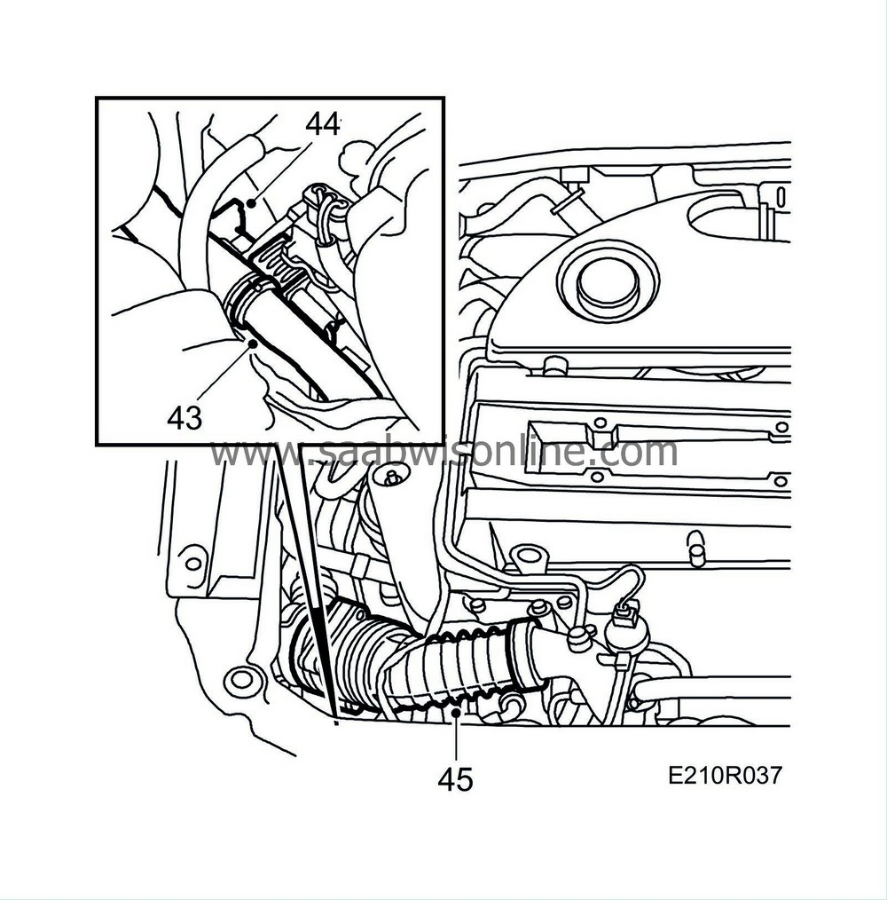
Reconnect the quick-release coupling on the vacuum hose connected to the turbo wastegate.
|
|
| 44. |
Plug in the A/C compressor's connector.
|
|
| 45. |
Refit the mass air flow sensor's rubber gaiter and plug in the connector.
|
|
| 46. |
Fit the bypass valve with intake manifold and its vacuum hose.
|
|
| 47. |
Fit the hose between the pressure pipe and charge air cooler and connect the temperature sensor switch.
|
|
| 48. |
Fit the wheels and tighten the wheel bolts, using a torque wrench.
Tightening torque: 110 Nm (80 lbf ft).
|
||||||||||
| 49. |
Lower the car and tighten the hub centre nuts to torque. Use new hub centre nuts (with face groove)
Tightening torque 170 Nm + 45° (125 lbf ft + 45°). |
|
| 50. |
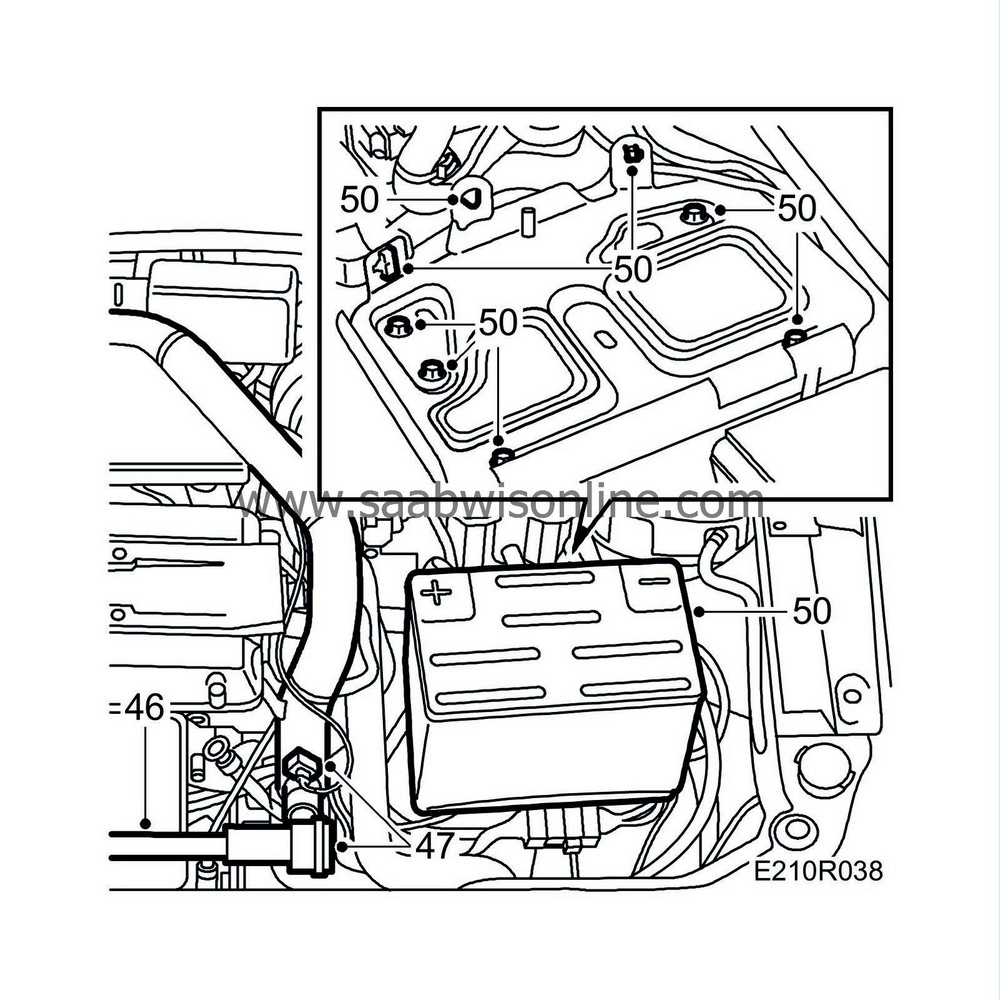
Fit the battery tray, the battery, the cover over the intake manifold and the battery cover. Remove the wing covers. Fit the vacuum hose to the heat exchanger shut-off valve (cars with AC).
|
|
| 51. |
Fill the radiator with coolant and check the system for leaks.
|
|
| 52. |
(aut.) Fill up with transmission fluid via the transmission dipstick tube.
|
|
| 53. |
Top up the engine oil, check other oil and fluid levels and top up as necessary. Make sure that the engine, engine bay and cabin are clean.
|
|
| 54. |
Secure all hoses and cables that have been disconnected.
|
||||||||||||||||||
| 55. |
Bleed the cooling system as follows: If the car is equipped with A/C or ACC, it must be turned off since these will start the radiator fan. Fill the system to the MAX level, close the pressure cap, start the engine and warm it, preferably at varying engine speeds, until the radiator fan starts. Then fill the system to MAX once more.
|
|
| 56. |
Test drive the car and check all functions. Check that the steering wheel stands straight when driving on a straight road. Also check the oil level in the engine and gearbox.
|
|
| 57. |
Set the clock to the correct time. Calibrate the ACC.
|
|


 Warning
