Cruise control
| Cruise control |

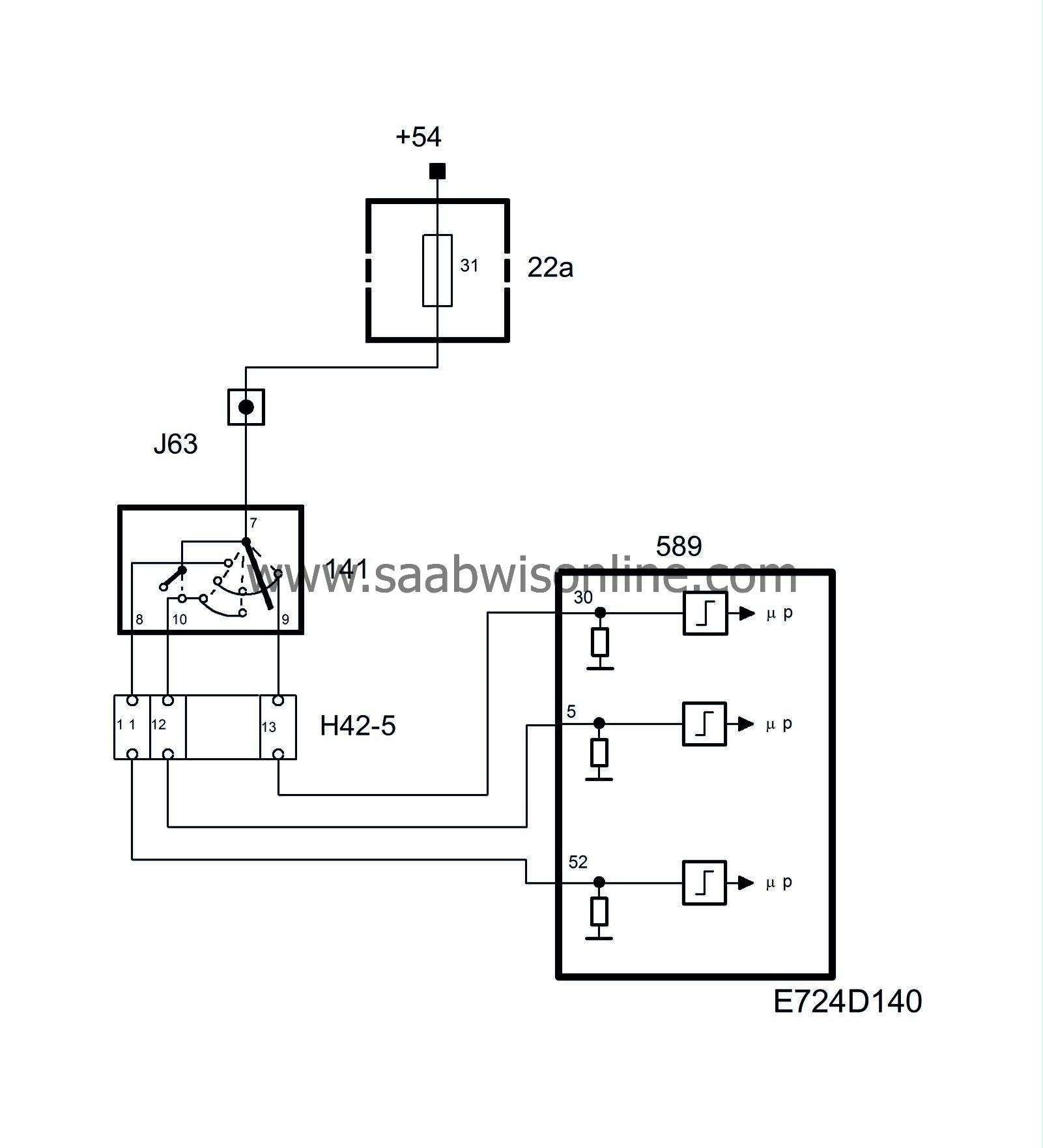
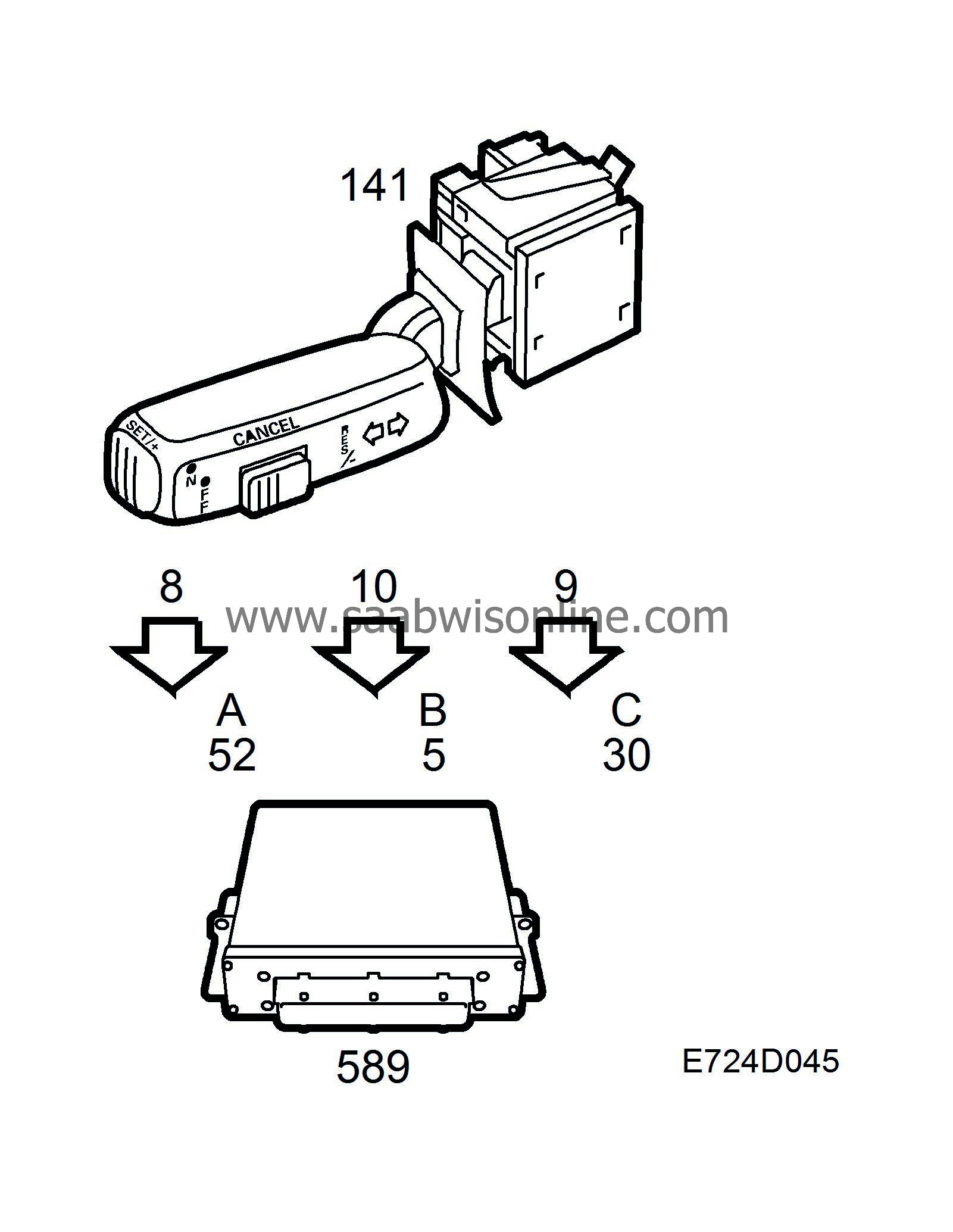
Cruise control is operated with the switch on the direction indicator stalk switch. The switch is powered from +54 and has three outputs to the control module (see adjacent table).
When the switch is put in position "ON", the control module will send bus information "CRUISE lamp ON". The main instrument unit will then turn on the lamp.
When the "SET" button is subsequently pressed, the control module will store the current speed in its memory on condition that other conditions for cruise control have been fulfilled.
The control module then reads through a table containing the rolling resistance on level ground at various speeds. The requested (stored) speed has now been converted to a requested drive wheel torque.
The requested drive wheel torque is then compared with the current gear and is converted to requested engine torque.
Requested engine torque is converted to requested air mass/combustion and constitutes the cruise control input signal to the air mass control.
If the vehicle speed is lower than that requested, the requested air mass/combustion is increased until the acceleration reaches a certain level. In the same way, the requested air mass/combustion is reduced until deceleration reaches a certain level if the speed is higher than that requested.
The control module is programmed for cruise control even if cruise control is not fitted as original equipment. Retrofitting is therefore simple.
|
From switch pin
|
To control module pin
|
Connection designation in diagnostic tool
|
SWITCH POSITION
|
|
|
|
|
|
Zero position
|
ON/OFF
|
SET/+
|
RES/-
|
CANCEL
|
|||
|
8
|
52
|
A
|
0
|
1
|
0
|
0
|
0
|
|
10
|
5
|
B
|
0
|
1
|
1
|
0
|
1
|
|
9
|
30
|
C
|
0
|
1
|
0
|
1
|
1
|
Zero position
The switch is spring-loaded to zero position. None of the switch connections A, B or C are energized.ON/OFF
When the switch is moved to the far left, connections A, B and C are energized. The ON/OFF switch has two functions, alternately ON and OFF.CANCEL
Between zero position and ON/OFF, switch connections B and C are energized. This position has the same function as when the brake pedal or clutch pedal is depressed, i.e. cruise control is disengaged but the set speed is retained in memory.RES/-
When the switch is moved to the right from zero position, connection C is energized. This position has three functions:| 1. |
Engages cruise control and stores the current speed in memory unless a speed is already stored there.
|
|
| 2. |
Engages cruise control if the speed is stored in memory but cruise control was cancelled with CANCEL, the brake or the clutch.
|
|
| 3. |
If the position is selected while cruise control is active, the speed will decrease. When the switch returns to zero position, the current speed is stored and the cruise control function continues.
|
|
If this position is selected for a shorter time than 300 ms, the requested speed is decreased by 1.6 km/h (1 mph).
SET/+
At the end of the direction indicator stalk switch, there is a spring-loaded pushbutton. When the button is pressed, connection B will be energized. This position has two functions:| 1. |
Engage cruise control and store the current speed in memory irrespective of whether any other speed has previously been stored there.
|
|
| 2. |
The speed increases if the button is pressed. Once the button is released, the current speed will be stored and cruise control continues.
|
|
If the button is pressed for a shorter time than 300 ms, the requested speed is increased by 1.6 km/h (1 mph).
The following conditions must be fulfilled before cruise control can be engaged:
| 1. |
Brake light switch = 0
|
|
| 2. |
Clutch and brake pedal switches = 0
|
|
| 3. |
Speed, wire from ABS >40 km/h.
|
|
| 4. |
Speed, bus from MIU >40 km/h.
|
|
| 5. |
Rapid deceleration = 0.
|
|
| 6. |
No TCS Active (Wire from TC/ABS).
|
|
| 7. |
Manual gearbox: Gear ratio corresponds with one of the gears. Automatic transmission: D, 3, 2 or 1.
|
|
| 8. |
Brake light switch and clutch/brake pedal switches simultaneously = 1 at some time during this driving cycle.
|
|
| 9. |
No diagnostic trouble code blocking throttle control.
|
|
| 10. |
Inputs A, B and C = 0 prior to switch being moved to ON/OFF.
|
|
| 11. |
Cruise control engaged with switch.
|
|
| Pedal switches, brake and clutch |


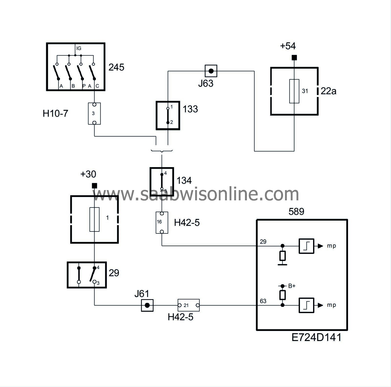
When the brake or clutch pedal is depressed, the pedal switches will cut the power supply to control module pins 29 and cruise control will be disengaged. On cars with automatic transmission, the circuit is powered from the gear selector position sensor in positions D, 3, 2 and 1. The pedal switches are works-fitted on all cars with manual gearbox, even those without cruise control.
| Brake light switch |
When the brake pedal is depressed, the normally open pair of contacts in the brake light switch will close and B+ will be applied on control module pin 63.
Brake light information is used by the control module to:
| • |
disengage cruise control
|
|
| • |
enable engine torque limitation
|
|
| • |
enable diagnosis of the speed signal.
|
|
| Diagnostics |
| • |
The diagnostic tool contains a menu that indicates the condition that has not been fulfilled if cruise control cannot be engaged. Another menu indicates the reason why cruise control was disengaged when it was last used.
|
|
| • |
If the input from the brake light switch is continuously B+, diagnostic trouble code P1576 will be generated. If the input from the brake light switch is continuously 0V, diagnostic trouble code P1577 will be generated.
|
|
System reaction to a fault
| • |
Cruise control will be blocked if a fault occurs on the input from the brake light switch.
|
|


