Test readings, control module connections
|
|
Test readings, control module connections
|
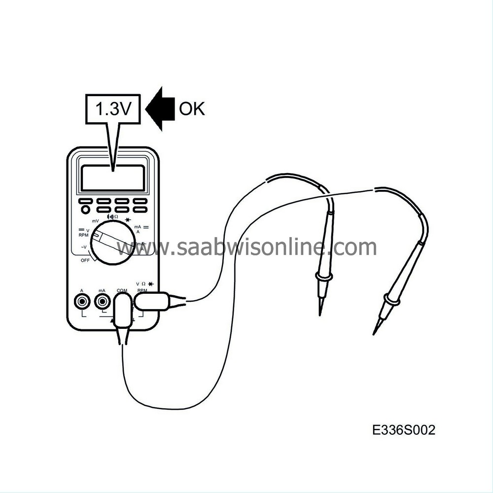
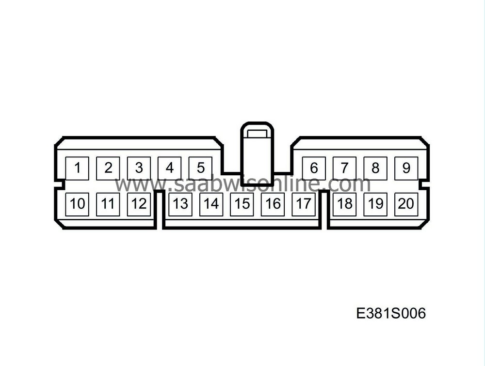
 The following pages include values and directions for measuring signals and levels on the main instrument unit and its control module.
|
•
|
Note the test conditions, use common sense when assessing the test results.
|
|
•
|
First check that the control module is supplied with current and is grounded.
|
|
•
|
Then check all the sensor inputs and signals from other systems.
|
|
•
|
Lastly, check the control module outputs. Remember, the test values do not say anything about whether or not the actuator is in working order.
|
|
•
|
If any reading is not OK, consult the wiring diagram to trace the leads, connectors or components which ought to be checked more thoroughly.
|
|
•
|
The test readings indicated are in respect of calibrated FLUKE 88/97.
|
|
•
|
The test values %(+) and ms(+) indicate the pulse ratio and pulse duration of the signal. A test instrument for measuring pulse ratio and pulse duration must be used. The (+) sign indicates a positive trigger pulse, TRIG+.
|

Pin
|
Pin BOB
|
Cable colour
|
Component/Function
|
In/Out
|
Test conditions
|
Test between
|
Test reading
|
See
|
1 (K12)
|
21
|
BU/RD
|
Battery voltage (+15 circuit)
|
In
|
Ignition ON
|
21-B+
|
< 0.5 V
|

|
2 (K12)
|
22
|
BK
|
Ground
|
In
|
Ignition ON
|
22-B-
|
< 0.5 V
|

|
3 (K12)
|
23
|
BK
|
Ground
|
In
|
Ignition ON
|
23-B-
|
< 0.1 V
|

|
4 (K12)
|
24
|
GN
|
P bus (+)
|
In/Out
|
Ignition ON
|
24-22
|
2.5 V
|

|
5 (K12)
|
25
|
GN
|
I bus (+)
|
In/Out
|
Ignition ON
|
25-22
|
2.5 V
|

|
6 (K12)
|
26
|
BU/RD
|
Battery voltage (+15 circuit)
|
In
|
Ignition ON
|
26-B+
|
< 0.5 V
|

|
7 (K12)
|
27
|
RD
|
Battery voltage (+30 circuit)
|
In
|
Ignition ON
|
27-B+
|
< 0.5 V
|

|
8 (K12)
|
28
|
GY/WH
|
Ground, Sensor ground, fuel level sensor
|
Out
|
Ignition ON
|
28-B-
|
< 0.1 V
|

|
9 (K12)
|
29
|
YE/WH
|
Sensor, fuel level
|
In
|
Ignition ON
|
29-28
|
0.5-3.7 V
|

|
10 (K12)
|
30
|
VT
|
Wheel speed, Rear left
|
In
|
Rotate wheel slowly
|
30-32
|
0 V B+
(LP
HI
LOp)
|

|
Rotate wheel 1/2 revolution per second
|
30-22
|
15 Hz 50%
(LP
HI
LOp)
|
|
11 (K12)
|
31
|
WH
|
P bus (-)
|
|
Ignition ON
|
31-22
|
2.5 V
|

|
12 (K12)
|
32
|
WH
|
I bus (-)
|
|
Ignition ON
|
32-22
|
2.5 V
|

|
> = greater than; < = less than; ~ = alternating current (LP: LOGIC PROBE P = select pulse; p = visible pulse)

Pin
|
Pin BOB
|
Cable colour
|
Component/Function
|
In/Out
|
Test conditions
|
|
Test between
|
Test reading
|
See
|
1 (K20)
|
1
|
VT/WH
|
Warning lamp, AIRBAG
|
In
|
Ignition ON
|
On
|
1-B-
|
0 V
|

|
Out
|
1-B-
|
B+
|
|
2 (K20)
|
2
|
YE
|
Engine oil pressure warning lamp
|
In
|
Ignition ON
|
On
|
2-B-
|
0 V
|

|
Out
|
2-B-
|
B+
|
|
3 (K20)
|
3
|
GN/WH
|
Warning lamp, charging
|
In
|
Ignition ON
|
On
|
3-B-
|
0 V
|

|
Out
|
3-B-
|
B+
|
|
4 (K20)
|
4
|
|
No connection
|
|
|
|
|
|
|
5 (K20)
|
5
|
|
No connection
|
|
|
|
|
|
|
6 (K20)
|
6
|
|
No connection
|
|
|
|
|
|
|
7 (K20)
|
7
|
|
No connection
|
|
|
|
|
|
|
8 (K20)
|
8
|
|
No connection
|
|
|
|
|
|
|
9 (K20)
|
9
|
YE/RD
|
Lights-on indicator lamp
|
In
|
Ignition ON
|
On
|
9-B-
|
B+
|

|
Out
|
9-B-
|
0 V
|
|
10 (K20)
|
10
|
OG
|
ABS warning lamp
|
In
|
Ignition ON
|
On
|
10-B-
|
0 V
|

|
Out
|
10-B-
|
B+
|
|
11 (K20)
|
11
|
GN
|
Warning lamp, handbrake
|
In
|
Ignition ON
|
On
|
11-B-
|
0 V
|

|
Out
|
11-B-
|
B+
|
|
12 (K20)
|
12
|
BU
|
Warning lamp, brake fluid level
|
In
|
Ignition ON
|
On
|
12-B-
|
0 V
|

|
Out
|
12-B-
|
B+
|
|
13 (K20)
|
13
|
GY/BK
|
TCS indicator lamp
|
In
|
Ignition ON
|
On
|
13-B+
|
B+
|
|
|
|
|
|
|
|
|
Out
|
13-B+
|
< 0.5 V
|
|
14 (K20)
|
14
|
|
No connection
|
|
|
|
|
|
|
15 (K20)
|
15
|
WH
|
Main beam indicator lamp
|
In
|
Ignition ON
|
On
|
15-B-
|
B+
|

|
Out
|
15-B-
|
0 V
|
|
16 (K20)
|
16
|
|
No connection
|
|
|
|
|
|
|
17 (K20)
|
17
|
|
No connection
|
|
|
|
|
|
|
18 (K20)
|
18
|
|
No connection
|
|
|
|
|
|
|
19 (K20)
|
19
|
|
No connection
|
|
|
|
|
|
|
20 (K20)
|
20
|
GY/GN
|
Indicator lamp, TCS OFF
|
In
|
Ignition ON
|
On
|
20-B+
|
B+
|
|
|
|
|
|
|
|
|
Out
|
20-B+
|
< 0.5 V
|
|
> = greater than; < = less than; ~ = alternating current (LP: LOGIC PROBE P = select pulse; p = visible pulse)


