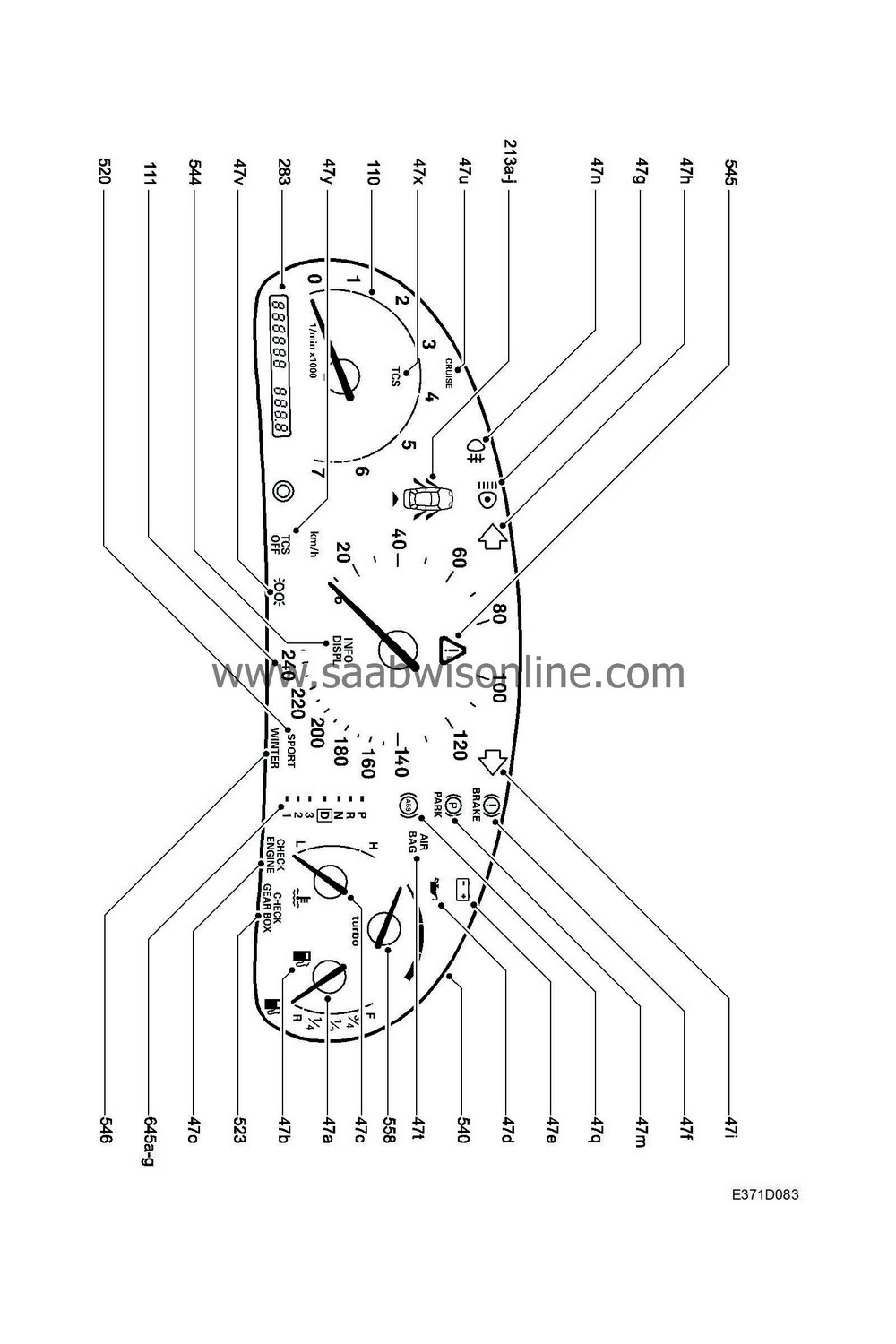
|
No.
|
Name
Location
|
Illus.
|
|
Components
|
|
2
|
Generator
on rear long side of engine (right)
|

|
10
|
Switch, lamp
on dashboard between steering wheel and driver's door
|

|
11FL
|
Lamp, main beam, left
in LH headlamp
|

|
13FL
|
Lamp, LH front parking light
in LH headlamp
|

|
22a
|
Fuse box, dashboard
on end of dashboard next to driver's door
|

|
42
|
Level switch, brake fluid
on brake fluid reservoir
|

|
43
|
Handbrake switch
under floor console by handbrake
|

|
44
|
Pressure switch, engine oil
4-cyl:
under intake manifold
V6:
on RH end of engine below generator
|

|
46
|
Level sensor, fuel
in fuel tank
|

|
331
|
SRS/Airbag control module
on centre tunnel behind handbrake
|

|
342a
|
Fuse box, engine bay
behind the battery
|

|
382
|
Control module, TC-ABS
integrated in brake unit behind battery
|

|
540
|
Main instrument unit
in front of driver in dashboard
|

|
547
|
Control module, ABS
integrated in brake unit behind battery
|

|
|
4-pin connector
|
|
H4-1
|
At generator
|

|
H4-2
|
Under rear seat
|

|
|
42-pin connector
|
|
H42-5
|
In the centre of the bulkhead partition (engine bay side)
|

|
|
43-pin connector
|
|
H43-1
|
White connector in connector bracket under LH A-pillar
|

|
|
80-pin connector
|
|
H80-1
|
In the connector bracket under the LH A-pillar.
|

|
|
Crimp connectors
|
|
J42
|
LHD:
Approx. 100 mm from branching of grounding point G40 towards relay box
RHD:
Approx. 50 mm from branching of grounding point G42 towards relay box
|

|
J58
|
LHD:
Approx. 50 mm from the MIU branching (12-pin connector) towards the data link connector
RHD:
Approx. 100 mm from the SID branching towards the radio.
|

|
J60
|
LHD:
Approx. 30 mm from branching of DICE control module towards main fuse box
RHD:
Approx. 20 mm from branching of DICE control module towards engine bay grommet
|

|
|
Grounding points
|
|
G30
|
In engine bay on side panel in front of LH wheel housing
|

|
G40
|
In cabin on LH side of knee member
|

|
G41S
|
LH ground screw on centre of knee member (in cabin)
|

|
G42
|
In cabin on RH side of knee member
|

|

