(391-1872) Incorrect wiring harness for microphone in telephone installation pre-wiring
|
TECHNICAL SERVICE BULLETIN
|
|
Bulletin Nbr:
|
391-1872
|
|
Date:
...........
|
FEBRUARI 1998
|
|
Market:
|
Ej US, CA
|
|
|
Incorrect wiring harness for microphone in telephone installation pre-wiring
|
Saab 9-5 up to and including W3059826 (M98)
An unscreened wiring harness for the microphone has been mistakenly fitted in the telephone installation pre-wiring on cars up to and including the above VIN. This has lead to superfluous noise being emitted from the microphone.
41 09 187 3-pin connector, microphone
40 63 970 Cable lugs, (2 pcs)
91 20 957 Cable lugs, (2 pcs)
Microphone cable, approx. 2.5 m
|
-
|
Twin screened cable with PVC insulation, 2 x 0.5 mm. Screen conductor, 0.5 mm.
|
|
Note
|
|
Check with the telephone manufacturer whether the phone uses high or low level for the microphone input before starting work.
|
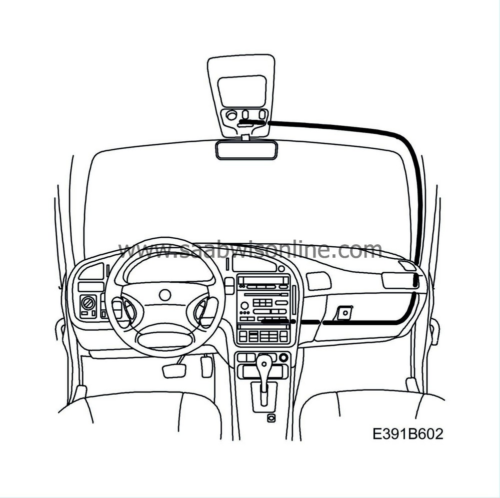
The above illustration shows how the new screened cable is to be laid in the car up to the microphone in the roof console.
|
1.
|
Remove the SID unit, radio and radio compartment, and the ACC/MCC unit.
|
|
2.
|
Remove the glove box, cover under the glove box, trim cover on the centre console and the A-pillar trim on the passenger side.
|
|
3.
|
Remove the sun visor and front courtesy handle on the passenger side and the roof console.
|
Work to carry out on the roof console
|
1.
|
Insert the screened cable through the headlining, from the windscreen up to the roof console. Unplug the microphone connector and cut the wiring harness at the nearest cable holder in the roof.

|
|
2.
|
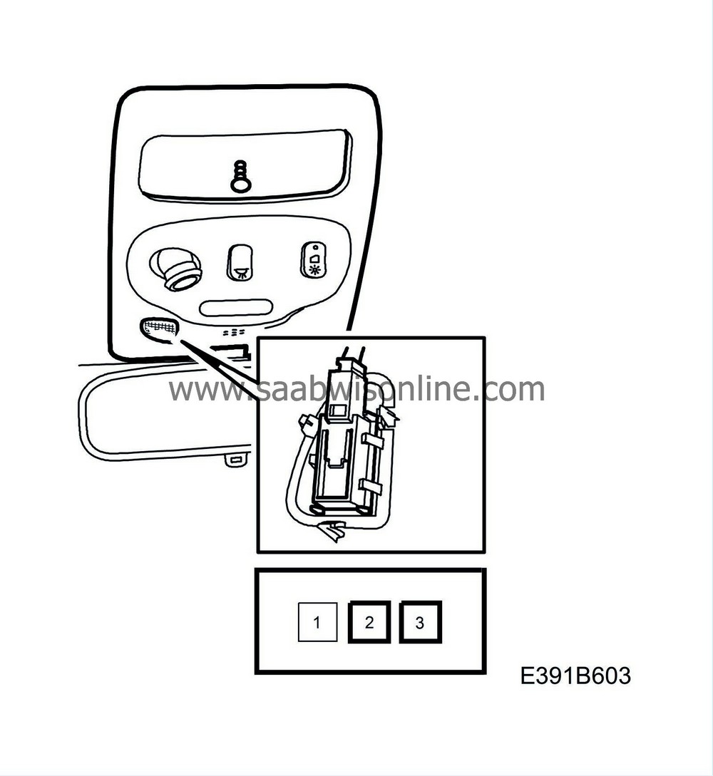
Fit 2 cable lugs on the new wiring harness as specified in the table and connect the new wiring harness to the microphone connector in the roof console.
Connect the wiring harness to the microphone.
|
Pin
|
Function
|
1
|
High level, microphone input
|
2
|
Low level, microphone input
|
3
|
Microphone ground
|
|
|
3.
|
Run the wiring harness down to the dashboard via the A-pillar on the passenger side.
|
|
4.
|
Secure the wiring harness to the roof and along the A-pillar on the passenger side. Use pieces of adhesive tape to prevent squeaking and rattling.
|
Work to be carried out on the centre console
|
1.
|
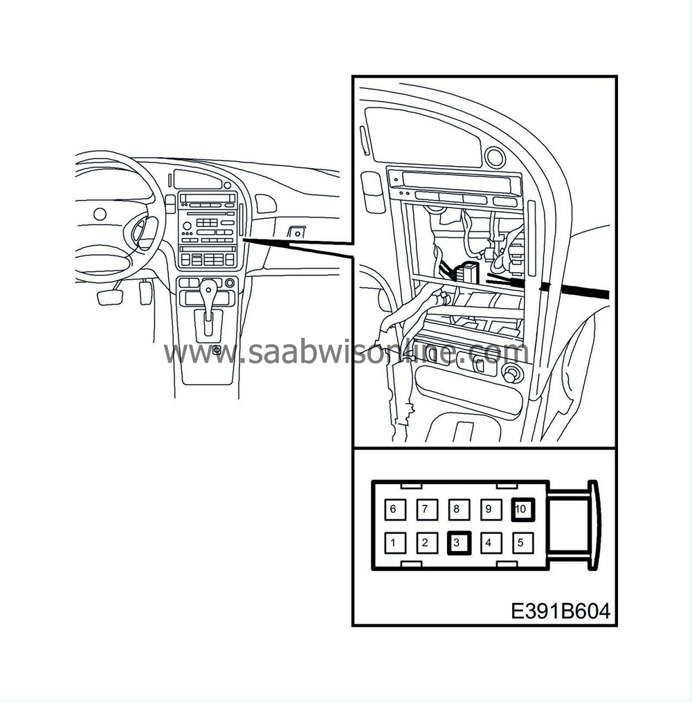
Fasten the wiring harness along the existing harness towards the centre console. Detach the 10-pin connector from its holder on the heating and ventilation unit.

|
|
2.
|
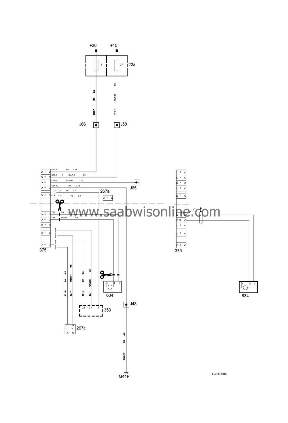
Extract the pins on the brown/grey cable in pos. 10 and the green cable in pos. 3, see the wiring diagram on the last page. Cut off the cable on the extracted pins at the beginning of the wiring harness.
|
|
3.
|
Fit 2 cable lugs to the cables from the new wiring harness as shown in the table. The cable from microphone connector pin 3 and the wiring harness screen both connect to pin 3 in the 10-pin connector in the centre console. To insulate the screen, fit a piece of shrink sleeve at the end of the wiring harness.
|
Function
|
Pin 10-pin connector
|
Pin 3-pin connector
|
Power supply (+30 circuit)
|
1
|
-
|
Power supply (+15 circuit)
|
2
|
-
|
Ground, microphone
|
3 (+screen)
|
3
|
Ground, mobile phone
|
4
|
-
|
Telephone mute
|
5
|
-
|
Rheostat
|
6
|
-
|
Telephone output signal
|
7
|
-
|
Telephone output ground
|
8
|
-
|
Not used
|
9
|
-
|
Microphone output
|
10
|
2 (low level) 1 (high level)
|
|
|
4.
|
Fasten the new wiring harness for the microphone to the harness on the heating and ventilation unit with a cable tie.
|
|
5.
|
Refit the 10-pin connector in its holder on the heating and ventilation unit and fasten the new wiring harness along the harness towards the A-pillar.
|
|
6.
|
Check the function of the microphone.
|
|
7.
|
Refit all dismantled components.
|
|
Warranty/Time information
|
Failed Object: 37 130
Fault/Reason code: 40
Location code: 09
Warranty Type (US):
Repair/Action code: 01
Labour Operation (US):
Time: 0.9 hours


