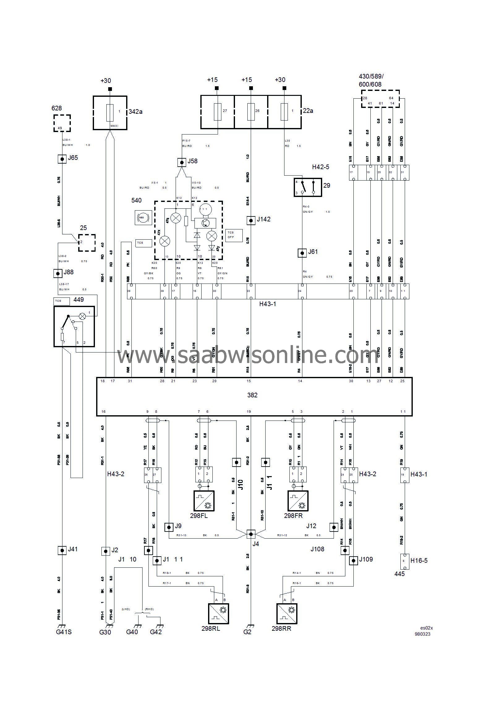
Anti-lock brakes with Traction Control TC/ABS 5.3
| Anti-lock brakes with Traction Control TC/ABS 5.3 |
| List of components |
| No. | Name Location | Fig. |
|
Components
|
||
|
22a
|
Main fuse board, dashboard,
on end of dashboard by driver's door |

|
|
25
|
Switch, hazard flashers,
by centre dashboard vent |

|
|
29
|
Brake-light switch,
on pedal bracket |

|
|
298FL
|
Wheel speed sensor, front left,
on left-hand steering swivel member |

|
|
298FR
|
Wheel speed sensor, front right,
on right-hand steering swivel member |

|
|
298RL
|
Wheel speed sensor, rear left,
on left-hand rear hub |

|
|
298RR
|
Wheel speed sensor, rear right,
on right-hand rear hub |

|
|
342a
|
Main fuse board, engine bay,
behind battery |
mLINK
|
|
382
|
Control module, TC/ABS,
integrated in hydraulic unit behind battery |

|
|
430
|
Control module, Trionic 4-cyl,
in space (cabin side) ahead of windscreen on passenger side |

|
|
445
|
Data link connector, 16-pin, CARB,
under dashboard by steering column |

|
|
449
|
Switch, TCS,
in dashboard between steering wheel and centre dashboard vent |

|
|
540
|
Main instrument unit,
ahead of driver in dashboard. |

|
|
600
|
Control module, Trionic V6,
in space (cabin side) ahead of windscreen on passenger side |

|
|
608
|
Control module, Trionic V6 OBDII,
in space (cabin side) ahead of windscreen on passenger side |

|
|
628
|
DICE control module
LHD: above main relay board in dashboard RHD: behind main relay board in dashboard |

|
|
|
16-pin connectors |
|
|
H16-5
|
Under dashboard by steering column
|

|
|
|
42-pin connectors |
|
|
H42-5
|
Middle of bulkhead (engine bay side).
|

|
|
|
43-pin connectors |
|
|
H43-1
|
White connector on connector bracket below left-hand A-pillar
|

|
|
H43-2
|
Blue connector on connector bracket below left-hand A-pillar
|

|
|
|
Crimp connections |
|
|
J2
|
Approx. 20 mm from branching point grounding point G30 towards the TC/ABS control module.
|

|
|
J4
|
Approx. 75 mm from branching point grounding point G30 towards the TC/ABS control module.
|

|
|
J9
|
In connector housing to TC-ABS control module
|

|
|
J10
|
In connector housing to TC-ABS control module
|

|
|
J11
|
In connector housing to TC-ABS control module
|

|
|
J12
|
In connector housing to TC-ABS control module
|

|
|
J41
|
LHD:
Approx. 200 mm from branching point SID towards MIU
RHD: Approx. 90 mm from branching point G41S grounding point towards the MIU |

|
|
J58
|
LHD:
Approx. 50 mm from branching point MIU (12-pin connector) towards the diagnostics connector.
RHD: Approx. 100 mm from branching point SID towards the radio. |

|
|
J61
|
LHD:
Approx. 90 mm from branching point left-hand front floor lamp towards the DICE control module.
RHD : Approx. 210 mm from branching point G40 grounding point towards the radio. |

|
|
J65
|
LHD:
Approx. 40 mm from branching point MIU (20-pin connector) towards its 12-pin connector.
RHD: Approx. 260 mm from branching point G41S grounding point towards the MIU. |

|
|
J88
|
LHD:
Approx. 10 mm from branching point G41S grounding point towards the SID.
RHD: Approx. 160 mm from branching point G41S grounding point towards the MIU. |

|
|
J108
|
Approx. 270 mm from branching point fuel pump/EVAP pressure sensor towards rear left door
|

|
|
J109
|
Approx. 295 mm from branching point fuel pump/EVAP pressure sensor towards rear left door
|

|
|
J110
|
Approx. 345 mm from branching point fuel pump/EVAP pressure sensor towards rear left door
|

|
|
J111
|
Approx. 370 mm from branching point fuel pump/EVAP pressure sensor towards rear left door
|

|
|
J142
|
LHD:
Approx. 60 mm from branching point DICE control module towards engine bay grommet
RHD: Approx. 120 mm from branching point DICE control module towards main fuse board |

|
|
|
Grounding points |
|
|
G2
|
On left-hand structural member behind headlamp (battery ground)
|

|
|
G30
|
In the engine bay on the side panel in front of the left-hand wheel housing
|

|
|
G40
|
In the cabin on the left-hand side of the knee protection bar
|

|
|
G41S
|
Left-hand grounding screw in centre of knee protection bar (in cabin)
|

|
|
G42
|
In the cabin on the right-hand side of the knee protection bar.
|

|


