
Test readings, control-module connections
| Test readings, control-module connections |
| Scope |
The values and readings for measuring signals and levels in the ABS control module are given on the following pages.
| Points to remember: |
| • |
Observe the test conditions. Use common sense in assessing the readings.
|
|
| • |
Start by checking that the control module is receiving power and is grounded.
|
|
| • |
Check all sensor inputs and signals from other systems.
|
|
| • |
Finally, check the control module outputs. Remember that the readings do not provide an indication that the actuator is operating.
|
|
| • |
If any reading is not OK, consult the wiring diagram to trace the leads, connectors or components that need further checking.
|
|
| • |
The specified readings are valid for a correctly calibrated Fluke 88/97.
|
|
| • |
The readings %(+) and ms(+) indicate the pulse ratio and pulse length. A test instrument capable of measuring both pulse ratio and pulse length must be used. The '+' sign denotes a positive trigger pulse (TRIG+).
|
|
| Test readings |
| Important | ||
|
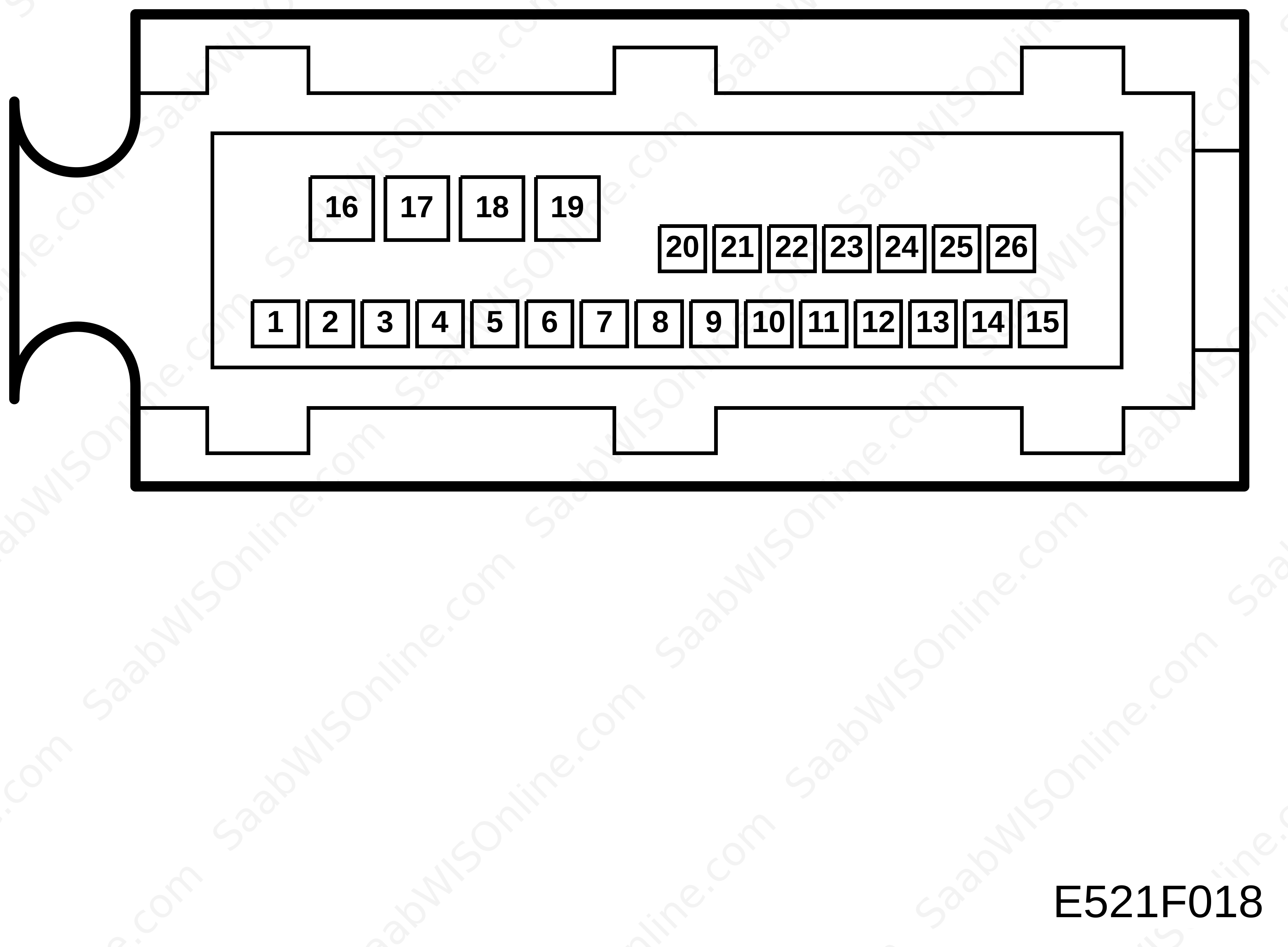
The readings apply to measurements taken on the control module's connector (unplugged) unless otherwise stated. |
||
> = greater than; < = less than; ~ = alternating current (LP: LOGIC PROBE P = select pulse; p = visible pulse)
| Pin | Cable colour | Component/function | In/Out | Test conditions | Measure across | Test reading | See |
|
1
|
WH
|
Wheel sensor, RR: reference ground
|
In
|
Rotate the wheel one turn per second
|
1-2
|
>100 mVAC
|

|
|
2
|
VT
|
Wheel sensor, RR: signal input
|
In
|
Rotate the wheel one turn per second
|
2-1
|
>100 mVAC
|
|
|
3
|
GN
|
Wheel sensor, FR: reference ground
|
In
|
Rotate the wheel one turn per second
|
3-5
|
>100 mVAC
|
|
|
4
|
|
Spare
|
|
|
|
|
|
|
5
|
GY
|
Wheel sensor, FR: signal input
|
In
|
Rotate the wheel one turn per second
|
5-3
|
>100 mVAC
|
|
|
6
|
BU
|
Wheel sensor, FL: reference ground
|
In
|
Rotate the wheel one turn per second
|
6-7
|
>100 mVAC
|
|
|
7
|
VT
|
Wheel sensor, FL: signal input
|
In
|
Rotate the wheel one turn per second
|
7-6
|
>100 mVAC
|
|
|
8
|
BK
|
Wheel sensor, RL: reference ground
|
In
|
Rotate the wheel one turn per second
|
8-9
|
>100 mVAC
|
|
|
9
|
YE
|
Wheel sensor, RL: signal input
|
In
|
Rotate the wheel one turn per second
|
9-8
|
>100 mVAC
|
|
|
10
|
|
Spare
|
|
|
|
|
|
|
11
|
GN
|
Data link
|
In/Out
|
|
|
|
|
|
12
|
|
Spare
|
|
|
|
|
|
|
13
|
|
Spare
|
|
|
|
|
|
|
14
|
GN/GY
|
Brake-light switch
|
In
|
Brake pedal depressed
|
14-16
|
B+
|
|
|
Brake pedal released
|
14-16
|
0 V
|
|
||||
|
15
|
RD/BU
|
Current (+15 circuit)
|
In
|
Ignition ON
|
15-B+
|
<0.5 V
|
|
|
16
|
BK
|
Pump-motor ground
|
In
|
|
16-B-
|
<0.5 V
|
|
|
17
|
RD
|
Current (+30 circuit)
|
In
|
|
17-B+
|
<0.5 V
|
|
|
18
|
RD
|
Current (+30 circuit)
|
In
|
|
18-B+
|
<0.5 V
|
|
|
19
|
BK
|
Ground
|
In
|
|
19-B-
|
<0.5 V
|
|
|
20
|
|
Spare
|
|
|
|
|
|
|
21
|
OG
|
ABS warning lamp
|
In
|
Ignition ON
|
21-B+
|
<0.5 V
|
|
|
22
|
|
Spare
|
|
|
|
|
|
|
23
|
VT
|
Wheel speed, RL
|
Out
|
Rotate wheel slowly
|
|
0/approx. 12 V
Measure on MIU. |
|
|
Rotate the wheel one turn per second
|
|
about 6 V
|
|
||||
|
24
|
|
Spare
|
|
|
|
|
|
|
25
|
GY/RD
|
Wheel speed, FR
|
Out
|
Rotate wheel slowly
|
|
0/approx. 12 V
Measured with Trionic |
|
|
Rotate the wheel one turn per second
|
|
About 6 V
|
|
||||
|
26
|
|
Spare
|
|
|
|
|
|
This project is supported by memberships and donations. If you use this site, please consider Joining SCNA and/or making a donation.
Our Friends