Control module
| Control module |
 ). When the control module is active, the display lights up and diagnostic communication is possible. When the module has been activated by +15, it can assume the following modes:
Engine stationary
If the engine is stationary, there is no coolant circulating through the heat exchanger, the A/C compressor is stationary and the generator is not charging. This means that the system cannot regulate the climate, that the system should not consume current unnecessarily and that there is a risk that a stepping motor may miss a step due to low battery voltage if the starter motor should be engaged. For these reasons, the control module selects rear window heating off, fan current 5 A, air recirculation off and all stepping motors off.Engine running
As soon as the engine has started, the control module regulates all the functions automatically as long as no manual functions have been selected or user programming performed.Ignition OFF
When the ignition is turned off, the display goes out: no buttons work, all the stepping motors are turned off and air recirculation off is selected after 10 seconds. Diagnostics communication remains active if it was active when the ignition was turned off, but it cannot be restarted.The control module processor is active for a further 10 minutes. If the ignition is turned on within these 10 minutes, the control module will retain any manual selections made when the car was last driven. After 10 minutes, the control module starts in AUTO or user programming mode.
If the power supply drops below 9.5 V and the starter motor is not turning, the display will show OFF until the voltage exceeds 10 V.
| Programming |
After changing the ACC unit, a number of parameters must be programmed, see
 .
.
| Diagnostics |
In the event of an internal control module malfunction, diagnostic trouble code B1605 is generated and 01 is displayed instead of right-hand temperature when calibrating.
| Control module power supply |


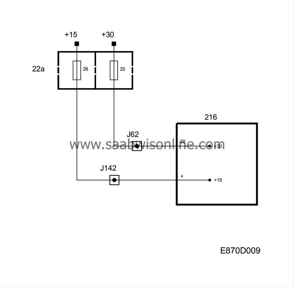
+30
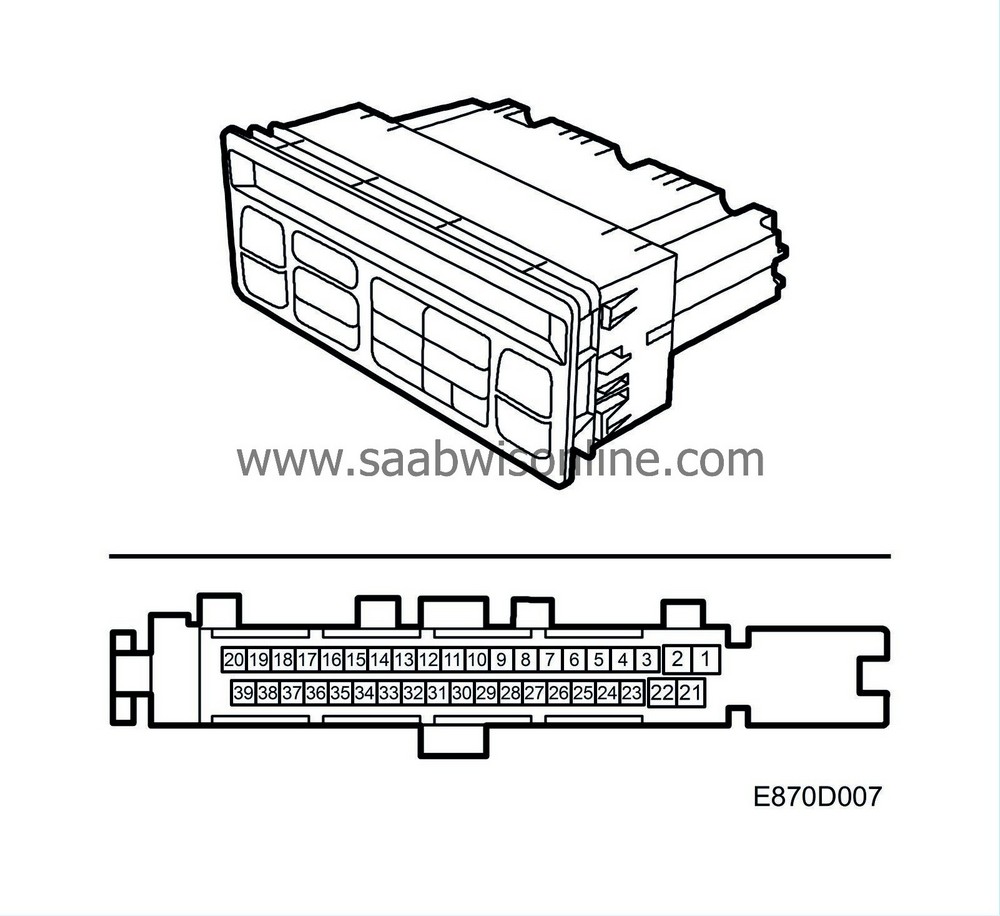
The ACC unit is supplied with current from the +30 circuit on pin 22 via fuse 20.+15
The ACC unit is supplied with current from the +15 circuit on pin 4 via fuse 26. +15 power supply is used to activate the control module.Diagnostics
If the power supply is not present, the display will not light up when the ignition is turned on.| Ground |


Power ground
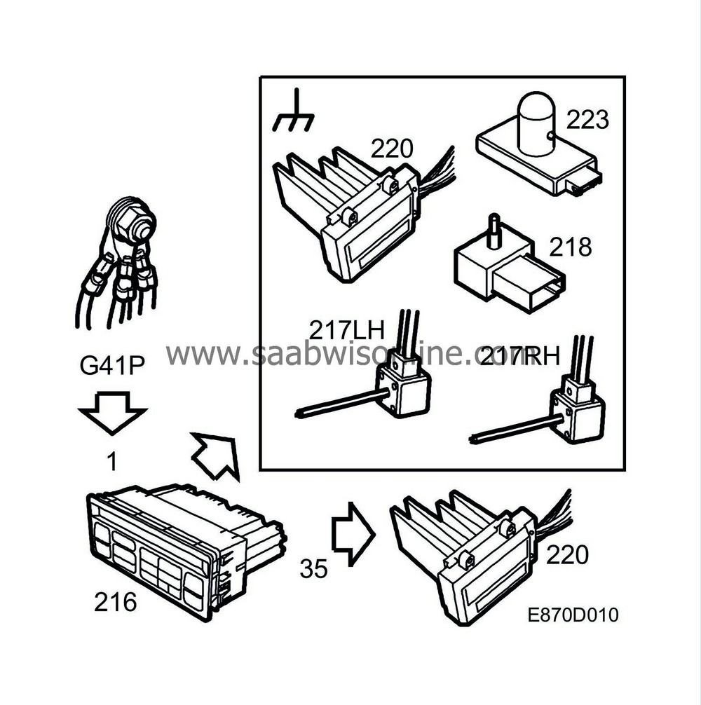
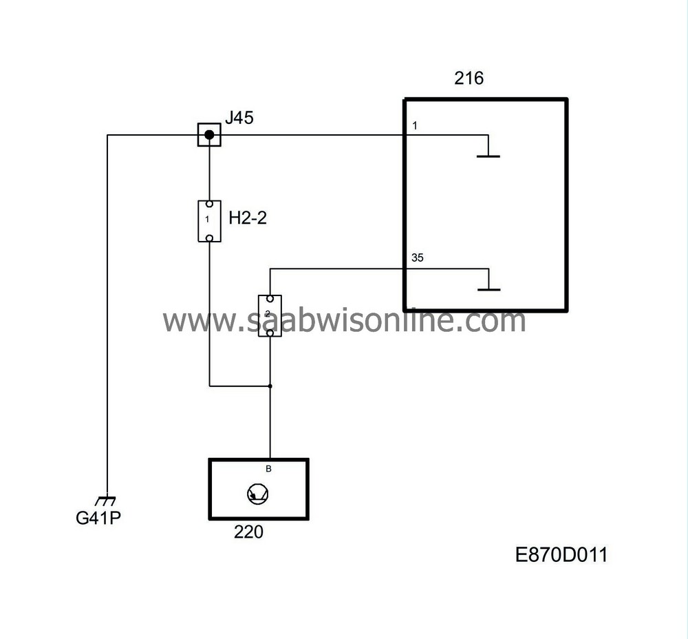
The ACC unit is power grounded on pin 1 from G41P.Sensor ground
All sensors are grounded from separate control module outputs that internally have a common ground via a resistor.Reference ground
The fan control unit's reference ground is obtained from pin 35.Diagnostics
If ground is not present, the display will not light up when the ignition is turned on.If the sensor ground is shorted to 5 V or B+, diagnostic trouble code B2945 is generated and 23 is displayed instead of right-hand temperature when calibrating.


