Test readings, control module connections
| Test readings, control module connections |
| Remember: |
| • |
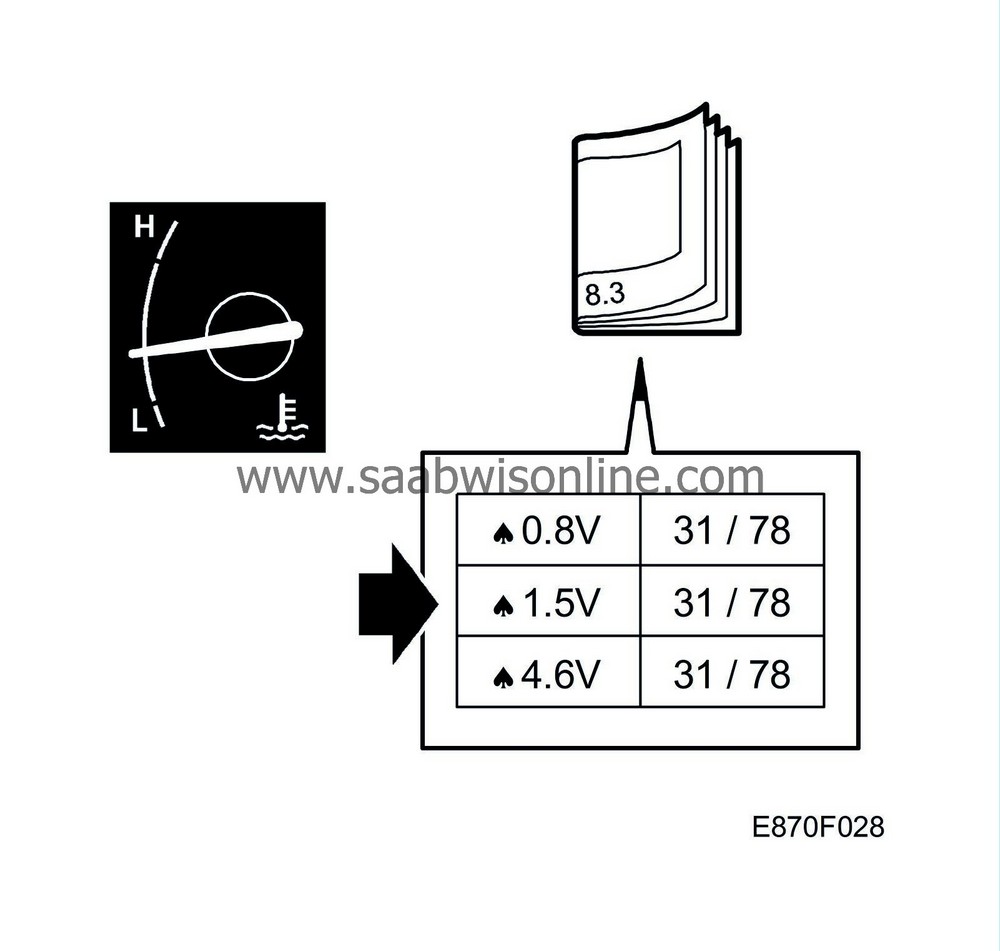
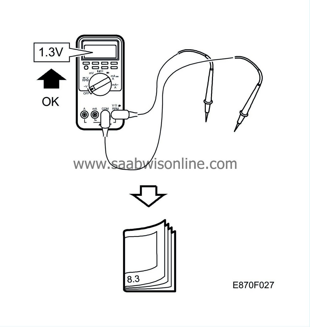
Note the test conditions. Use common sense when assessing the test result.
|
|
| • |
First check that the control module is supplied with current and is grounded.
Then check all sensor inputs and signals from other systems. Finally, check the control module outputs. Remember that the test readings do not indicate whether the actuator is working. |
|
| • |
If any reading is not OK, consult the wiring diagram to trace the leads, connectors or components which should be checked more thoroughly.
|
|
| • |
The test readings given apply to a calibrated Fluke 88/97.
|
|
| • |
The test values indicate the pulse ratio and pulse length of the signal respectively. A test instrument for measuring pulse ratio and pulse width respectively must be used.
|
|

| MCC unit, control module connections |
> = greater than; < = less than; ~ = alternating current (LP: LOGIC PROBE P = select pulse = visible pulses).
| pin nr. | Cable colour | Component/function | In/Out | Test conditions | Between X and Y | Test reading | |
|
1
|
BK
|
Control module ground
|
In
|
|
4-1
|
B+
|
|
|
2
|
RD/WH
|
Air recirculation motor power supply
|
Out
|
Activate fresh air
|
2-21
|
+12V for approx. 10s
|
|
|
Activate air recirculation
|
2-21
|
-12V for approx. 10s
|
|||||
|
3
|
|
Parking heater connection
|
In
|
Activated parking heater
|
3-1
|
B+
|
|
|
4
|
BU/RD
|
Power supply +15
|
In
|
Ignition ON
|
4-1
|
B+
|
|
|
5
|
BU/WH
|
Guide lights for buttons
|
In
|
Ignition ON
|
5-1
|
B+
|
|
|
6
|
GN/YE
|
Stepping motor, mixed-air, LH
|
Out
|
Ignition ON calibrate
|
6-25
|
50 Hz/ 50% LP Hi-Lo
|
|
|
7
|
YE/BN
|
Stepping motor, mixed-air, LH
|
Out
|
Ignition ON calibrate
|
7-26
|
50 Hz/ 50% LP Hi-Lo
|
|
|
8
|
RD/WH
|
Stepping motor, air distribution flap
|
Out
|
Ignition ON calibrate
|
8-27
|
50 Hz/ 50% LP Hi-Lo
|
|
|
9
|
RD/BU
|
Stepping motor, air distribution flap
|
Out
|
Ignition ON calibrate
|
9-28
|
50 Hz/ 50% LP Hi-Lo
|
|
|
10
|
WH/BK
|
Stepping motor, mixed-air, RH
|
Out
|
Ignition ON calibrate
|
10-29
|
50 Hz/ 50% LP Hi-Lo
|
|
|
11
|
RD/BU
|
Stepping motor, mixed-air, RH
|
Out
|
Ignition ON calibrate
|
11 - 30
|
50 Hz/ 50% LP Hi-Lo
|
|
|
12
|
|
No connection
|
|
|
|
|
|
|
13
|
OG/WH
|
Power supply fan control module
|
Out
|
Ignition ON
|
13-35
|
B+
|
|
|
14
|
GN/BU
|
Fan control module voltage
|
Out
|
Ignition ON change fan speed
|
14-1
|
0-5 V
|
|
|
15
|
GN/WH
|
A/C request
|
Out
|
Ignition ON Press in A/C button
|
15-1
|
B+
|
|
|
16
|
GN/YE
|
Electrically heated rear window request
|
Out
|
Ignition ON Press button for heated rear window
|
16-1
|
B+
for 0.2 s |
|
|
17
|
BU/WH
|
LED heated rear window on, from DICE
|
In
|
Ignition ON, DICE engages relay, see DICE for inhibitor conditions
|
4-17
|
B+
|
|
|
18-20
|
|
No connection
|
|||||
|
21
|
GN/WH
|
Air recirculation motor power supply
|
Out
|
Activate air recirculation
|
21-2
|
+12V for approx. 10s
|
|
|
Activate fresh air
|
21-2
|
-12V for approx. 10s
|
|||||
|
22
|
RD
|
Power supply +30
|
In
|
Power supply +30
|
22-1
|
B+
|
|
|
23
|
No connection
|
|
|
|
|||
|
24
|
WT/GN
|
Heat exchanger shut-off valve
|
Out
|
Ignition ON Turn both controls to max cooling
|
4-24
|
B+
|
|
|
25
|
VT/WH
|
Stepping motor, mixed-air, LH
|
Out
|
Ignition ON
Select max cold both zones |
25-6
|
50 Hz/ 50 %
LP Hi-Lo |
|
|
26
|
YE/WH
|
Stepping motor, mixed-air, LH
|
Out
|
Ignition ON
Select max cold both zones |
26-7
|
50 Hz/ 50 %
LP Hi-Lo |
|
|
27
|
WH/YE
|
Stepping motor, air distribution flap
|
Out
|
Ignition ON
Select defrost/ventilation for both zones |
27-8
|
50 Hz/ 50 %
LP Hi-Lo |
|
|
28
|
RD/VT
|
Stepping motor, air distribution flap
|
Out
|
Ignition ON
Select defrost/ventilation for both zones |
28-9
|
50 Hz/ 50 %
LP Hi-Lo |
|
|
29
|
WH
|
Stepping motor, mixed-air, RH
|
Out
|
Ignition ON
Select max cold both zones |
29-10
|
50 Hz/ 50 %
LP Hi-Lo |
|
|
30
|
BK/VT
|
Stepping motor, mixed-air, RH
|
Out
|
Ignition ON
Select max cold both zones |
30-11
|
50 Hz/ 50 %
LP Hi-Lo |
|
|
31-34
|
|
No connection
|
|
|
|
|
|
|
35
|
WH/GN
|
Fan control module reference ground
|
In
|
Ignition ON
|
35-4
|
B+
|
|
|
36-39
|
|
No connection
|
|||||


