
Test readings, control module connections
| Test readings, control module connections |
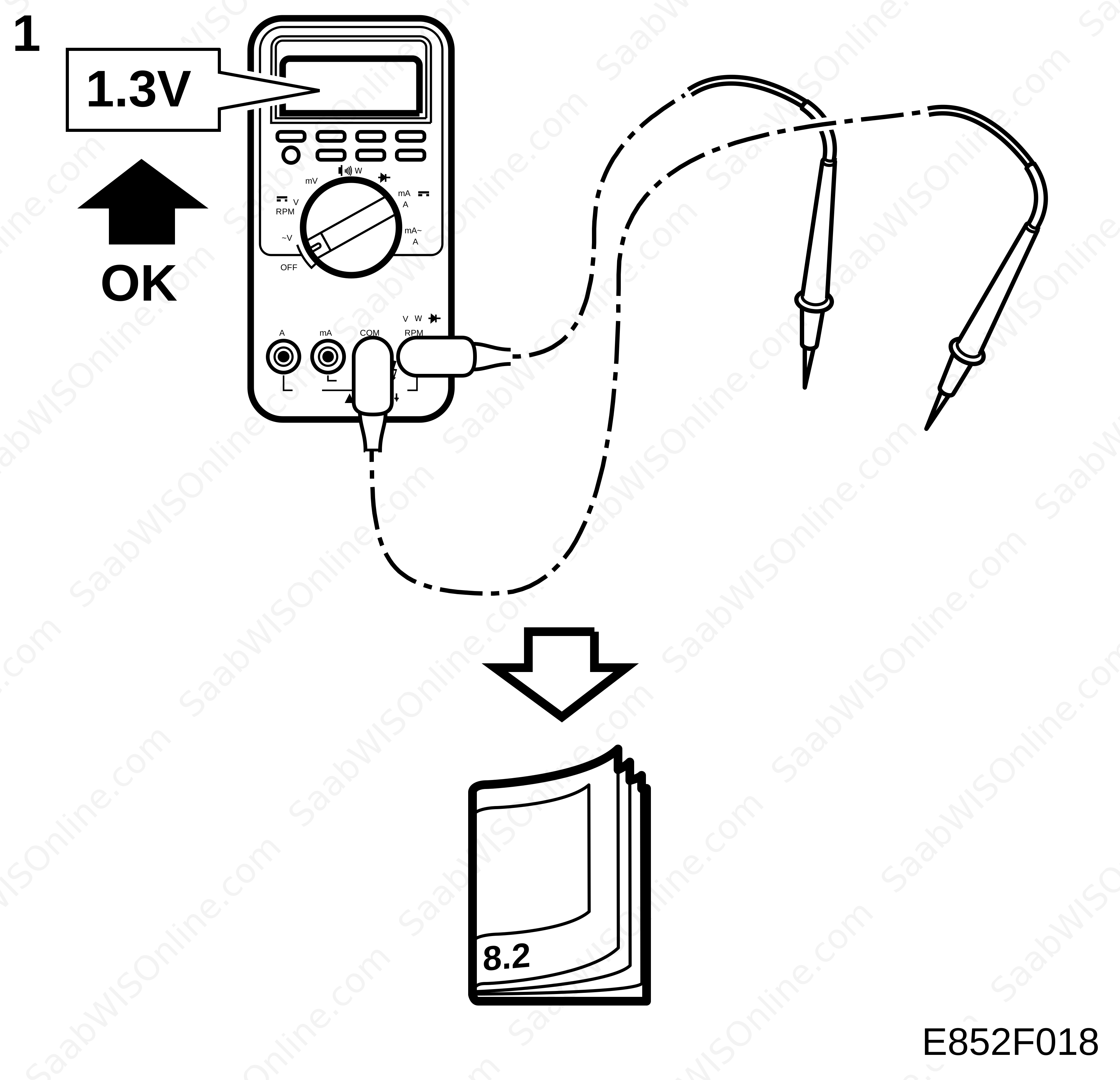
| Remember: |
| • |
Observe the test conditions. Use common sense when evaluating test results.
|
|
| • |
Unless otherwise stated, the test readings presented are with the ignition switch in the ON position.
|
|
| • |
Check the following points:
|
|
| - |
First check that the control module is supplied with current and grounded.
|
| - |
Then check all sensor inputs and signals from other systems.
|
| - |
Check the control module outputs last. Remember that the test readings do not indicate whether or not the actuator is working.
|
| • |
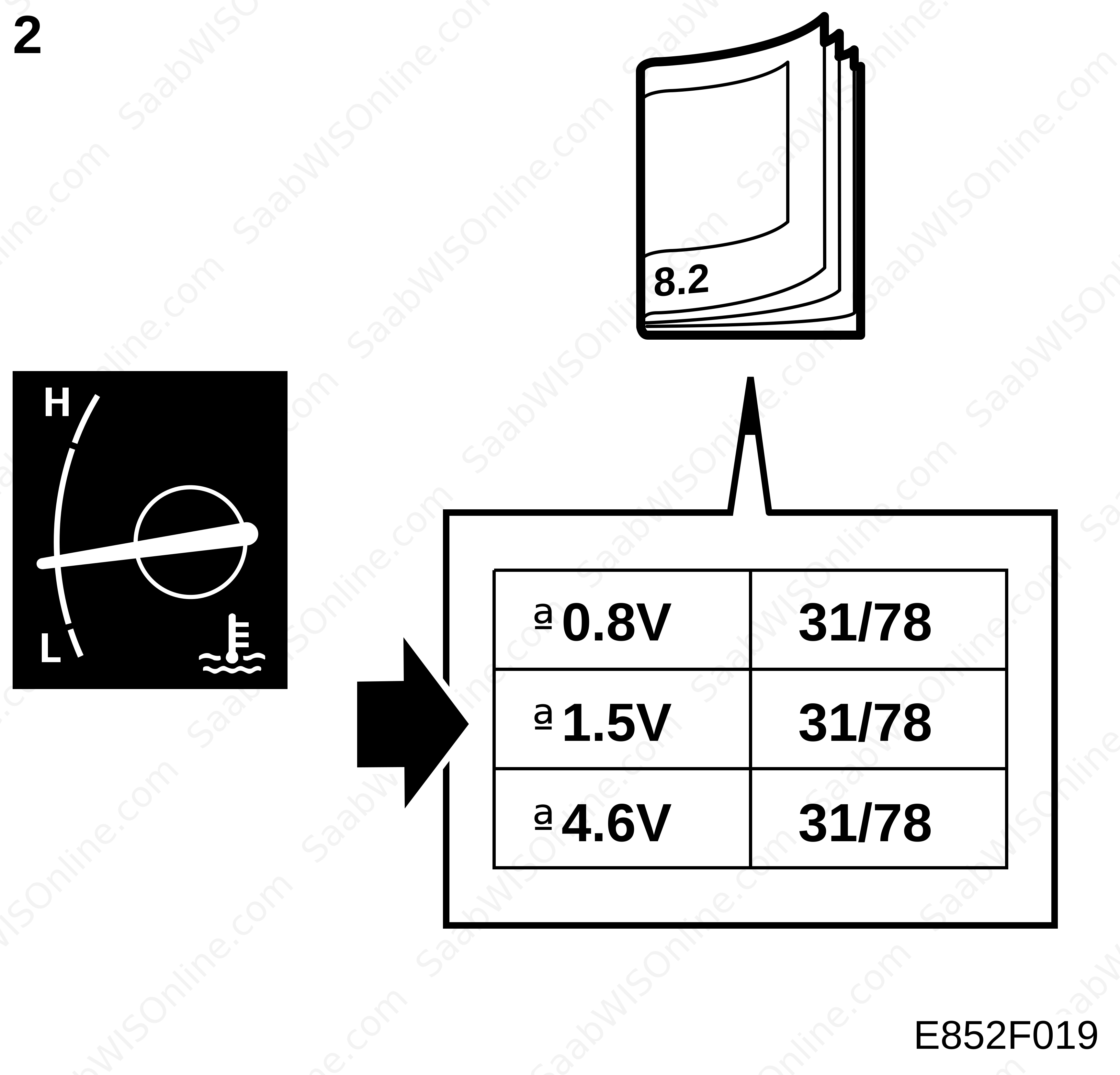
If any reading is not OK, consult the wiring diagram to trace the leads, connectors or components which ought to be checked more thoroughly.
|
|
| • |
The test readings given apply to a correctly calibrated Fluke 88/97.
|
|
| • |
The test readings show the pulse ratio and pulse duration of the signal. A test instrument capable of measuring both pulse ratio and pulse duration must be used.
|
|
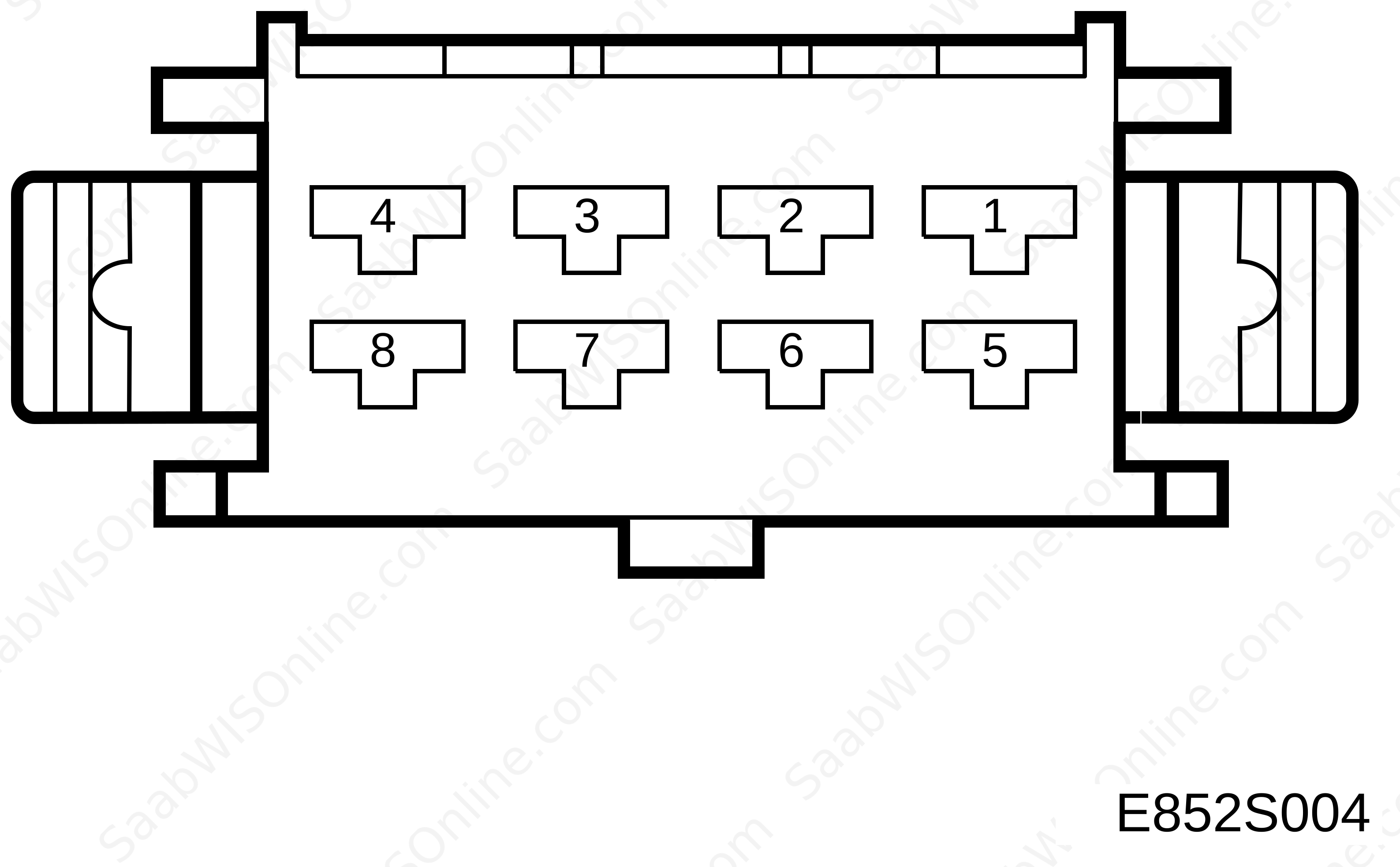
| Connector 1 (K1), test readings |
| Pin | Pin no. BOB | Component/function | I nput/Output | Test conditions | Between X and Y | Measurement value (V) |
|
1
|
1
|
Power supply (+15 circuit)
|
Out
|
|
1-7
|
B+
|
|
2-3
|
2-3
|
|
|
|
|
|
|
4
|
4
|
I-bus (+)
|
In/Out
|
Ignition ON
|
4-7
|
2-3
|
|
5
|
5
|
|
|
|
|
|
|
6
|
6
|
Power supply +30
|
In
|
6-7
|
B+
|
|
|
7
|
7
|
Ground
|
In
|
|
7-fuse ground
|
<0,5
|
|
8
|
8
|
I-bus (-)
|
Ignition ON
|
8-7
|
2-3
|
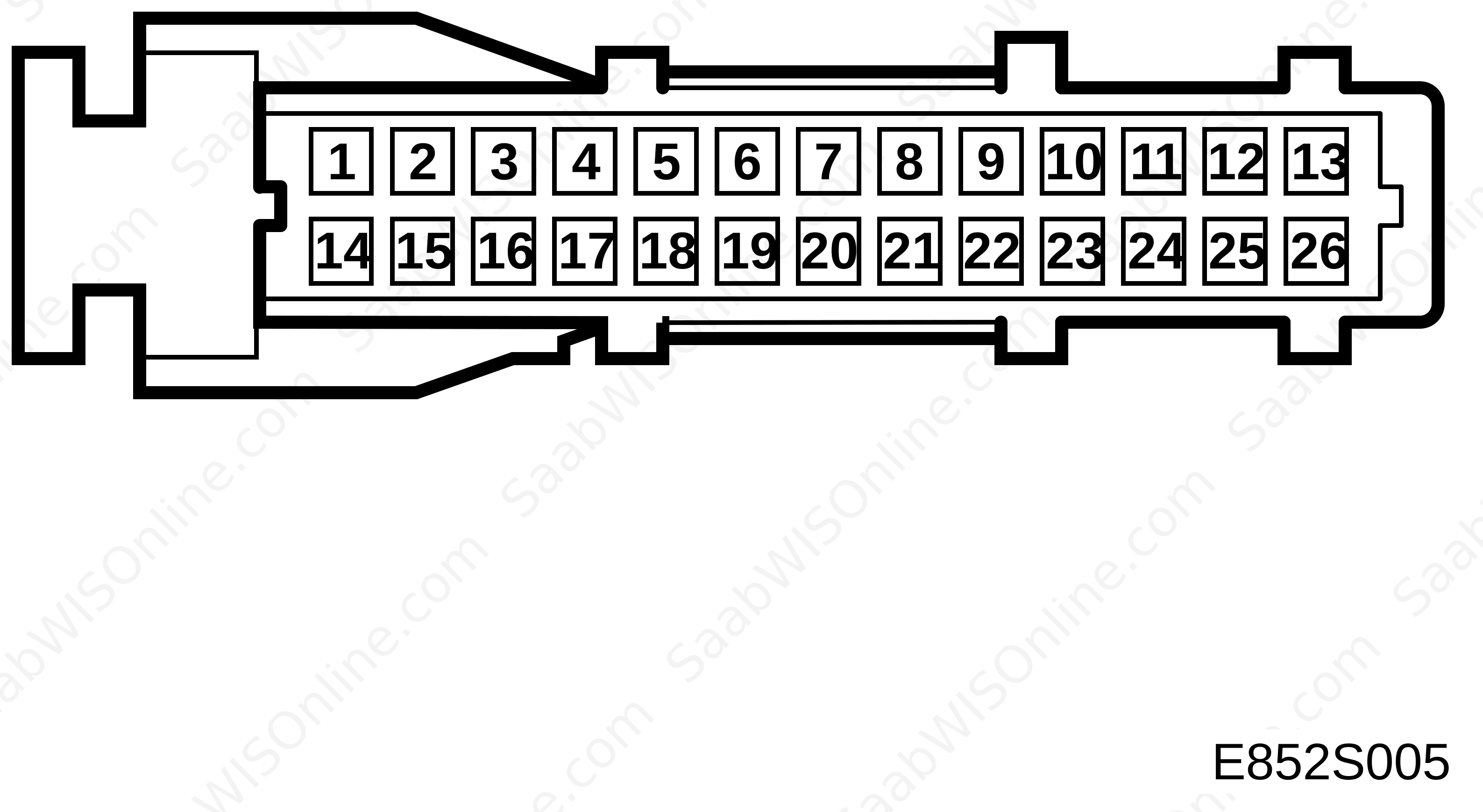
| Connector 2 (K2), test readings |
| Pin | Pin no. BOB | Component/function | I nput/Output | Test conditions | Between X and Y | Measurement value (V) |
|
1
|
9
|
Power supply of switch
|
Out
|
Ignition ON
|
1-7(K1)
|
B+
|
|
2
|
10
|
Memory button 1
|
In
|
Button in neutral
Button depressed (Ignition ON) |
2-7(K1)
|
0
B+ |
|
3
|
11
|
Memory button 2
|
In
|
Button in neutral
Button depressed (Ignition ON) |
3-7(K1)
|
0
B+ |
|
4
|
12
|
Memory button 3
|
In
|
Button in neutral
Button depressed (Ignition ON) |
4-7(K1)
|
0
B+ |
|
5-17
|
13-25
|
|
|
|
|
|
|
18
|
26
|
Memory store button
|
In
|
Button in neutral
Button depressed (Ignition ON) |
18-7(K1)
|
0
B+ |
|
19
|
27
|
Switch, seat forward
|
In
|
Button in neutral
Button depressed (Ignition ON) |
19-7(K1)
|
0
B+ |
|
20
|
28
|
Switch, seat rearward
|
In
|
Button in neutral
Button depressed (Ignition ON) |
20-7(K1)
|
0
B+ |
|
21
|
29
|
Switch, backrest forward
|
In
|
Button in neutral
Button depressed (Ignition ON) |
21-7(K1)
|
0
B+ |
|
22
|
30
|
Switch, backrest rearward
|
In
|
Button in neutral
Button depressed (Ignition ON) |
22-7(K1)
|
0
B+ |
|
23
|
31
|
Switch, front edge up
|
In
|
Button in neutral
Button depressed (Ignition ON) |
23-7(K1)
|
0
B+ |
|
24
|
32
|
Switch, front edge down
|
In
|
Button in neutral
Button depressed (Ignition ON) |
24-7(K1)
|
0
B+ |
|
25
|
33
|
Switch, rear edge up
|
In
|
Button in neutral
Button depressed (Ignition ON) |
25-7(K1)
|
0
B+ |
|
26
|
34
|
Switch, rear edge down
|
In
|
Button in neutral
Button depressed (Ignition ON) |
26-7(K1)
|
0
B+ |
| Connector 3 (K3), test readings |

| Pin | Pin no. BOB | Component/function | I nput/Output | Test conditions | Between X and Y | Measurement value (V) |
|
1
|
35
|
Ground, Hall sensor / seat front/rear
|
In
|
Ignition ON
|
1-7(K1)
|
< 0,5
|
|
2
|
36
|
Hall sensor / seat front/rear
|
In
|
A motor is running
|
2-1
|
4-7
|
|
3
|
37
|
Ground, Hall sensor / backrest front/rear
|
In
|
Ignition ON
|
3-7(K1)
|
< 0,5
|
|
4
|
38
|
Hall sensor / backrest front/rear
|
In
|
A motor is running
|
4-3
|
4-7
|
|
5
|
39
|
Ground, Hall sensor / front edge up/down
|
In
|
Ignition ON
|
5-7(K1)
|
< 0,5
|
|
6
|
40
|
Hall sensor / front edge up/down
|
In
|
A motor is running
|
6-5
|
4-7
|
|
7
|
41
|
Ground, Hall sensor / rear edge up/down
|
In
|
Ignition ON
|
7-7(K1)
|
< 0,5
|
|
8
|
42
|
Hall sensor / rear edge up/down
|
In
|
A motor is running
|
8-7
|
4-7
|
|
9
|
43
|
|
|
|
||
|
10
|
44
|
Seat forward
|
Out
|
Button depressed
Button in neutral (Ignition ON) |
10-7(K1)
|
B+
0 |
|
11
|
45
|
|
|
|
|
|
|
12
|
46
|
Front edge up
|
Out
|
Button depressed
Button in neutral (Ignition ON) |
12-7(K1)
|
B+
0 |
|
13-14
|
47-48
|
|
|
|
||
|
15
|
49
|
Seat rearward
|
Out
|
Button depressed
Button in neutral (Ignition ON) |
15-7(K1)
|
B+
0 |
|
16
|
50
|
|
|
|
||
|
17
|
51
|
Front edge down
|
Out
|
Button depressed
Button in neutral (Ignition ON) |
17-7(K1)
|
B+
0 |
|
18
|
52
|
|
|
|
|
|
|
19
|
53
|
Rear edge down
|
Out
|
Button depressed
Button in neutral (Ignition ON) |
19-7(K1)
|
B+
0 |
|
20
|
54
|
Rear edge up
|
Out
|
Button depressed
Button in neutral (Ignition ON) |
20-7(K1)
|
B+
0 |
|
21
|
55
|
Backrest rearward
|
Out
|
Button depressed
Button in neutral (Ignition ON) |
21-7(K1)
|
B+
0 |
|
22
|
56
|
Backrest forward
|
Out
|
Button depressed
Button in neutral (Ignition ON) |
22-7(K1)
|
B+
0 |
This project is supported by memberships and donations. If you use this site, please consider Joining SCNA and/or making a donation.
Our Friends