Front cylinder head, to fit (in car)
|
|
Front cylinder head, to fit (in car)
|
|
1.
|
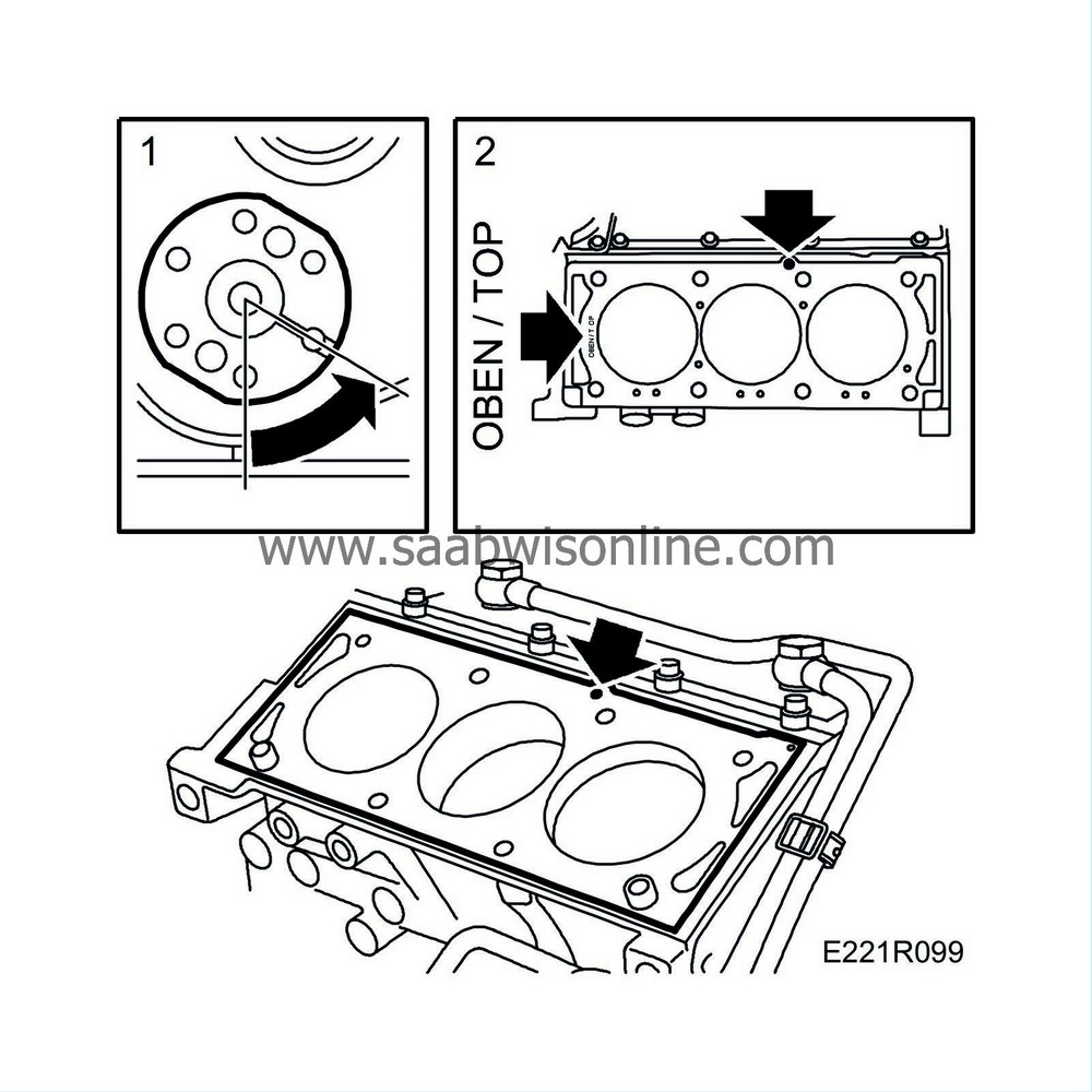
Ensure the crankshaft is at 60° BTDC.
|
|
2.
|
Clean all mating surfaces and position the gasket. Note the guides for the gasket and check that it is marked
OBEN/TOP
. Be sure to select the correct gasket for LEV engines.
|
Important
|
|
Be sure to select the correct gasket (Thinner for LEV engines)
|
|
|
|
|
4.
|
Place the cylinder head in position. Use new bolts. Tighten in the order shown.
Tightening torques:
Step I: 25 Nm (18.5 lbf ft)
Step II: Tighten a further 90°
Step III: Tighten a further 90°
Step IV: Tighten a further 90°
|
|
5.
|
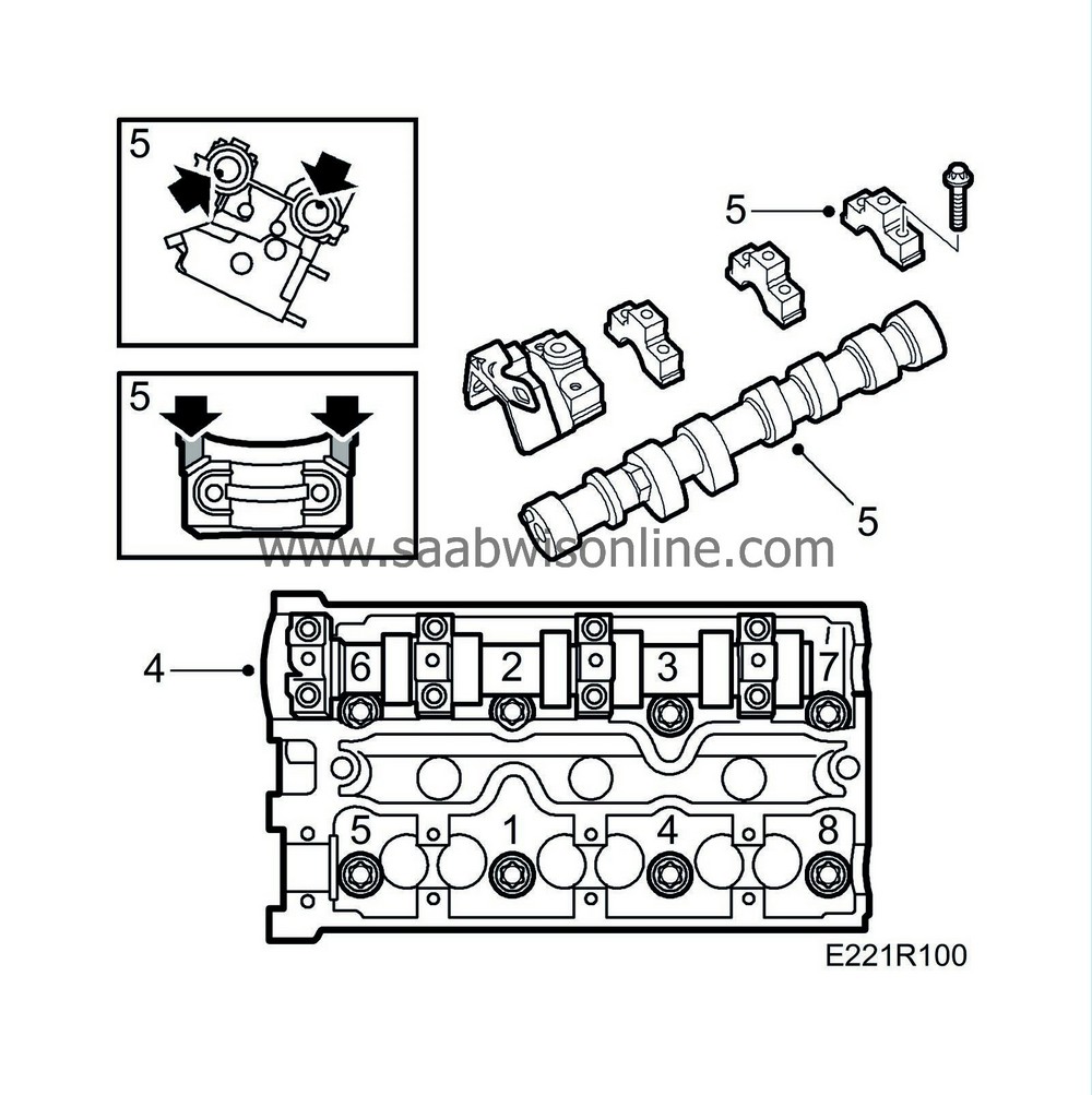
Place the exhaust camshaft in position. Check that it is placed correctly. Lubricate generously with oil.
Cylinders 2-4-6 (front)
The locating pins for the intake camshaft should be in line (downwards) with the inside bolts for the camshaft bearing caps.
The guide pin for the exhaust camshaft should point straight up from the plane of the cylinder head.
Take note of the markings on the bearing cap and cylinder head. Apply a very thin layer of
74 96 268 Thread locking adhesive
to the front contact surface of the bearing cap with the cylinder head. See illustration.
Fit the stuffing box and bearing caps and tighten the bolts. Tighten them in steps of 1/2 to 1 turn.
Tightening torque: 8 Nm (6 lbf ft)
|
|
6.
|
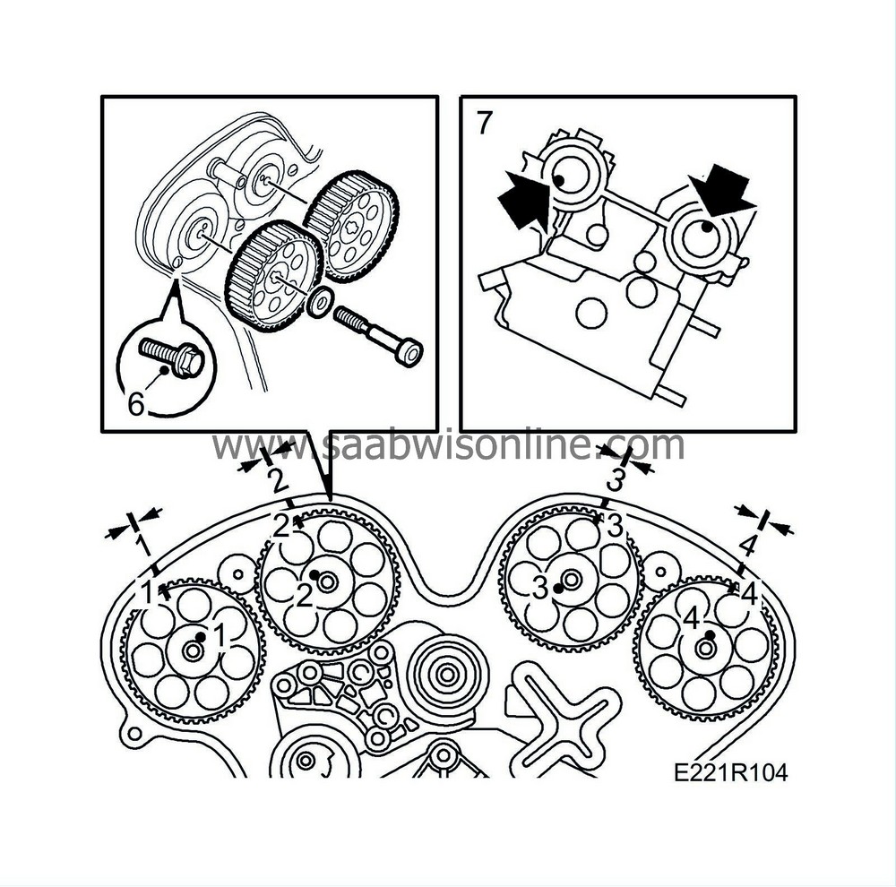
Fit the inner (rear) timing cover.
|
|
7.
|
Fit the camshaft sprockets correctly in relation to the locating pins. Check the position against the markings in the timing cover.
The number in the sprocket hub should match the number on the camshaft.
Tightening torque: 50 Nm (37 lbf ft) + 60°
 Warning
|
|
The jaws of the open-ended spanner used as a counterstay when fitting the camshaft sprockets must not be too long. There is otherwise a risk of damaging the metal so that the tappets become locked.
|
|
|
|
|
|
|
|
8.
|
Check that the O-rings are in place in the camshaft cover and wipe clean. Lubricate with a soap solution and place part No. (10) 81 52 381 in the corners at the camshaft bearing caps.
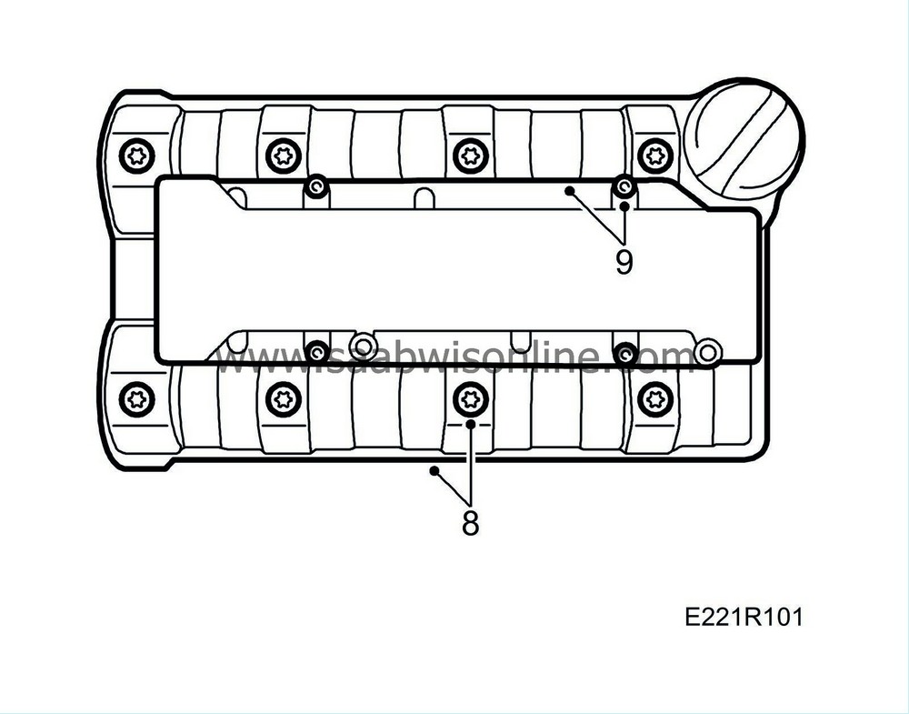
Tightening torque: 8 Nm (6 lbf ft)
|
|
9.
|
Fit the ignition discharge module.
|
|
10.
|
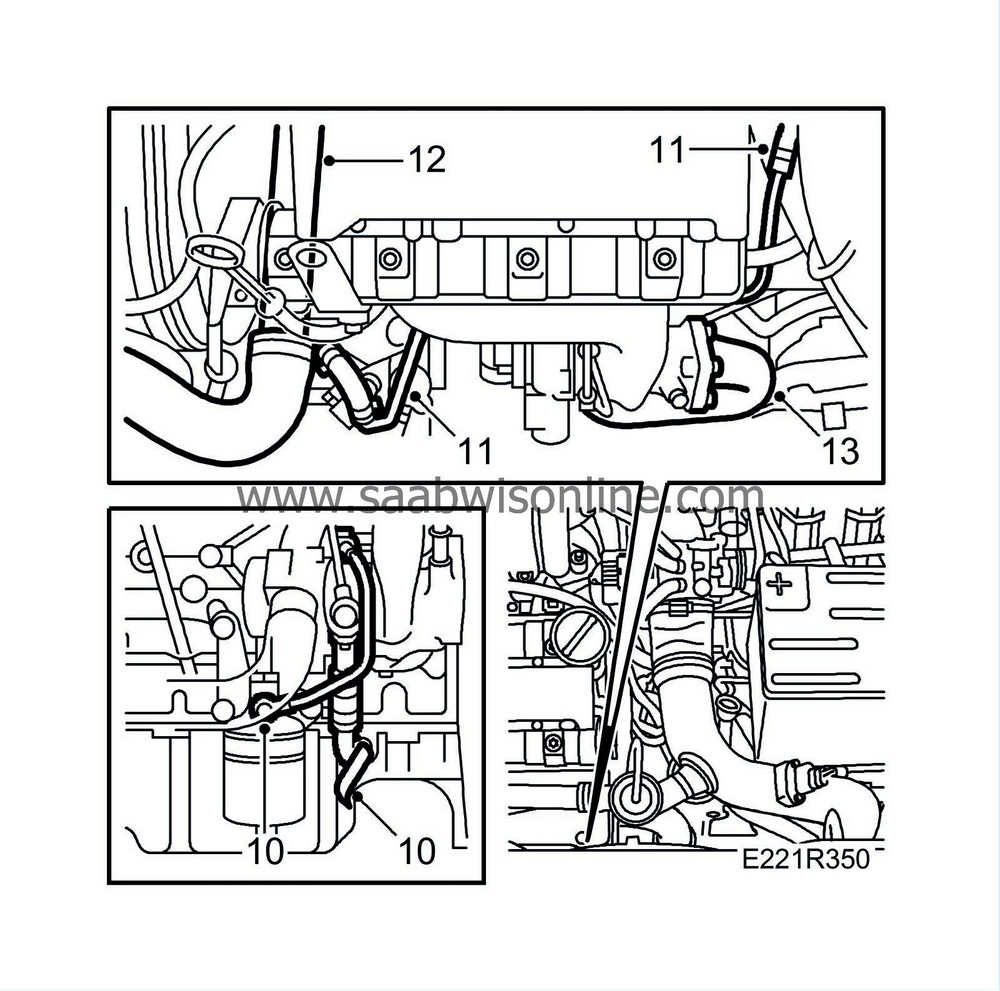
Fit the turbo oil pipes.
Tightening torques:
Oil pipe, turbo: 20 Nm (15 lbf ft)
Oil pipe, oil filter adapter: 20 Nm (18.5 lbf ft)
Oil return pipe: 14 Nm (10 lbf ft)
|
|
11.
|
Fit the turbo's water pipes.
Tightening torques:
Water pipe: 25 Nm (18.5 lbf ft)
Cylinder head retaining bolt 14 Nm (10 lbf ft)
|
|
12.
|
Connect the water hose to the thermostat housing.
|
|
13.
|
Fit the front exhaust pipe to the turbo.
Tightening torque: 24 Nm (18 lbf ft)
|
Important
|
|
To reduce the risk of hoses mounted on the delivery side of the turbocharger coming loose due to low friction at high air pressure, the hoses and connecting pieces must be cleaned thoroughly before fitting. Use a rag dampened with 93 160 907 Motip Dupli cleaning agent to wipe clean inside the ends of the hoses. Clean the connecting pieces as well. If hose clips are rusty or damaged, they must be replaced so the correct clamping force is maintained.
|
|
|
|
|
14.
|
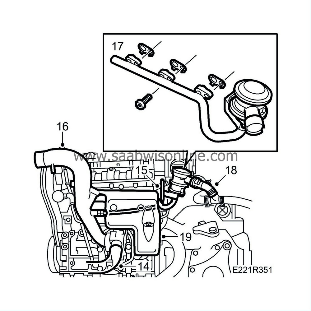
Fit the hose between the turbo and the charge air cooler.
|
|
15.
|
Fit the crankcase breather pipe to the turbo intake pipe. Note the gasket.
Tightening torque: 24 Nm (18 lbf ft)
|
|
16.
|
Fit the turbo's intake pipe.
Tightening torques:
V-clamp: 3 Nm (2.2 lbf ft)
U-clamp, cylinder head 14 Nm (10.3 lbf ft)
|
|
17.
|
Fit the SAI pipe using new gaskets to the front exhaust manifold.
|
|
18.
|
Fit the hose connection to the valve; check the connection.
|
|
19.
|
Fit the crankcase ventilation pipe between the cylinder head and the turbo intake pipe. Connect the hose from the oil trap.
Tightening torque: Banjo screw, intake pipe 24 Nm (17.7 lbf ft)
|
|
20.
|
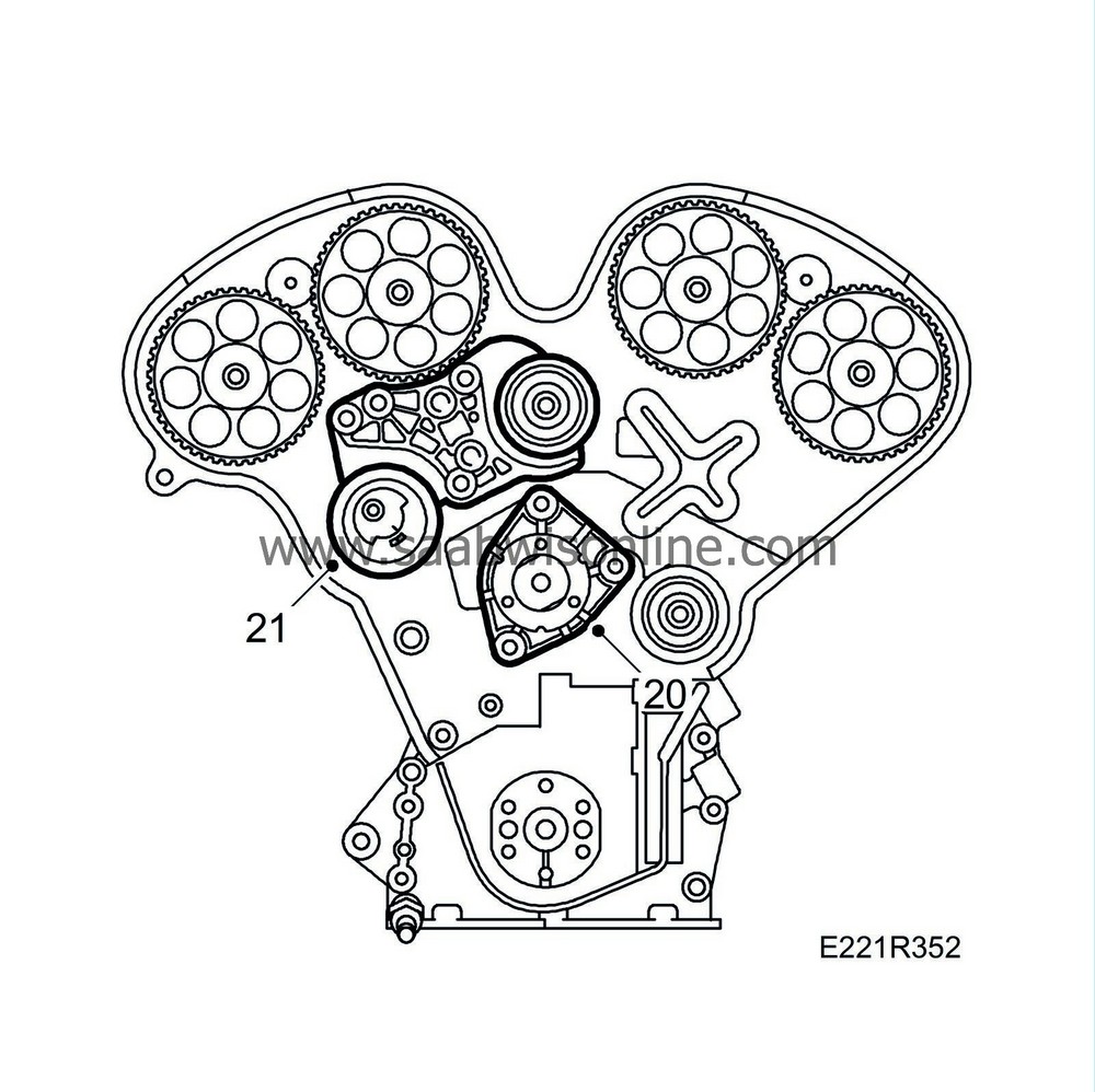
Fit the coolant pump.
Tightening torque 25 Nm (18.5 lbf ft)
|
|
21.
|
Fit the bracket with tensioning roller and the upper adjuster roller.
|
|
23.
|
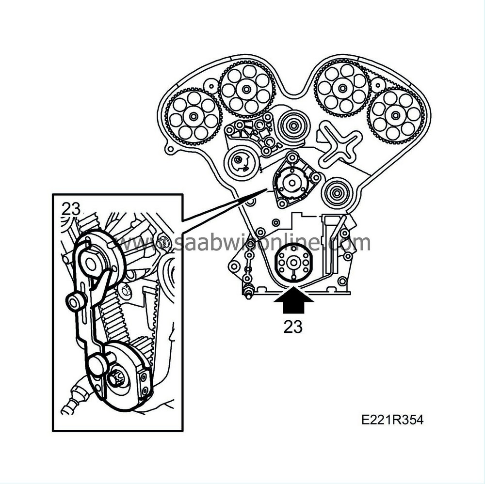
Rotate the crankshaft to just before the 0° mark and fit tool KM-800-10. Carefully rotate the crankshaft in the direction of rotation of the engine until the arm is lying against the coolant pump flange and remove the tool.
|
|
24.
|
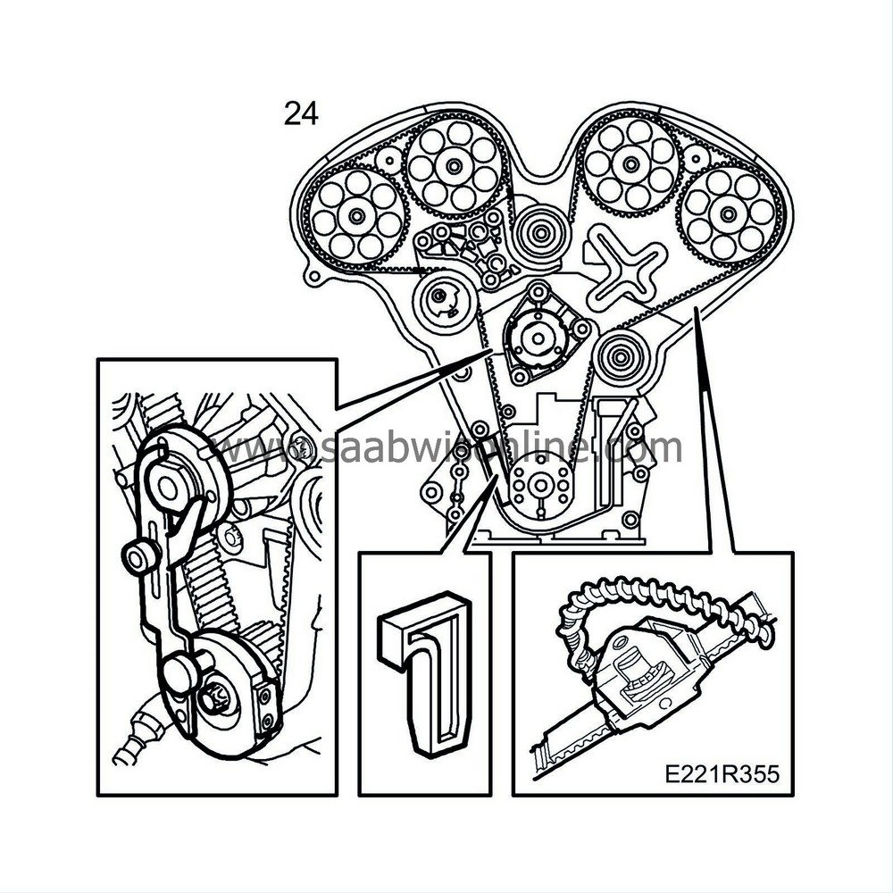
Refitting a marked timing belt:
Fit the timing belt in accordance with the marking on the belt and the marked direction of rotation. Use
83 95 006 Adjustment tools, cam sprocket and timing belt, V6
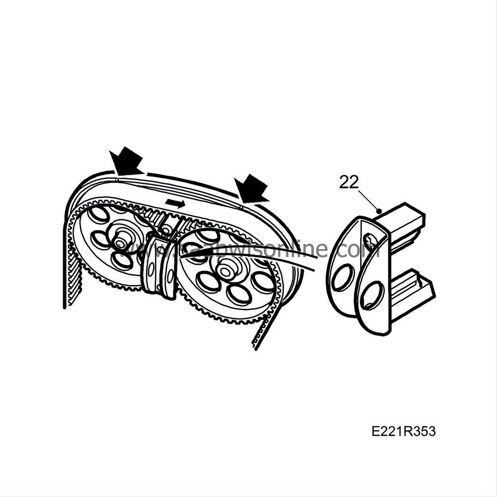
KM-800-30 in order to hold the belt in place. Fit the lower guide roller. Make sure that the washer is fitted correctly. Carefully check that the markings on the timing belt are aligned with the corresponding markings on the camshaft sprocket. Raise the car and check the marking on the crankshaft. Lower the car and remove the tool KM-800-30.
Refitting a new unmarked timing belt:
Fit the new timing belt in accordance with the belt's direction of rotation. Use
83 95 006 Adjustment tools, cam sprocket and timing belt, V6
KM-800-30 in order to hold the belt in place. Fit the tension pulley. Make sure that the washer is fitted correctly. Carefully check that the markings are aligned with the camshaft sprockets. Remove the tool KM-800-30.
Fit locking tool KM-800-10, mount a length of the timing belt and fit
Belt tension gauge
, part no. 83 93 985, to measure the belt tension.
Tighten the centre bolts of the adjuster rollers lightly. Adjust the lower adjuster roller anticlockwise until a tension of 275-300 Nm is obtained. Use tool 83 94 983. Tighten the adjuster roller's bolt. Use tool 83 94 983 as a counterstay. Check the belt tension again and adjust as necessary.
Tightening torque: 40 Nm (30 lbf ft)
Remove the belt tension gauge and piece of timing belt.
|
Important
|
|
Adjustment of belt tension is only a preparatory measure and must not be used as a check when the belt is finally adjusted.
|
|
|
|
|
25.
|
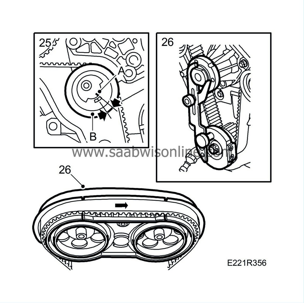
Ensure the adjusting nut on the upper adjusting roller rotates freely and is not tight. Adjust the tension pulley with a 5 mm Allen key until the two lines on the tension pulley correspond with each other. Tighten.
Tightening torque: 20 Nm (15 lbf ft)
Remove the locking tool for camshaft sprockets 1 and 2. Fit tool KM-800-20. Then, adjust the upper adjusting roller anticlockwise with tool 83 94 983 until the markings on the camshaft sprocket are aligned with the corresponding markings on KM-800-20. Tighten. Use tool 83 94 983 as a counterstay.
Tightening torque: 40 Nm (30 lbf ft)
Remove KM-800-20 and the other locking tools.
|
|
26.
|
Rotate the engine two revolutions in the direction of rotation until just before the zero mark and fit locking tool KM-800-10 on the crankshaft. Carefully rotate the crankshaft in the direction of rotation of the engine until the arm is lying against the coolant pump and tighten it. Fit tool KM-800-20 and ensure the markings on the camshaft sprocket are opposite the markings on the tool and that the edge of the belt is aligned with the edge of the sprocket.
|
Important
|
|
Check that marking A is about 2 mm above marking B. If this distance is smaller, adjustment must be carried out afresh.
|
|
|
|
|
27.
|
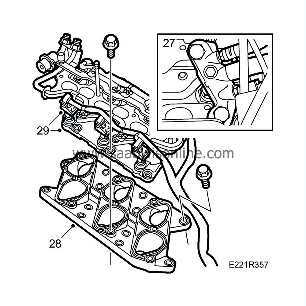
Fit the coolant bridge. Coat the bolts with (10) 74 96 284. Mind the gaskets.
Tightening torque: 30 Nm (22 lbf ft).
|
|
28.
|
Fit the lower intake manifold with new gaskets.
Tightening torque: 20 Nm (15 lbf ft)
|
|
29.
|
Fit the middle intake manifold.
Tightening torque: 20 Nm (15 lbf ft)
|
|
30.
|
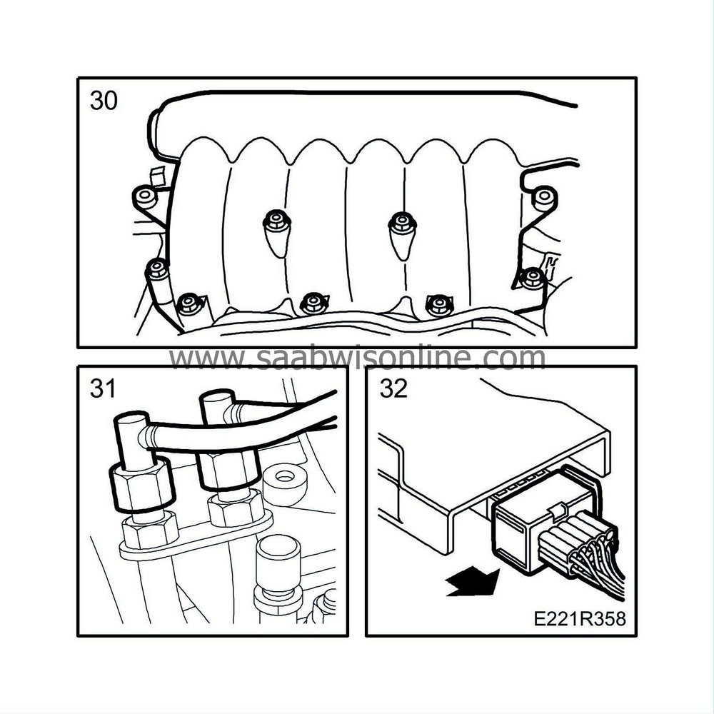
Fit the upper intake manifold with a new gasket.
Tightening torque: 20 Nm (15 lbf ft)
|
|
31.
|
Connect the fuel lines.
|
|
32.
|
Plug in the connectors for the ignition discharge module and injectors.
|
|
33.
|
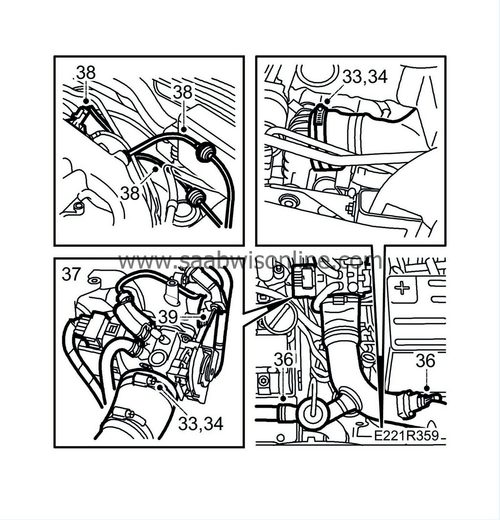
Connect the turbo delivery pipe to the throttle body.
|
|
34.
|
Raise the car, connect the turbo delivery pipe to the charge air cooler. Tighten the hose clip at the charge air cooler.
|
|
35.
|
Lower the car and tighten the hose clip at the throttle body.
|
|
36.
|
Plug in the temp/pressure sensor connector. Fit the bypass pipe with valve.
|
|
37.
|
Connect the vacuum hose and the two water hoses to the throttle body. Plug in the throttle body connector and the hose to the venting valve on the underside of the throttle body.
Tightening torques:
Bypass pipe 8 Nm (6 lbf ft)
|
|
38.
|
Connect the vacuum hoses and plug in the pressure/temperature sensor connector for the upper intake manifold.
|
|
39.
|
Refit the throttle cable.
|
|
40.
|
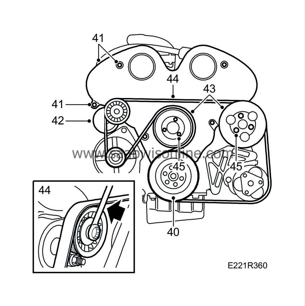
Fit the crankshaft pulley with the notch facing the projection on the engine (diagonally upwards-forwards).
Tightening torque: 20 Nm (15 lbf ft)
|
|
41.
|
Fit the timing cover.
Tightening torque: 8 Nm (6 lbf ft)
|
|
42.
|
Fit the belt tensioner and the generator air intake.
|
|
43.
|
Fit the coolant pump pulley and the power steering pump pulley. Use Loctite, part No. 74 96 292. Do not tighten the bolts.
|
|
44.
|
Fit the multigroove belt.
|
|
45.
|
Tighten the retaining bolts on the pulleys.
Tightening torques:
Belt pulley/coolant pump: 8 Nm (6 lbf ft)
Belt pulley/power steering pump: 20 Nm (15 lbf ft)
|
|
46.
|
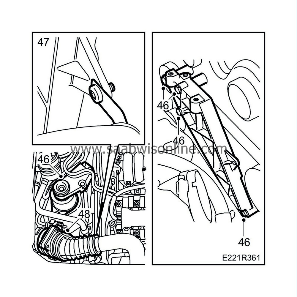
Fit the right-hand engine attachment with bracket and engine mount.
Tightening torques:
To body 63 Nm (46.5 lbf ft)
|
|
47.
|
Fit the power steering hose in the holder
|
|
48.
|
Fit the mass air flow sensor with hose.
|
|
50.
|
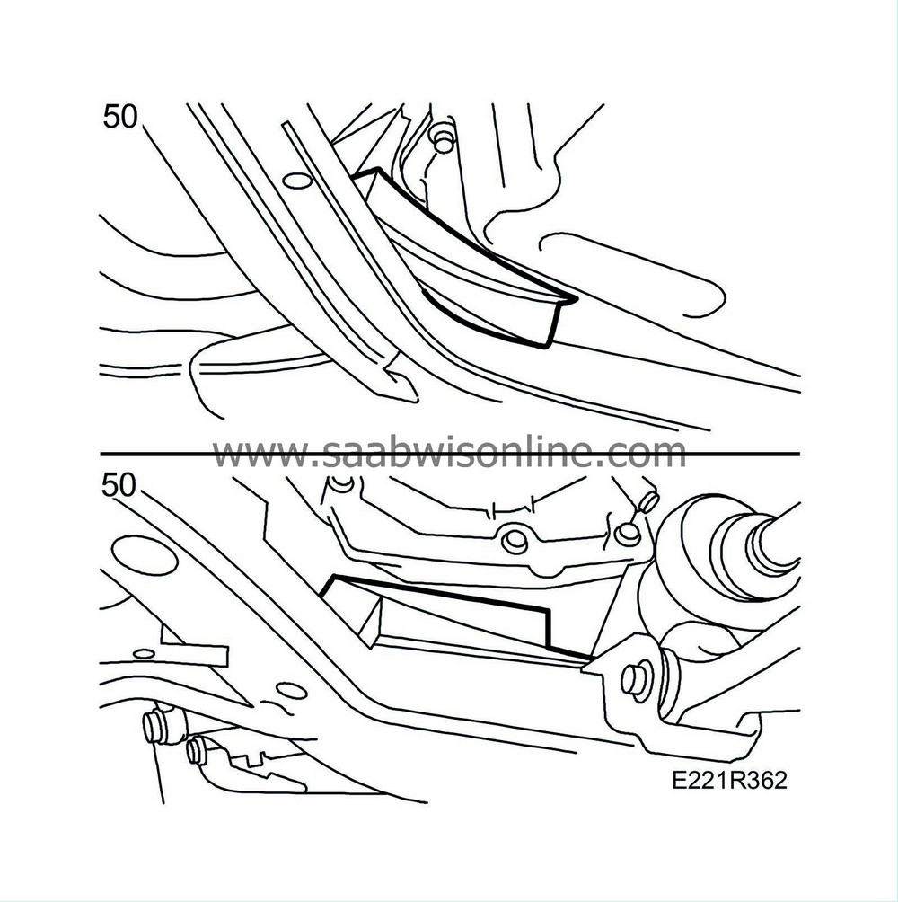
Lower the engine by carefully removing the wedges.
|
|
51.
|
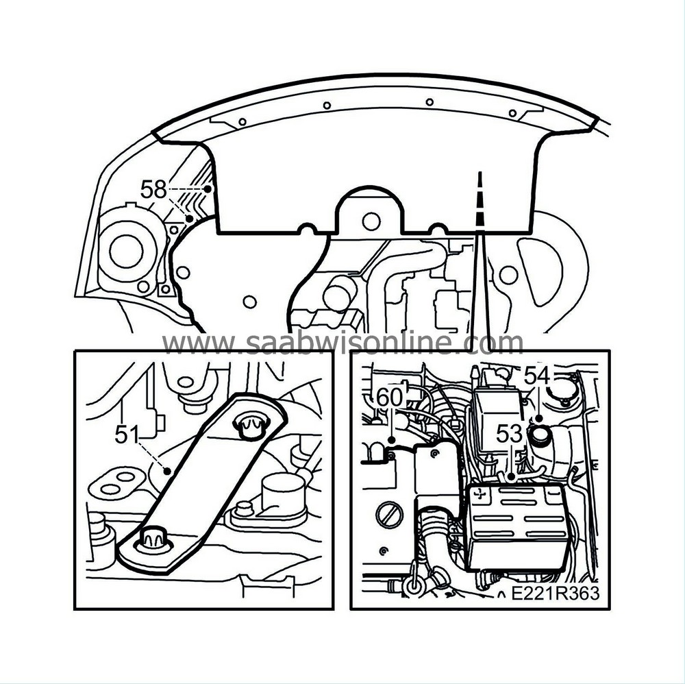
Fit the turbo bracket. Mind the protective plate for the crankshaft position sensor mounted on the same bracket.
|
|
52.
|
Lower the car to the floor.
|
|
53.
|
Fit the battery with bleeder hose.
|
|
54.
|
Fill up with coolant. Do not forget to close the radiator drain cock first. Screw on the expansion tank filler cap.
|
|
55.
|
Bleed the cooling system as follows:
Fill the system up to the MAX level, close the expansion tank filler cap, start the engine and warm it up (by running it at varying rpm) until the radiator fan starts. Unscrew the expansion tank filler cap and top up again to the MAX level. Close the filler cap and run the engine at varying rpm until the radiator fan starts three more times. Switch off the engine and top up as necessary to the MAX level.
|
Note
|
|
The A/C should be OFF.
|
|
|
58.
|
Fit the lower engine cover.
|
|
59.
|
Lower the car to the floor.
|
|
60.
|
Fit the upper engine cover and remove the wing protectors.
|
|
61.
|
Reset the clock and, where appropriate, the radio code.
|




 Warning


