Valve gear, to remove (in car)
| Valve gear, to remove (in car) |
| 1. |
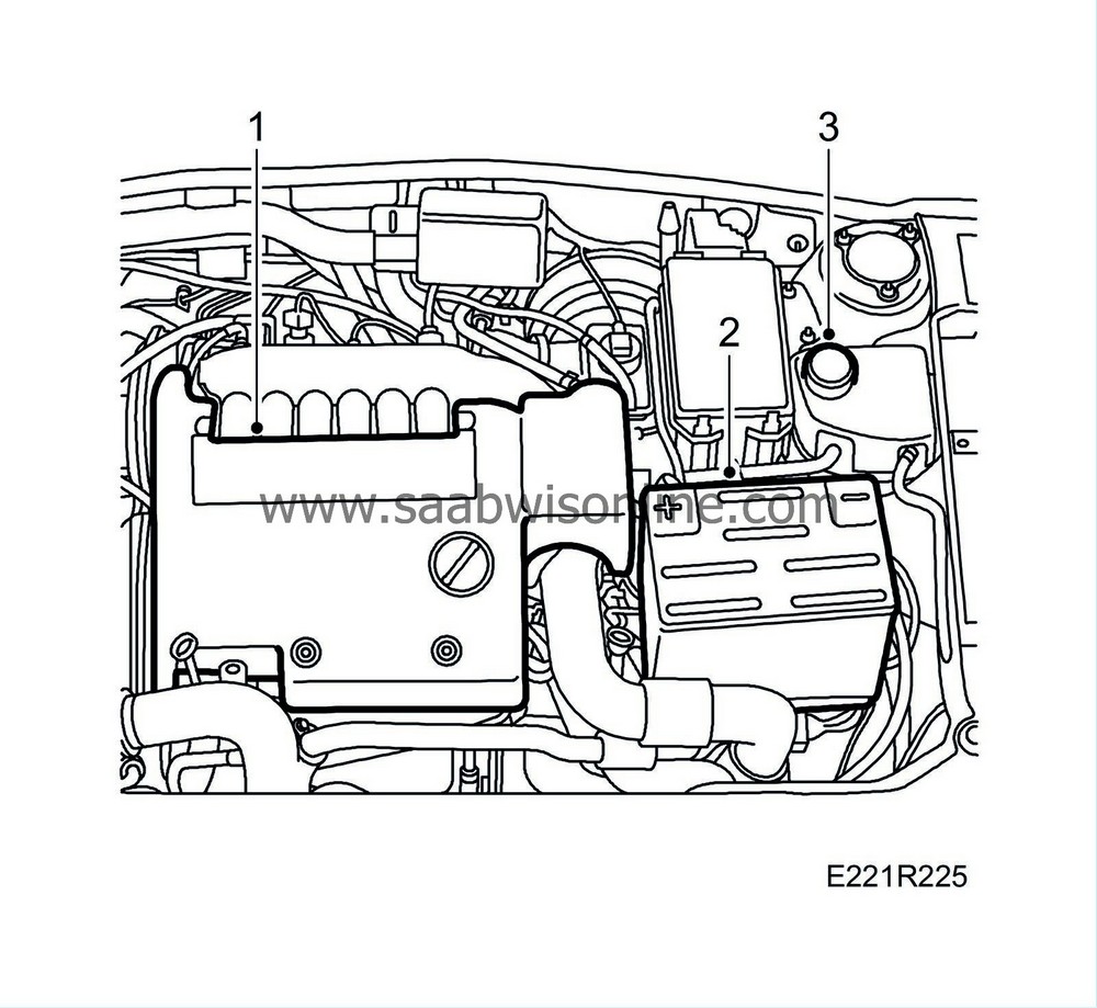
Drape the wing protectors over the wings and remove the engine cover.

|
|
| 2. |
Disconnect the negative cable from the battery.
|
|
| 3. |
Open the cap on the expansion tank and release the pressure.
|
|
| 4. |
Raise the car.
|
|
| 5. |
Remove the lower spoiler sections.

|
|
| 6. |
Drain the coolant from the radiator.
|
|
| 7. |
Insert two
83 95 238 Wedges
, between the oil sump and subframe and between the gearbox and subframe.

|
|
| 8. |
Lower the car.
|
|
| 9. |
Remove the mass air flow sensor with hose.

|
|
| 10. |
Detach the power steering hose from the holder.
|
|
| 11. |
Remove the right-hand engine attachment with bracket and engine mount.
|
|
| 12. |
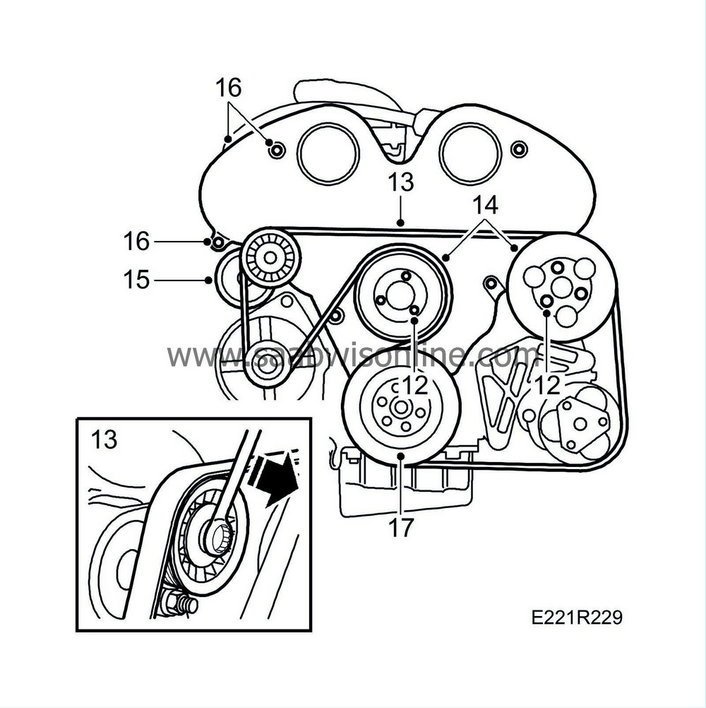
Undo the retaining bolts from the coolant pump pulley and power steering pump pulley

|
|
| 13. |
Release the multigroove belt from tension.
|
|
| 14. |
Remove the coolant pump pulley and power steering pump pulley.
|
|
| 15. |
Remove the belt tensioner and generator air intake.
|
|
| 16. |
Remove the timing cover.
|
|
| 17. |
Remove the crankshaft pulley.
|
|
| 18. |
Unhook the throttle cable.

|
|
| 19. |
Remove the vacuum hoses and unplug the pressure sensor's connector from the upper intake manifold.
|
|
| 20. |
Detach the vacuum hose and the two water hoses from the throttle. Remove the turbo pressure hose with charge air bypass pipe. Unplug the throttle's connector and detach the venting-valve hose from the underside of the throttle.
|
|
| 21. |
Unplug the connectors for the ignition discharge module and injectors.

|
|
| 22. |
Detach the fuel lines.
|
|
| 23. |
Undo the upper intake manifold and move it aside.
|
|
| 24. |
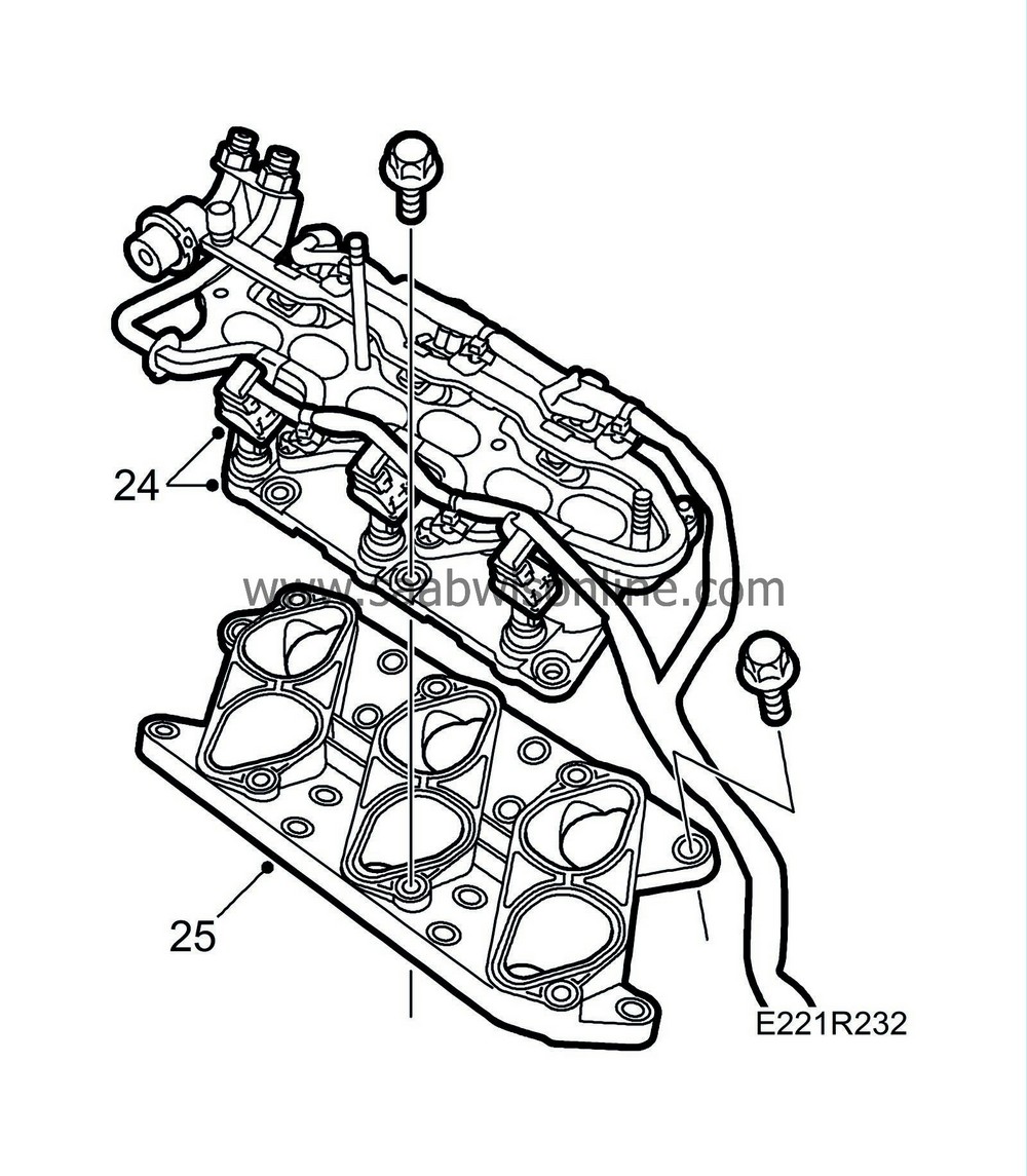
Remove the middle intake manifold.

|
|
| 25. |
Remove the lower intake manifold. Plug the holes with paper or the like.
|
|
| 26. |
Zero the engine. The markings on the camshaft sprockets and the timing cover must be aligned, use
Installation tool for camshaft sprockets and camshaft drive belt
KM-800-20, as must the crankshaft marking. Fit the locking tool KM-800-1 and KM-800-2 for the camshaft sprockets and locking tool KM-800-10 for the crankshaft.

|
|
| 27. |
Undo the tensioning pulley and adjusting rollers. Use tool 83 94 983 as a counterstay on the adjusting rollers.

|
|
| 28. |
Mark the direction of rotation on the belt. The belt can also be marked with the respective camshaft markings and crankshaft marking to facilitate refitting. Remove tool KM-800-10 from the crankshaft. Let locking tools KM-800-1 and KM-800-2 remain. Remove the lower adjusting roller. Ensure the washer behind the roller is also removed. Remove the timing belt.
|
|
| 29. |
Remove the bracket with tensioning roller and the upper adjuster roller.
|
|
| 30. |
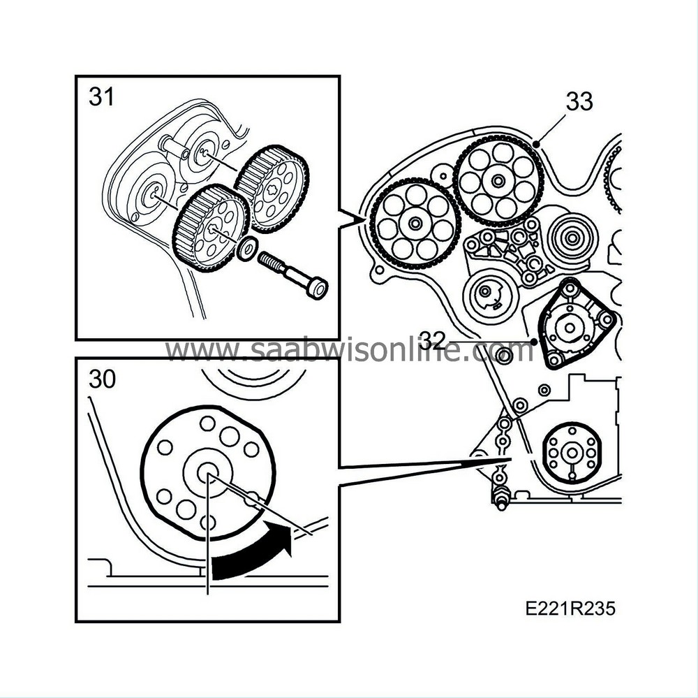
Rotate the crankshaft to 60° BTDC. Note the marking.

|
|
| 31. |
Remove the camshaft sprockets.
|
|
| 32. |
Remove the coolant pump.
|
|
| 33. |
Remove the inner timing cover.
|
|
| 34. |
Remove the ignition discharge module.

|
|
| 35. |
Remove the camshaft cover. Make sure that the O-rings are in place and that they do not fall into the engine.
|
|
| 37. |
Lift out the tappets using tool 83 91 401.
|
|
| 38. |
Fit
Protective collars
part no. 83 95 022 round the valve springs to protect the sealing surfaces of the tappets.
|
|
| 39. |
Rotate the crankshaft so the piston in the cylinder is in the upper stop position. Lock the engine with
83 94 868 Flywheel locking attachment
and unscrew the spark plug for the cylinder. Use
Spark plug socket
part no. 83 95 485 and install the
83 94 173 compressed air adapter for spark plug hole
. Connect compressed air and place the piston and valves under pressure.
|
|
| 40. |
Depress the valve heads using valve spring compressor 83 95 246 and remove the tappets.

|
|
| 41. |
Lift the spring cap and the valve spring and remove the valve stem seal with
83 94 157 Pliers for removing valve stem seal
.
|
|


