Brief description
| Brief description |
Saab Trionic T7 is an engine management system (control module) which controls the mass air flow, fuel and ignition.
When the driver presses the accelerator, the throttle cable turns the pedal position sensor mounted in the throttle body. The system requests a certain amount of torque and the throttle motor turns the throttle until the throttle position sensor value corresponds to the requested degree of torque. If necessary, the volume of charge air is also increased. The system has the following advantages:
| • |
Compensation for the turbo lag is possible.
|
|
| • |
Exhaust emissions can be reduced in connection with load changes.
|
|
| • |
The idle speed control is integrated.
|
|
| • |
Load compensation is possible throughout the entire load and speed register.
|
|
| • |
Effective torque limitation as necessary.
|
|
| • |
Cruise control can easily be integrated.
|
|
Fuel injection is sequential and controlled by the mass air flow.
Ignition takes place by means of an ignition discharge module. The spark plugs act as sensors to detect combustion and knocking. This means that neither the camshaft position sensor nor the knock sensor are required.
The Saab Trionic T7 was developed by Saab and has huge development potential.
Compared with previous Trionic systems, the following functions are new:
| Throttle body (600) |
| • |
Contains the pedal position sensor (which is turned by the throttle cable), throttle motor and throttle position sensor.
|
|
| • |
Informs the control module of the driver's torque request.
|
|
| • |
Turns the throttle to the position determined by the control module.
|
|
| Limp-home solenoid (607) |
| • |
Supplied with current via the relay, the limp-home solenoid (640) is controlled by the control module.
|
|
| • |
It provides a mechanical connection between the throttle cable and the throttle spindle if a fault occurs in the throttle body or its leads. The mechanism must be reset manually.
|
|
| Charge air absolute pressure sensor (603) |
| • |
Informs the control module of the pressure level before the throttle.
|
|
| • |
Used to determine the density of the air before the throttle.
|
|
Dense air requires a smaller throttle angle.
| Intake air temperature sensor (407) |
| • |
Informs the control module of the temperature before the throttle.
|
|
| • |
Used to determine the density of the air before the throttle.
|
|
Dense air requires a smaller throttle angle.
| Manifold absolute pressure sensor (431) |
| • |
Informs the control module of the pressure level after the throttle.
|
|
| • |
Used to correct the mass air flow sensor value when rapid load changes occur.
|
|
| Turbo bypass control valve (605) |
| • |
Connects the bypass valve control in front of the throttle.
|
|
| • |
When the accelerator pedal is released, the bypass valve control line is connected after the throttle.
|
|
Prevents noise and varying charge pressure.
| Mass air flow sensor (205) |
| • |
Sends frequency-modulated information on the mass air flow to the control module.
|
|
| • |
Acts as a main sensor for fuel injection.
|
|
| P-Bus and I-Bus |

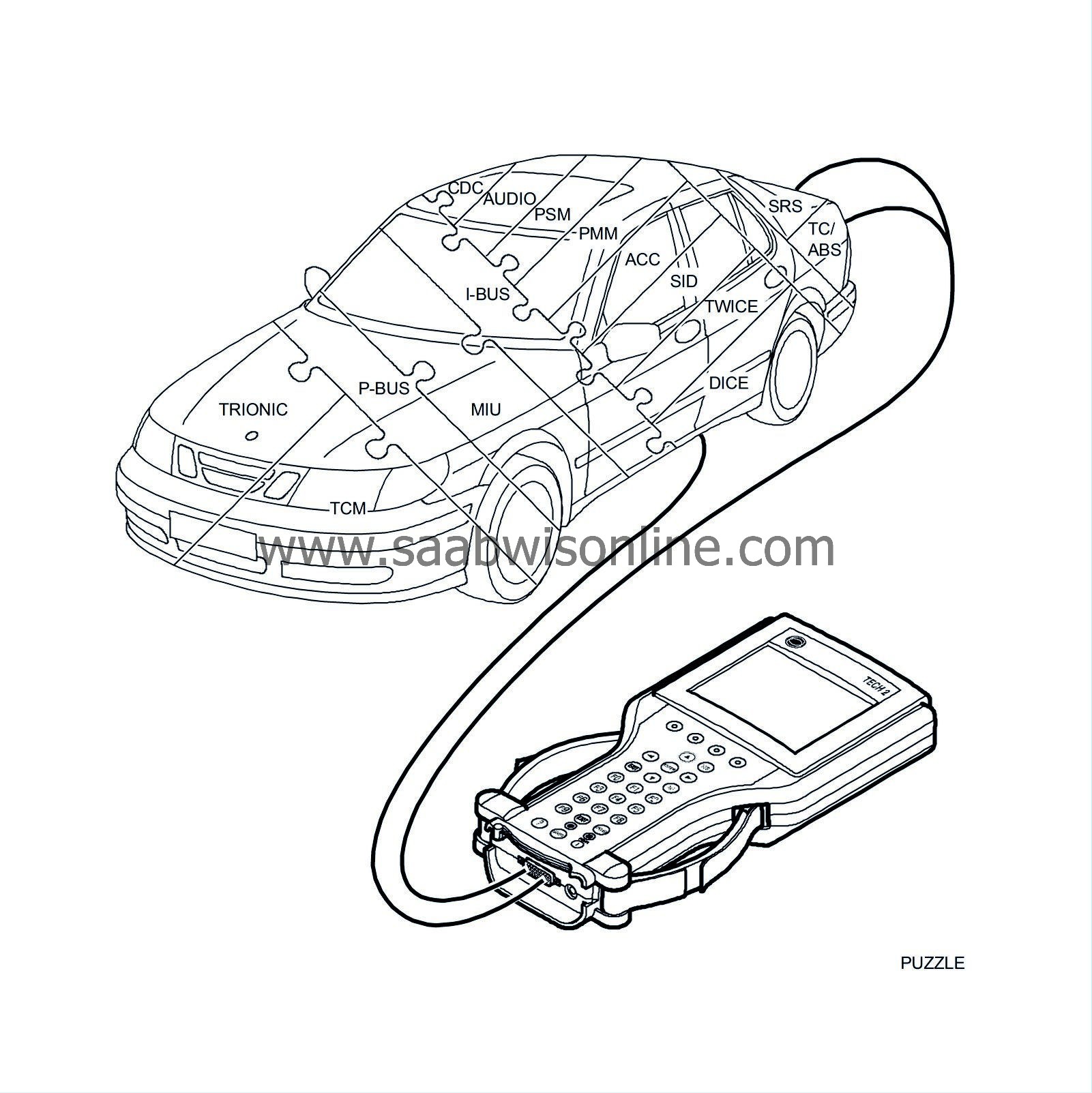
The buses are divided into the Powertrain bus (P-Bus) and the Instrument bus (I-Bus). Both buses are connected to the main instrument unit (MIU). The buses are electrically isolated from each other.
The P-Bus has a data transfer rate 10 times higher than that of the I-Bus.
All information sent out by a control module is available to all other control modules connected to the bus. The MIU ensures that the information which is available on one bus is also available on the other.


