Crankshaft position sensor
| Crankshaft position sensor |

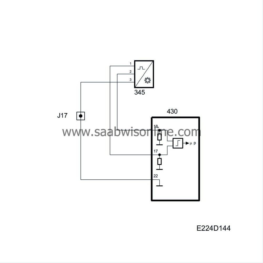
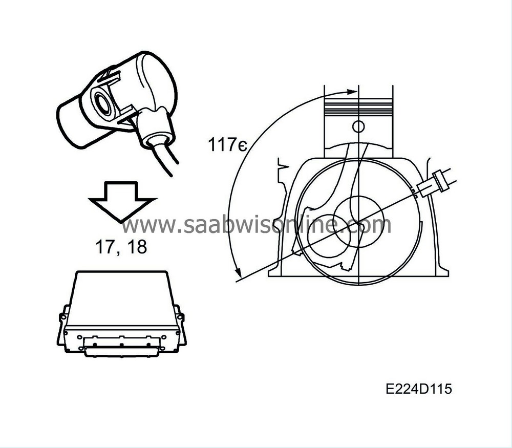
The crankshaft position sensor supplies pins 17 and 18 of the control module with information on crankshaft position and speed.
A slotted ring with 58 ribs is mounted on the crankshaft. Of inductive type, the sensor is mounted in the crankcase wall. The distance between the sensor and the slotted ring is between 0.4 and 1.3 mm and no adjustment is possible.
The sensor acts as a generator and produces a sinusoidal alternating current. By measuring the frequency, the control module can determine the engine speed. There are 2 ribs missing after the 58th one. When rib 1 then passes the sensor, the control module knows that the crankshaft is 117° before top dead centre (BTDC).
The current produced by the crankshaft sensor varies with engine speed. At idling speed it is 5-10 V (AC) and at 2500 rpm about 15-20 V (AC). However, it is the frequency and not the voltage which is of interest to the control module.
As soon as the control mo dule receives pulses from the crankshaft sensor, it grounds the fuel pump relay.
The resistance of the sensor is 860±90 ohms.
The engine speed is used for:
| • |
Indicating the engine operating point, in conjunction with the engine load. The operating point determines which values will be used in the matrices and tables.
|
|
| • |
Regulating idling speed.
|
|
The crankshaft angle is used for calculating when angle-related functions are to be activated, such as ignition, injection and knock detection.
| Diagnostics |
| • |
If the crankshaft position sensor is inoperative during starter motor cranking, diagnostic trouble code P0337 will be generated.
|
|
| • |
There is no substitute value for the crankshaft position sensor.
|
|


