Leak test, fuel pressure, flow capacity and adaptation procedure
|
|
Leak test, fuel pressure, flow capacity and adaptation procedure
|
The car can exhibit certain fault symptoms without generating a diagnostic trouble code. This can be due to an air leak in the system or insufficient fuel pressure and flow capacity.
The fault diagnosis listed below includes checking air leaks, fuel pressure, flow capacity and adaptation procedures. If a trouble code is present the appropriate fault diagnosis procedure should be used. The method below is to be used if the problem can not be traced with a diagnostic trouble code.
 Warning
|
|
Removal of the fuel pressure regulator involves partial dismantling of the car's fuel system. The following points must therefore be observed in connection with this work:
|
|
•
|
Have a class BE fire extinguisher on hand! Be aware of the risk of sparks, i.e. in connection with electric circuits, short-circuiting, etc.
|
|
•
|
Absolutely No Smoking!
|
|
•
|
Ensure good ventilation! If there is approved ventilation for evacuating fuel fumes then this must be used.
|
|
•
|
Wear protective gloves! Prolonged exposure of the hands to fuel can cause irritation to the skin.
|
|
•
|
Wear protective goggles.
|
|
|
|
|
|
|
1.
|
Make 2 copies of the checklist at the end of this document. Fill out one of the copies before initiating diagnostic procedures.
|
|
3.
|
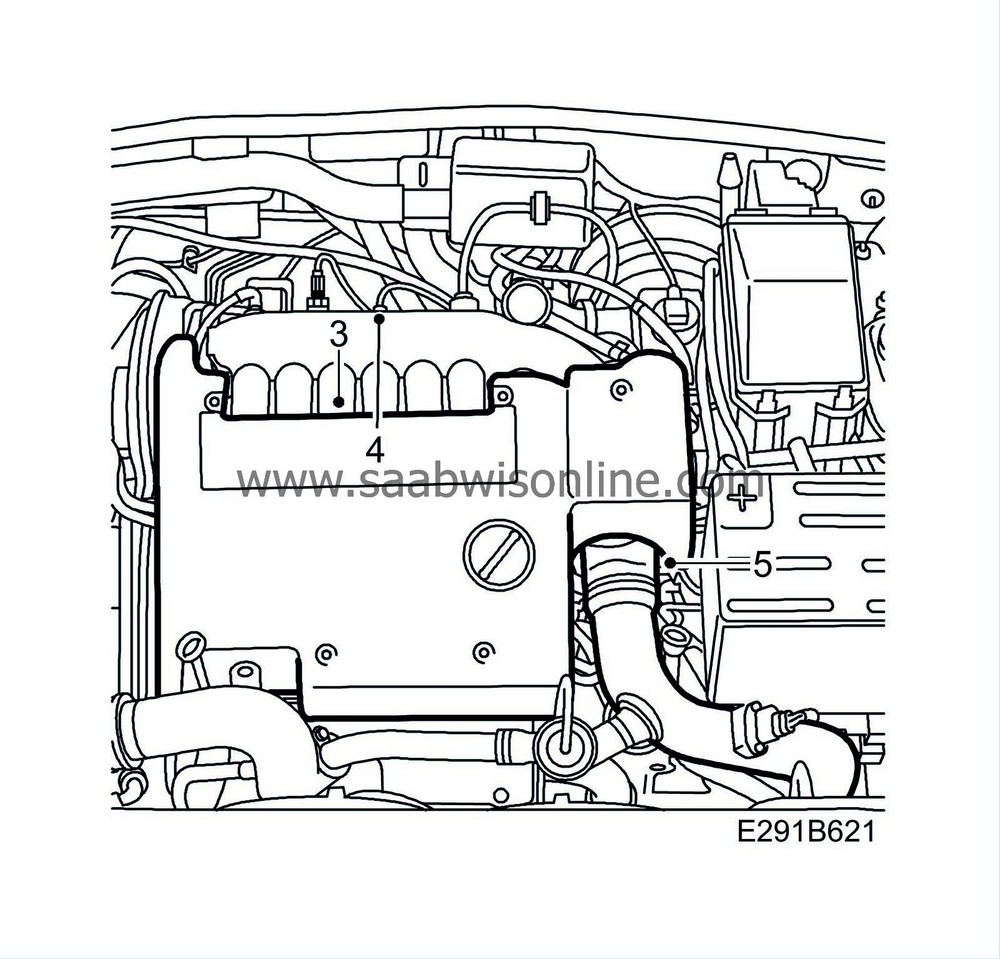
Remove the oil filler cap. Remove the upper engine cover. Refit the cap.

|
|
6.
|
Attach the charge air hose to the throttle body. On versions with a pipe, grease the O-ring with vaseline.
Pressure test the system as follows:
|
|
8.
|
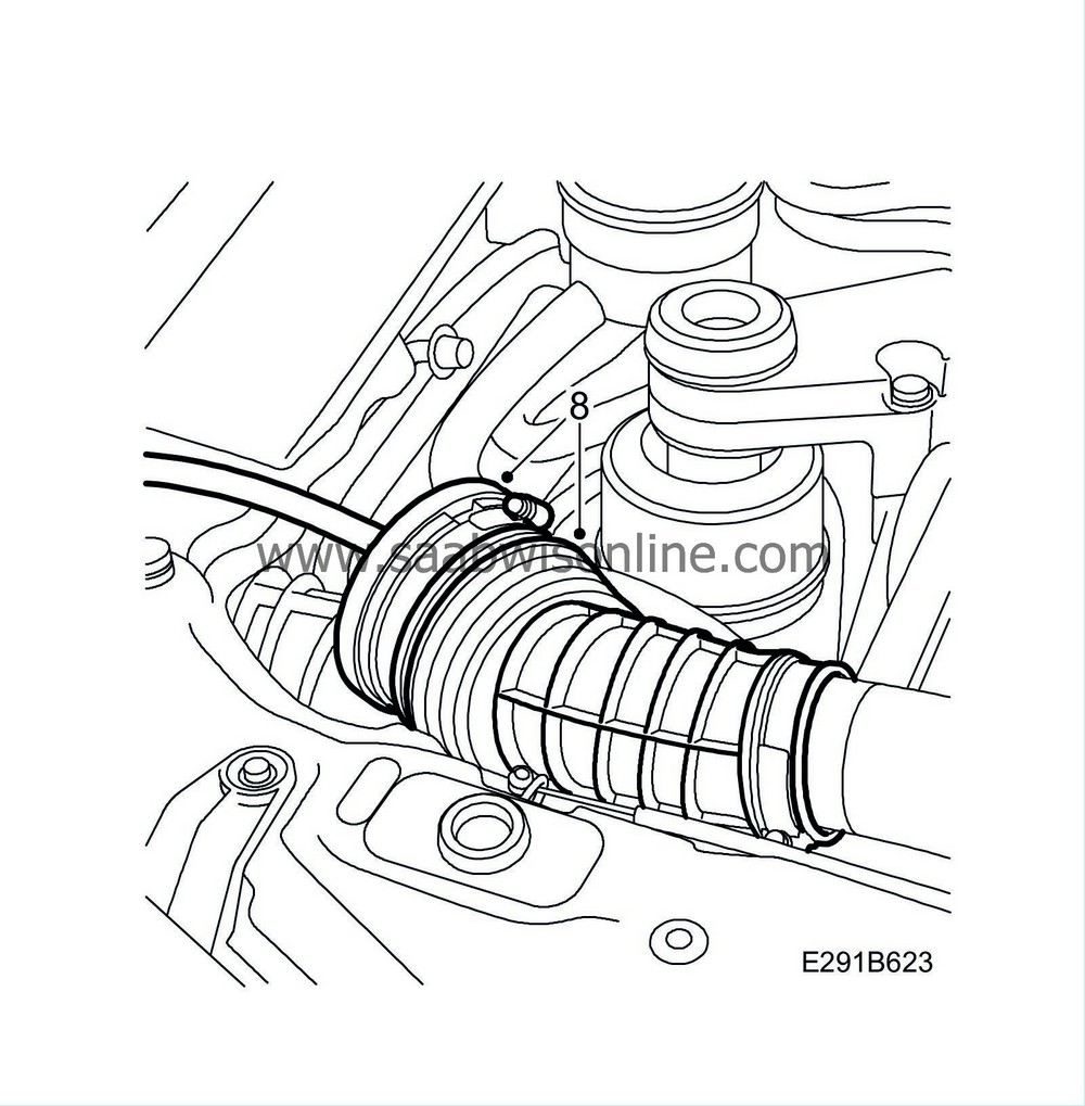
Detach the hose from the mass air flow sensors. Plug the hose with
83 95 659 Plug kit
and connect the accompanying pressure regulator to an external compressed air outlet.

|
Important
|
|
Close the pressure regulator before connecting it to the air pressure outlet.
|
|
|
|
|
9.
|
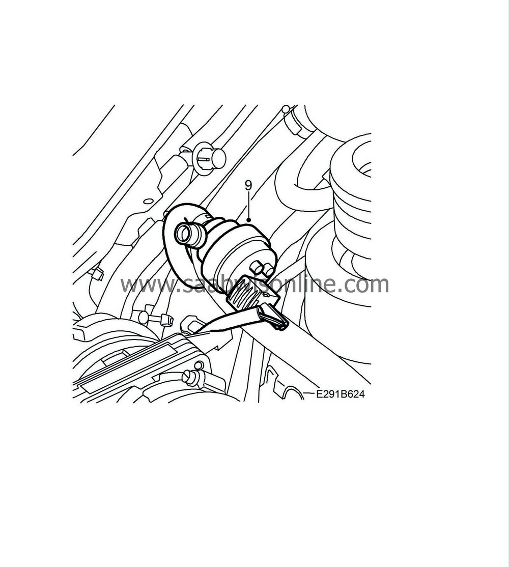
Detach the hose from the EVAP canister purge valve.

|
|
10.
|
Pressurize the intake system by carefully turning the pressure regulator until max. 0.6 bar of overpressure is reached. Read off the value on
83 93 514 Charge pressure gauge
.
|
|
11.
|
The entire intake system is now pressurized and leaks can be located using leak detection spray or soapy water. Check all components, hoses and connections, and rectify any leaks that can be heard.
|
Important
|
|
Only leaks that can be heard will affect the function of the engine management system. When leak-detecting spray or soapy water is used, even small leaks will be found. These do not need to be addressed.
|
|
|
|
|
12.
|
Remove the plugs and connect the hoses to the mass air flow sensor.
|
|
13.
|
Connect the hose to the EVAP canister purge valve.
|
|
14.
|
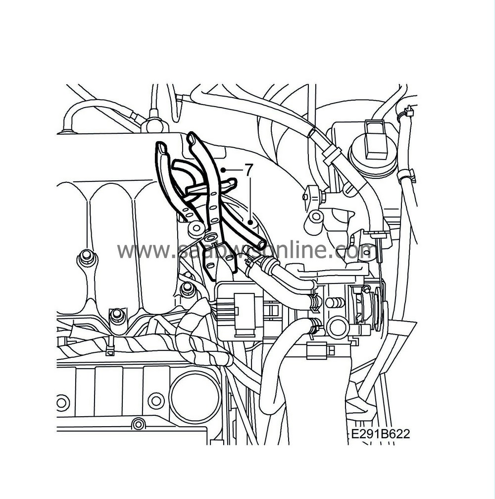
Remove the pinch-off pliers from the crankcase ventilation hose and check valve hose. Connect the hose to the check valve.
|
|
15.
|
Check the control module's software version in Tech 2. If there is a more recent version in WIS it should be programmed into the control module.
Checking fuel pressure / flow capacity
|
Important
|
|
Use the assistance of a colleague when measuring on the move.
|
|
|
|
|
17.
|
Measure fuel pressure while driving with as high a load as possible. Read the measurements on the pressure gauges. The pressure differential should always be 3 bar of fuel pressure according to the table below.
Drive thereafter with varying loads and engine speeds. Check that the fuel pressure follows the pressure in the intake manifold.
If the pressure differential is incorrect, check the fuel pressure regulator, fuel pump and fuel lines (delivery and return). Check that the EVAP purge valve works. Refer to
Checking for leaks in the evaporative emission control system
.
Pressure, intake manifold
|
Fuel pressure
|
-0.6 to -0.4 bar
|
2.4-2.6 bar
|
0 bar (atmospheric pressure)
|
3.0 bar
|
0.6 bar
|
3.6 bar
|
|
|
18.
|
Check the fuel adaptation with the help of Tech 2. Carry out the adaptation as follows:
|
|
|
18.a.
|
Turn off the A/C or ACC
|
|
|
18.b.
|
Engine temperature should be over 80°C and the engine should have been running for at least 3.5 minutes. The adaptation must be completed within 10 minutes of engine start-up.
|
|
|
18.c.
|
Drive on a flat road at between 1500 - 2750 rpm in 5th or 4th gear, ideally keeping the accelerator completely still for approximately 2 minutes.
|
|
|
18.d.
|
Stop the car and let the engine idle.
|
|
|
18.e.
|
Read "multiplicative adaptation" on Tech 2.
|
|
|
18.f.
|
Read "additive adaptation" on Tech 2. If the value does not change within 10 minutes, turn off the engine and start it up again and repeat steps 18b - 18f. If the value still does not change, go to step 23.
|
|
19.
|
Carry out the adaptation of the throttle opening.
|
|
|
19.a.
|
Coolant temperature should be over 80°C. Turn off the A/C or ACC.
|
|
|
19.b.
|
Let the engine idle for 2 minutes. Turn off the engine.
|
|
|
19.c.
|
Repeat step 19b 3 times.
|
|
20.
|
Fill out the second copy of the checklist.
|
|
21.
|
Disconnect the pressure measurement tools and Tech 2.
|
|
22.
|
Refit the upper engine cover and oil filler cap.
|
|
23.
|
If the problems have not been solved, contact the importer's technical support. Have the checklists that were filled out ready.
|
|
1.
|
Describe the fault symptom ..................................................................................................................
...................................................................................................................................................
....................................................................................................................................................
|
|
3.
|
Turn off A/C or ACC and let the engine idle. Coolant temperature should be over 80°C.
|
Note
|
|
Do not erase diagnostic trouble codes.
|
|
|
4.
|
Read and note any diagnostic trouble codes: ...........................................................................................................
|
|
5.
|
Choose "Engine" - "Trionic" - "Read value / Activate" in Tech 2. Read and note the following values:
|
|
|
Unit
|
Ignition On
|
Idle
|
Desired value
|
Engine RPM
|
rpm
|
-------------
|
|
800-850
|
Airmass / Combustion
|
mg/c
|
-------------
|
|
|
Coolant Temperature
|
°C
|
|
|
85-100
|
Variation from measured air mass
|
%
|
-------------
|
|
max. 10
|
Intake air temperature
|
°C
|
|
|
40-60
|
Atmosphere Absolute Pressure
|
kPa
|
|
|
90-115
|
Charge Air Absolute Pressure
|
kPa
|
|
|
95-110
|
Manifold Absolute Pressure
|
kPa
|
|
|
25-60
|
Additive adaptation
|
mg/c
|
|
|
max. 0.6
|
Multiplicative adaptation
|
%
|
|
|
max. 6
|
Charge Air Adaptation
|
%
|
|
|
max. 10
|
|
|
Number of knockings
|
Number of misfires
|
No. 1 cylinder
|
|
|
No. 2 cylinder
|
|
|
No. 3 cylinder
|
|
|
No. 4 cylinder
|
|
|
No. 5 cylinder
|
|
|
No. 6 cylinder
|
|
|
Under “system information” you will find information on chassis and version numbers for Trionic T7
Chassis number.
|
|
Software version
(obligatory)
|
|
A plate with the engine number is located on the engine block, as specified under
Engine serial No.
.
To see the colour of the injectors, remove the upper engine cover.
Engine serial No.
|
|
Fuel injector, colour
|
|


 Warning

