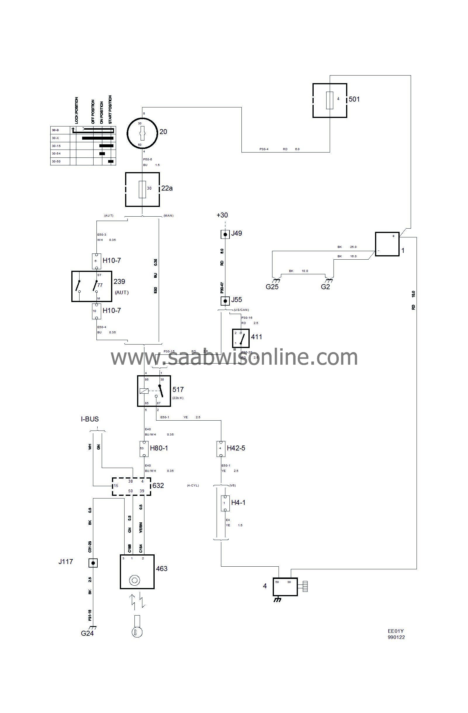
Starting system with immobilizer
|
|
Starting system with immobilizer
|

|
No.
|
Name
Location
|
Illus.
|
|
Components
|
|
1
|
Battery
in engine bay
|
|
4
|
Starter motor
on rear long side of engine (left)
|

|
20
|
Ignition switch
in floor console between front seats
|

|
22a
|
Fuse box, dashboard
on end of dashboard next to driver's door
|

|
77
|
Switch, immobilizer, automatic transmission (in 239)
in transmission range switch 2 on gearbox
|

|
239
|
Transmission range switch 2, automatic transmission (31,77)
on automatic gearbox in engine bay
|

|
411
|
Switch, clutch, immobilizer
on bulkhead partition by clutch pedal
|

|
463
|
Antenna unit, immobilizer
by ignition switch
|

|
501
|
Main fuse box, maxi fuses
behind the battery
|

|
517
|
Relay, starter relay
on relay box in dashboard
|

|
632
|
Control module, TWICE
under LH seat
|

|
|
|
4-pin connector
|
|
H4-1
|
At generator
|

|
|
|
10-pin connector
|
|
H10-7
|
Under the battery tray
|

|
|
|
42-pin connector
|
|
H42-5
|
In the centre of the bulkhead partition (engine bay side)
|

|
|
|
80-pin connector
|
|
H80-1
|
In the connector bracket under the LH A-pillar.
|

|
|
|
Crimp connectors
|
|
J49
|
LHD:
Approx. 180 mm from the maxi-fuse box
RHD:
Approx. 220 mm from the maxi-fuse box
|

|
J55
|
LHD:
Approx. 125 mm from branching of DICE control module towards relay box
RHD:
Approx. 90 mm from branching point of DICE control module towards main fuse box
|

|
J117
|
Approx. 230 mm from branching of switch panel towards RH seat
|

|
|
|
Grounding points
|
|
G2
|
On LH of the structural member behind the headlamp
|

|
G24
|
Behind the seat member under the RH seat
|

|
G25
|
On the gearbox
|

|