Anti-theft alarm fitting kit
|
|
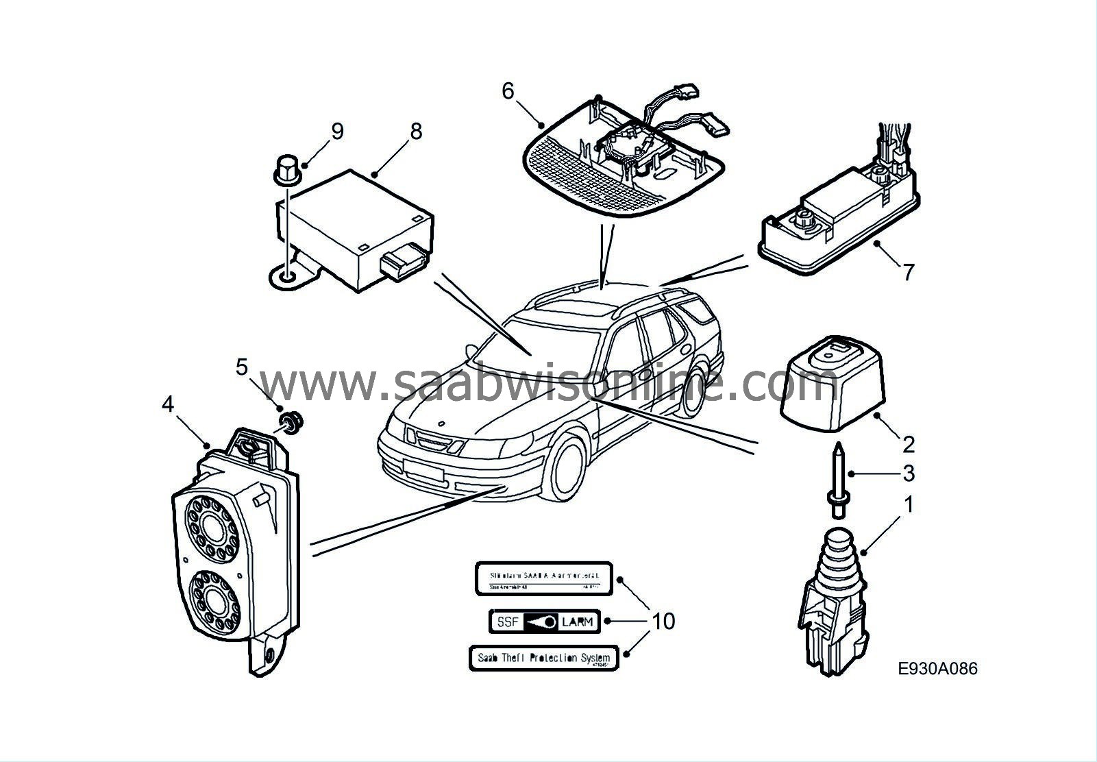
Anti-theft alarm fitting kit
|
|
2.
|
Protective cover for bonnet switch
|
|
6.
|
Lens cover with glass breakage sensor (textile or leather trim)
|
Labels, decals
The labels and decals should be attached to the front side windows and the windscreen as described in the Service Manual “Group 1 Service” when the anti-theft alarm is installed and working.
|
2.
|
Protective cover for bonnet switch
|
|
6.
|
Front lens cover with glass breakage sensor (textile or leather trim)
|
|
7.
|
Rear lens cover with glass breakage sensor
|
Labels, decals
The labels and decals should be attached to the front side windows and the windscreen as described in the Service Manual “Group 1 Service” when the anti-theft alarm is installed and working.
|
1.
|
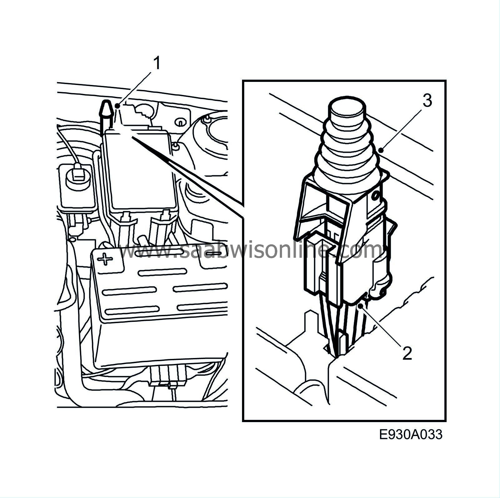
Open the bonnet and lift the main fuse box to find the wiring harness with connector for the bonnet switch. Spray with connector with Contact 61.
|
|
2.
|
Plus the connector on to the switch.
|
|
3.
|
Fit the switch in its holder.
|
|
Protective cover for bonnet switch (EU, GB)
|

|
1.
|
Open the bonnet. On the inside of the bonnet there is a predrilled hole exactly above the bonnet switch.
|
|
2.
|
Fit the cover into the hole using a rivet.
|
|
1.
|
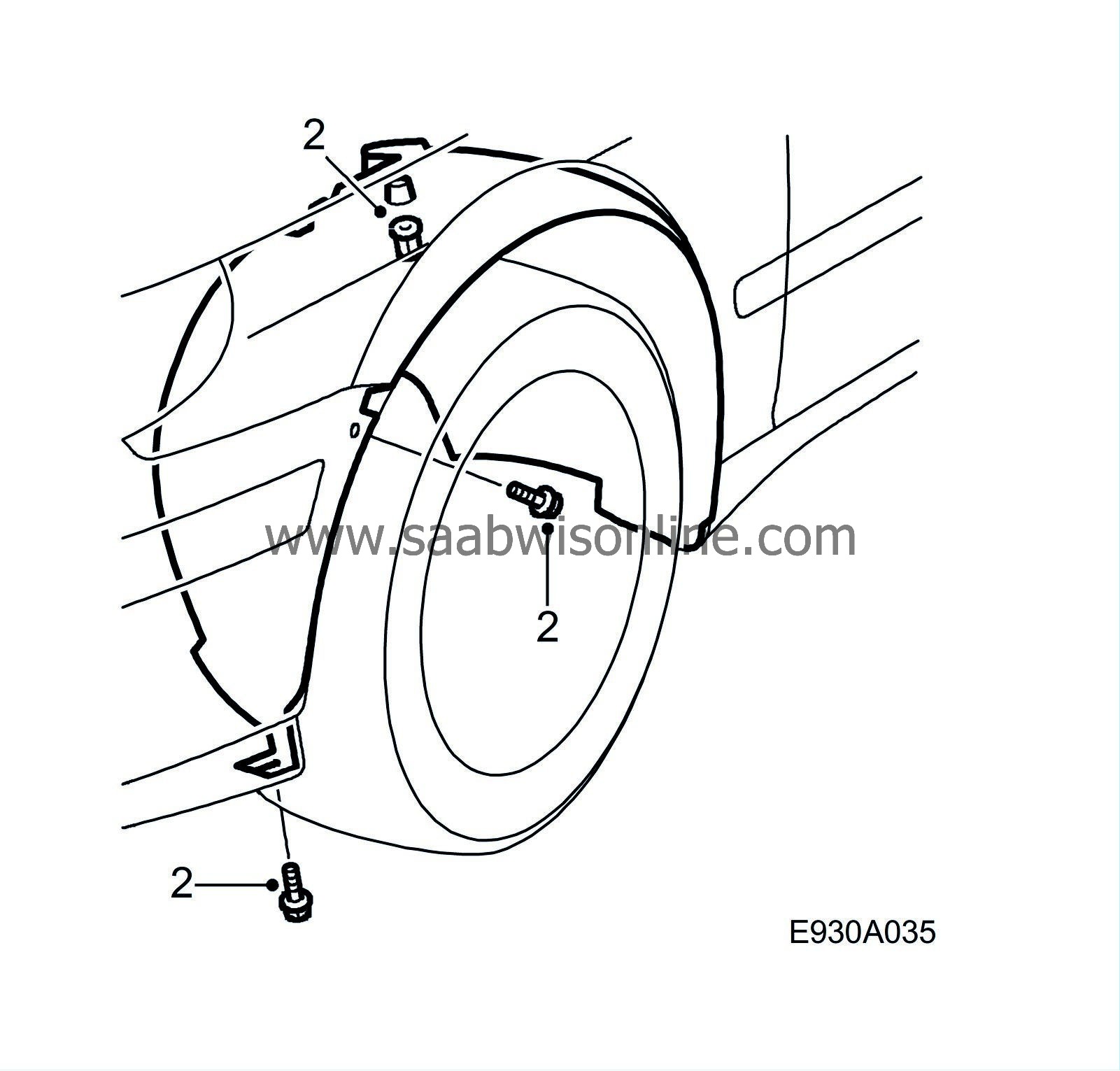
Raise the car and remove the left front wheel.
|
|
2.
|
Remove the front portion of the wing liner in the LH front wheel housing. Find the wiring harness with a 3-pin connector. Spray the switch with Contact 61.
|
|
3.
|
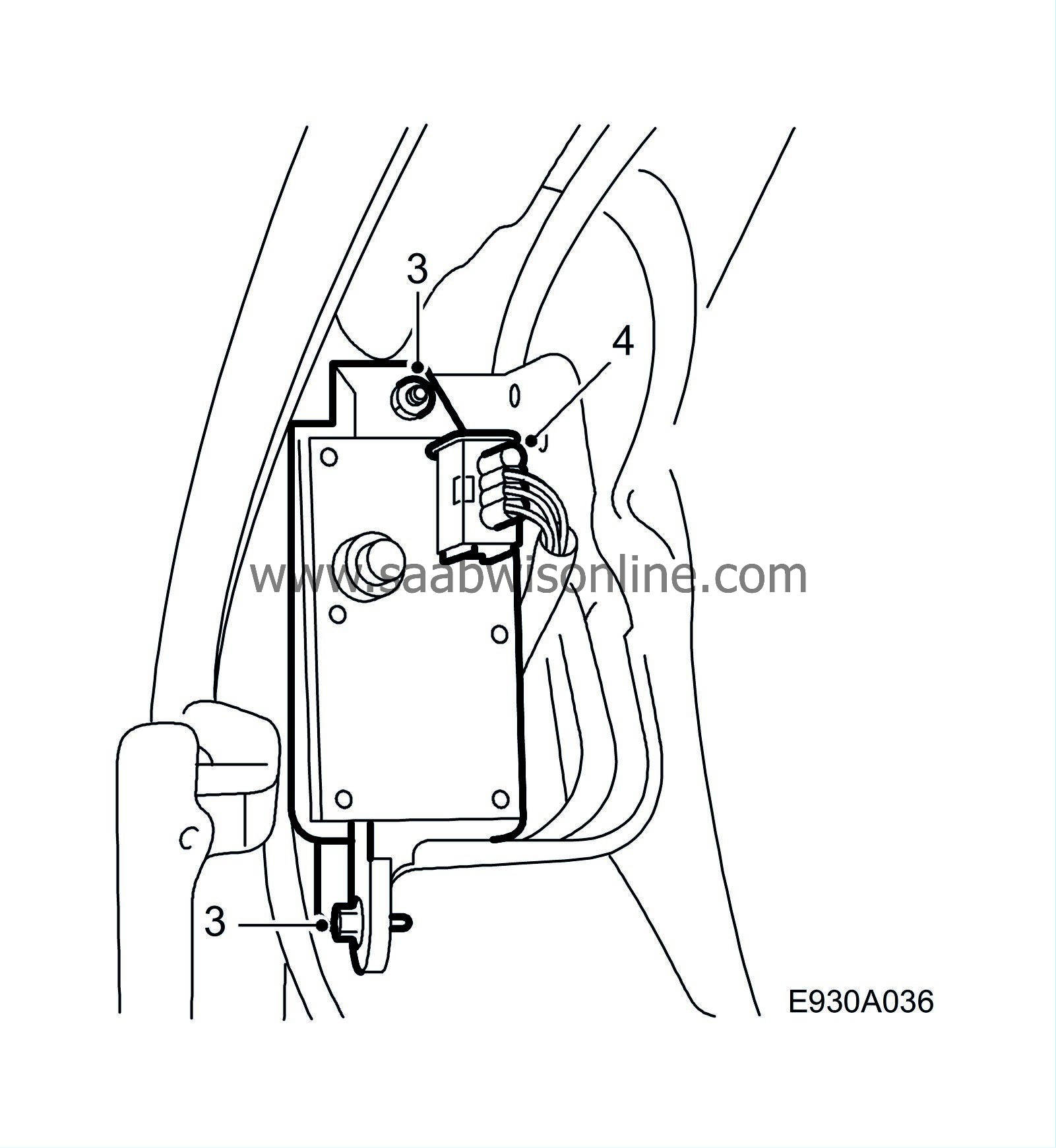
Fit the siren on to the prewelded screw and tighten it down with a nut and a screw.
|
|
4.
|
Plug in the connector on the siren.
|
|
5.
|
Fit the wing liner and left-hand front wheel in position again and lower the car to the ground.
|
|
Glass breakage sensor (4D)
|

|
1.
|
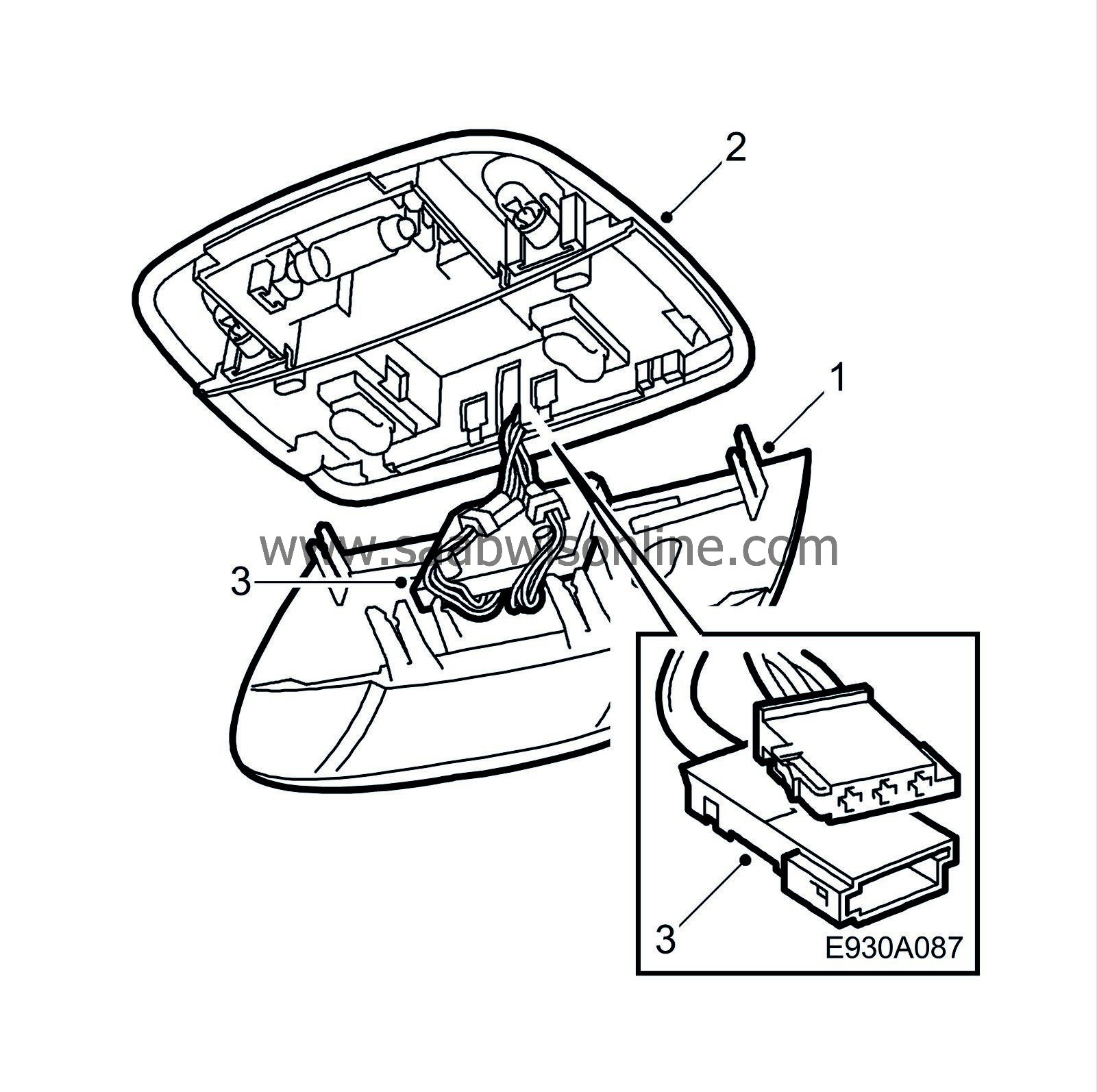
Remove the existing lens cover from the centre ceiling lamp by pulling it downward.
|
|
2.
|
Remove the switch panel from the ceiling lamp to access the connector for the glass breakage sensor. Use a small screwdriver to release the belt tongues on the LH and RH side when the panel is removed. Pull out the switch and refit the switch panel.
|
|
3.
|
Connect the glass breakage sensor on the new lens cover to the connector.
|
|
4.
|
Press the lens cover into position.
|
|
5.
|
Finally, the glass breakage sensor must be programmed for theft protection with the diagnostic tool. If an angle sensor is also to be fitted, perform programming after the angle sensor has been fitted. See
Programming, Theft protection
|
|
Glass breakage sensor, front (5D)
|
|
1.
|
Remove the existing lens cover from the centre ceiling lamp by pulling it downward.
|
|
2.
|
Remove the switch panel from the ceiling lamp to access the connector for the glass breakage sensor. Use a small screwdriver to release the belt tongues on the LH and RH side when the panel is removed. Pull out the switches and refit the switch panel.
|
|
3.
|
Connect the glass breakage sensor on the new lens cover to the connectors.
|
|
4.
|
Press the lens cover into position.
|
|
5.
|
Finally, the glass breakage sensor must be programmed for theft protection with the diagnostic tool. If an angle sensor is also to be fitted, perform programming after the angle sensor has been fitted. See
Programming, Theft protection
|
|
Glass breakage sensor, rear (5D)
|
|
1.
|
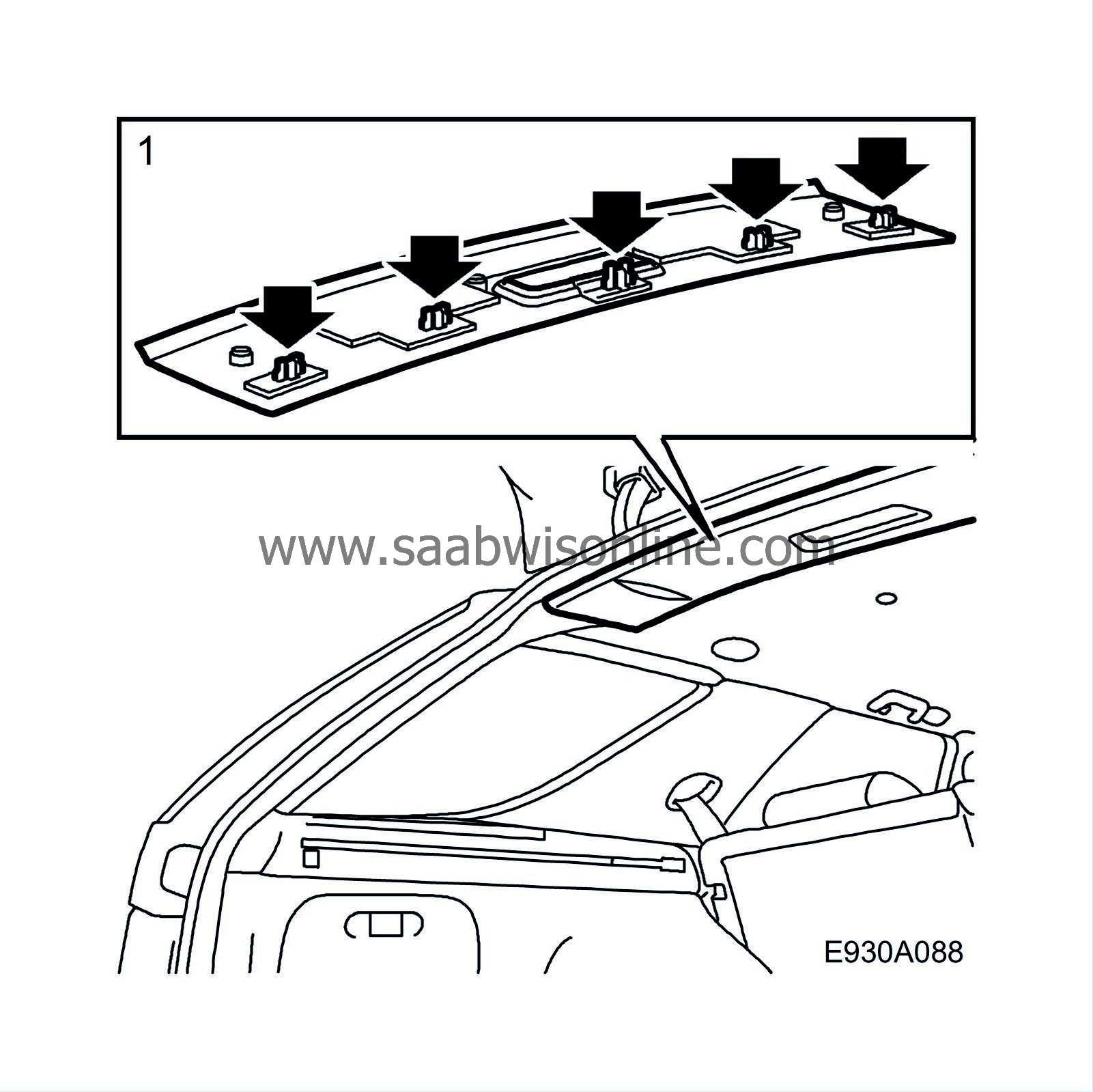
Remove the ceiling lamp in the luggage compartment.
|
|
2.
|
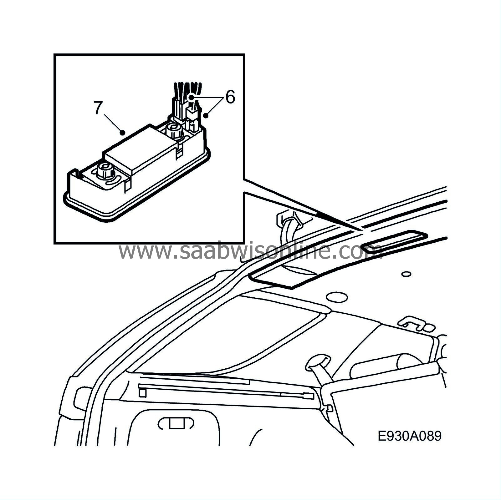
Remove the glass from the lamp.
|
|
3.
|
Remove the plastic body from the cable entry.
|
|
4.
|
Pull out the cable and connector for the glass breakage sensor.
|
|
5.
|
Fit the plastic body in the cable entry.
|
|
6.
|
Connect the glass breakage sensor and the lamp and fit the cover.
|
|
7.
|
Fit the glass breakage sensor into the cover.
|
|
8.
|
Finally, the glass breakage sensor must be programmed for theft protection with the diagnostic tool. If an angle sensor is also to be fitted, perform programming after the angle sensor has been fitted. See
Programming, Theft protection
|
|
1.
|
Push the right-hand front seat forwards and adjust the back of the seat to a vertical position.
|
|
2.
|
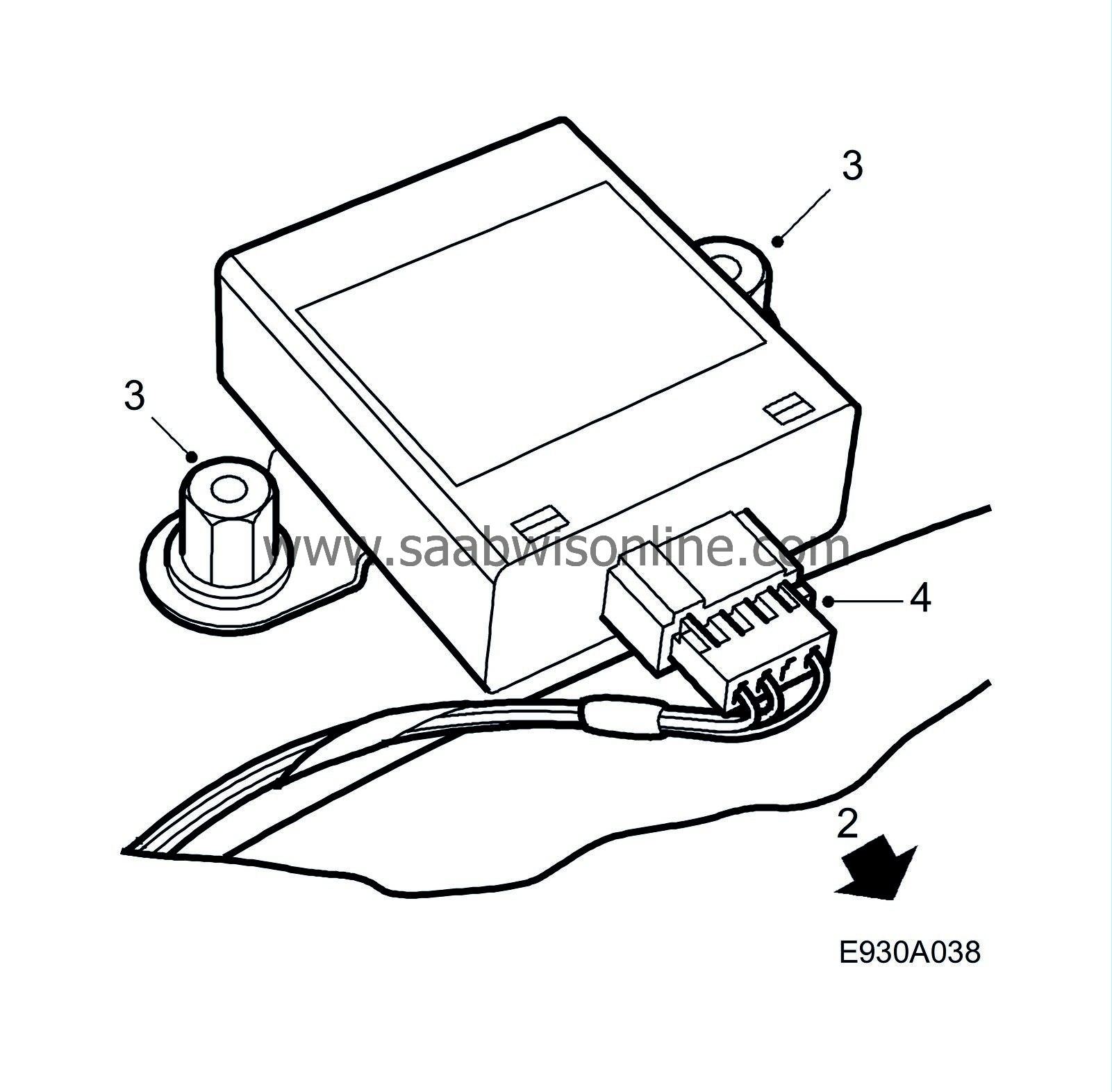
Fold the floor mat under the seat to reveal the attachment points (2 prewelded screws) and electrical connector for the tilt sensor.
|
|
3.
|
Fit the tilt sensor on the screws and tighten the plastic nuts.
|
|
4.
|
Plug the connector on to the sensor. Fold the mat back again and reposition the seat.
|


