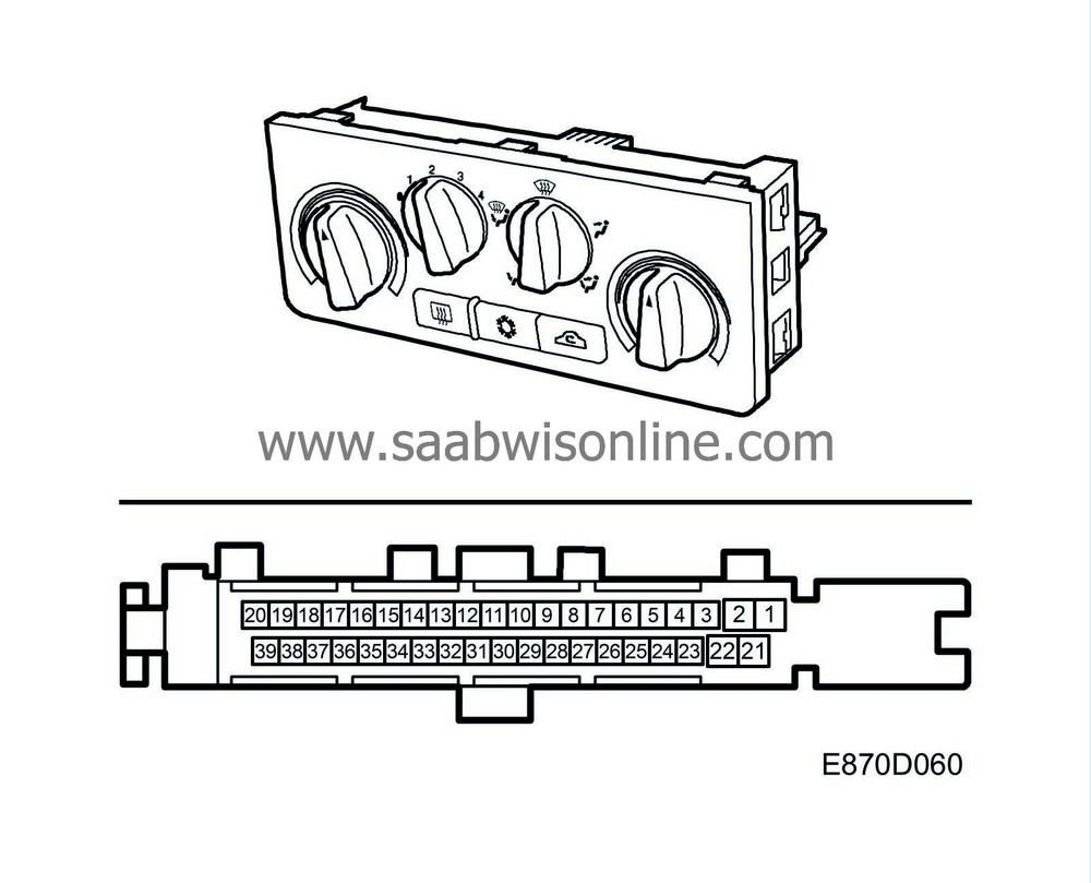
Control module
| Control module |
The control module is integrated in the MCC unit and is activated by +15 or by the parking heater input. If the control module is activated, the fan speed can be regulated. The function of the parking heater is described in a later section, see
 .
.
If the power supply falls below 9.5 V, all the stepping motors will cease to function until the voltage rises above 10 V.
Diagnostics
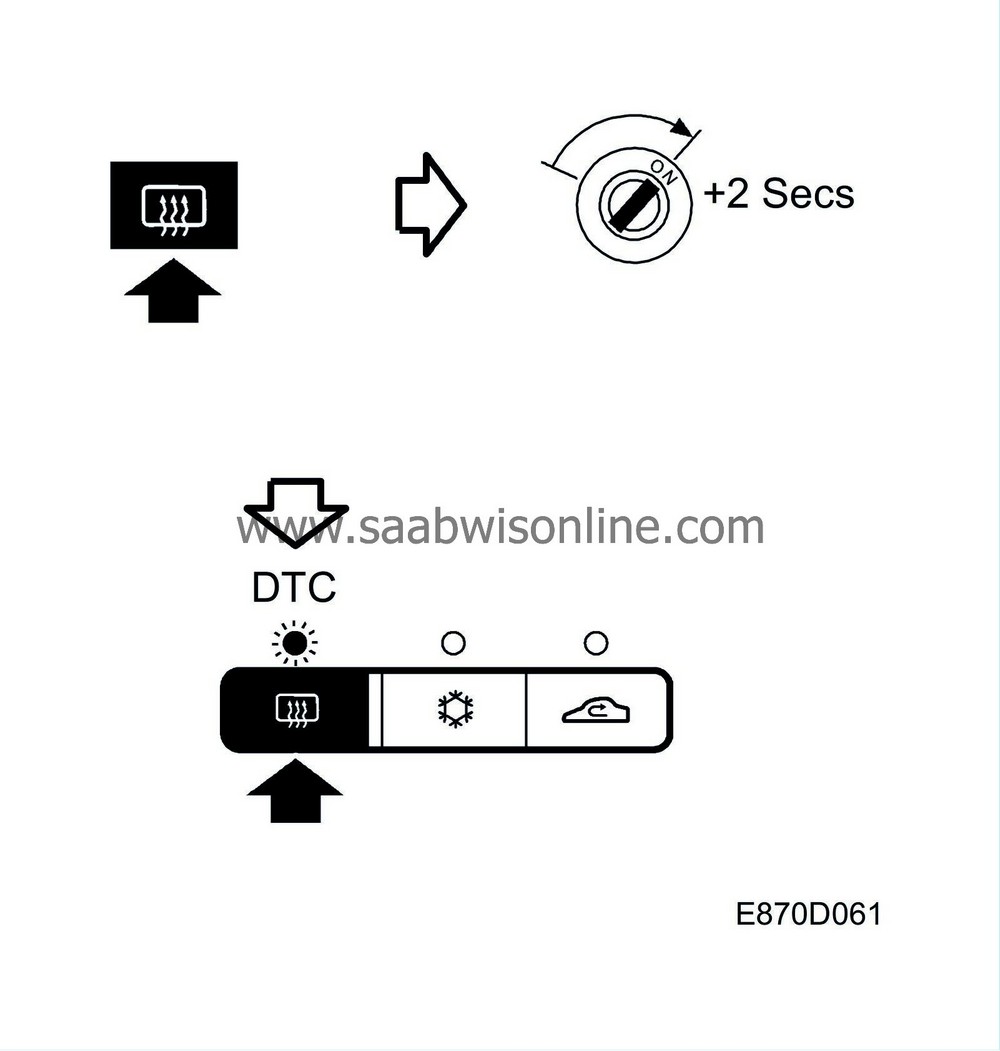
The control module is not connected to a bus and does not communicate with the diagnostics tool. A stored diagnostic trouble code flashes 6 times by the LED for the electrically heated rear window, if the button is depressed when the ignition is turned on and then for another 2 seconds.Only one fault can be stored at any one time. Diagnostic trouble codes are deleted by calibration after correcting the malfunction.
There is no diagnostic trouble code for internal faults in the control module.
| Control module power supply |
+30
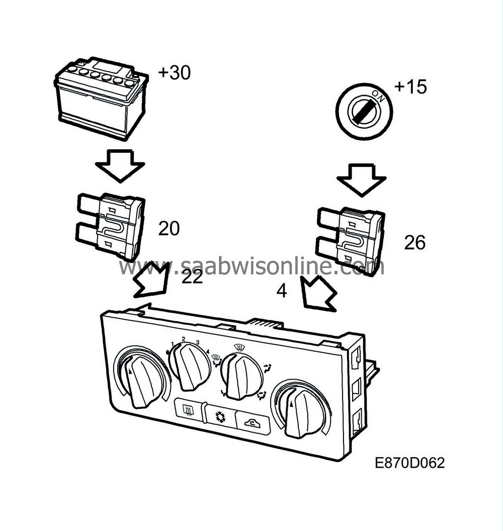
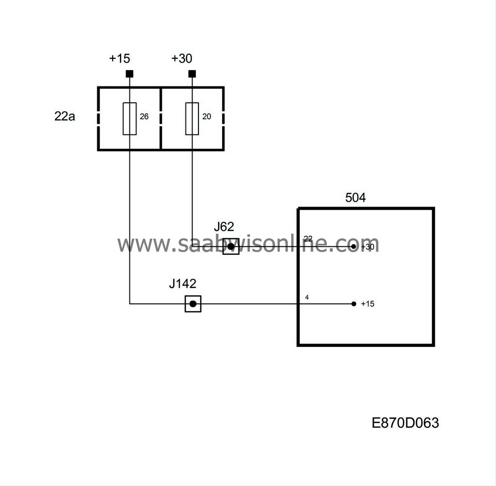
The MCC unit is supplied with current +30 via fuse 20 to pin 22.
+15
The MCC unit is current supplied with +15 via fuse 26 to pin 4. +15 is used to trip the control module.
Diagnostics
The fan speed cannot be regulated if there is no power supply.| Ground |
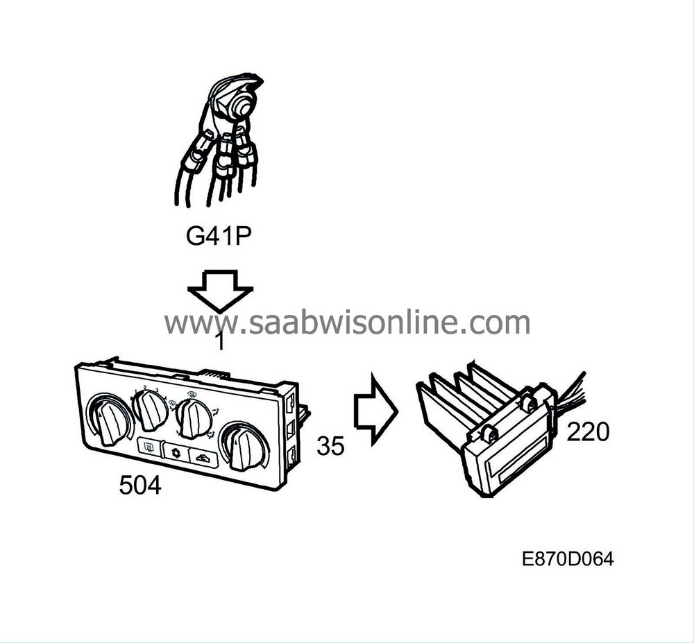
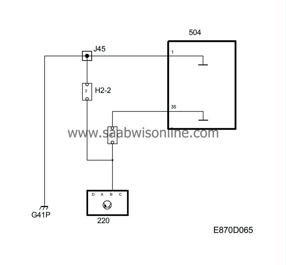
The MCC unit's power ground runs between G41P and pin 1. The fan control unit receives a reference ground from pin 35.

