Balancer shafts
| Balancer shafts |
| Engine vibration |
Continuous efforts are made towards improving car comfort for both the driver and passengers. Two areas of concern are engine vibration and noise level, both of which are a result of the basic engine design. Forces caused by combustion convert chemical energy into mechanical energy which act on the piston crowns. The reciprocating motion of the pistons and connecting rods together with the rotation of the crankshaft create inertial forces which cause the engine block to vibrate in various ways. At low engine speeds, the gas forces are greater than the inertial forces while the opposite is true for higher rpm. The most significant forces are produced periodically, once or twice per crankshaft rotation. These forces are designated as first and second-order inertia forces. First-order inertia forces are completely outweighed by the balanced crankshaft and the two pairs of pistons (1-4 and 2-3) turning in different directions simultaneously.
| Second-order forces acting vertically |

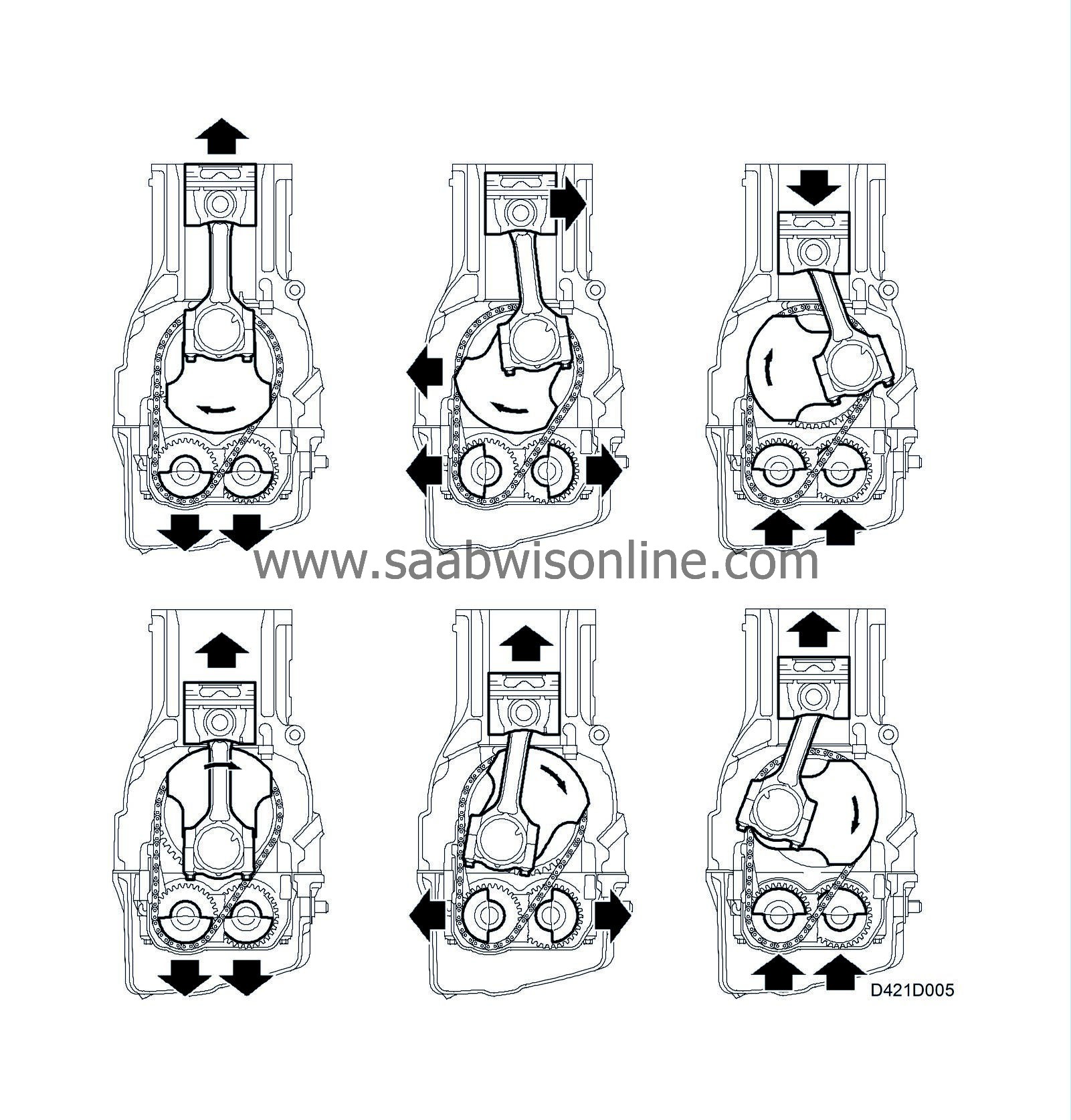
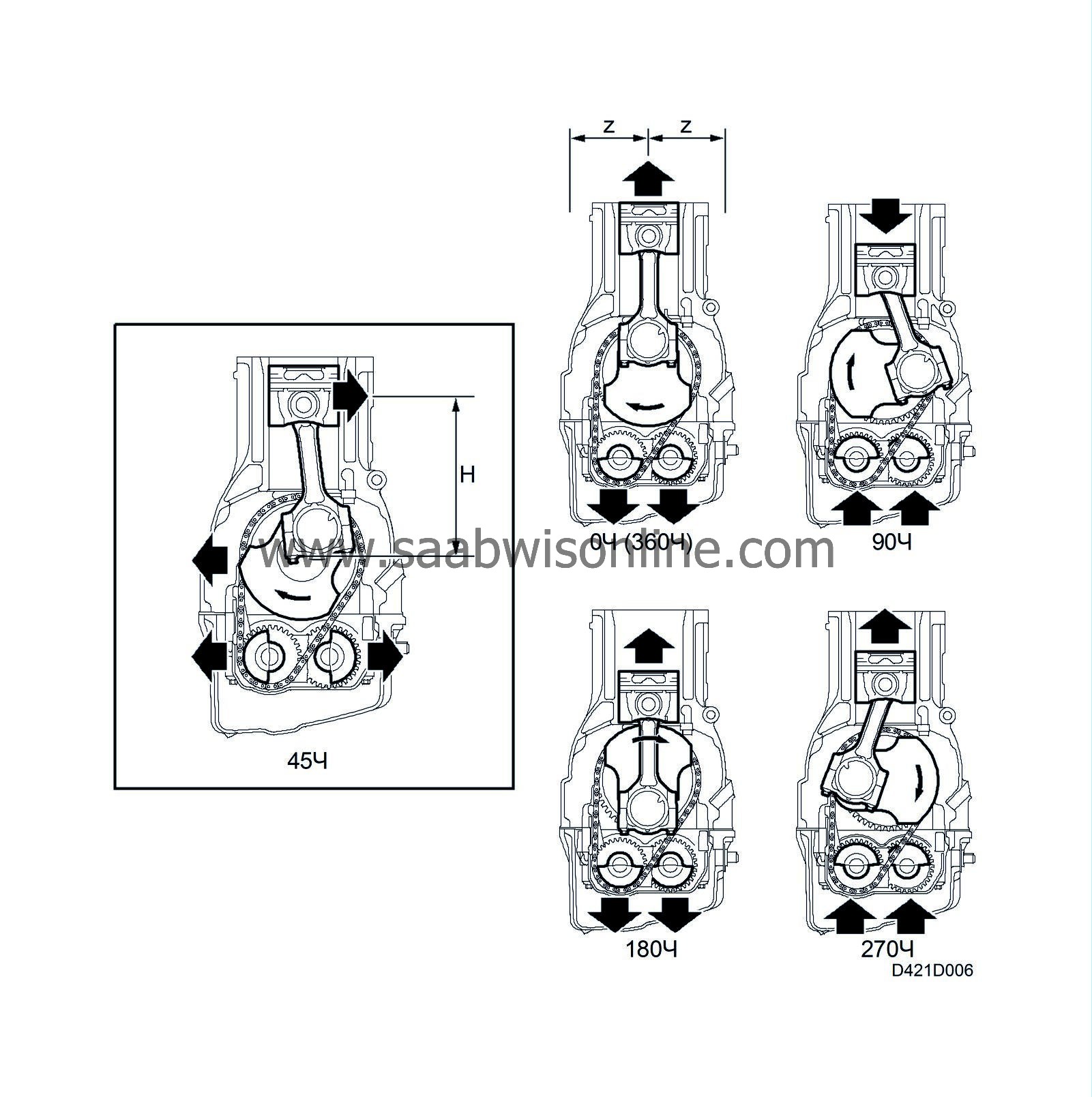
Inertia forces are caused by the fact that both descending pistons in a 4-cylinder engine at a specific crankshaft angle move a longer distance than the ascending pistons (lateral connecting rod movement accelerates the downward movement and retards the upward piston movement). The common centre of gravity of the vertical masses is therefore varied, which results in varied periodical ascending and descending forces occurring twice per crankshaft rotation that cause vertical vibration in the engine.
| Second-order forces acting laterally |
During the power stroke, the piston is pressed against the cylinder wall due to the angle of the connecting rod in relation to the cylinder bore. At higher engine speeds, the inertial forces are considerably greater. Regardless of engine speed, the lateral combustion and inertia forces vary twice per crankshaft rotation and cause lateral vibration in the engine.
| Balancer shaft system |

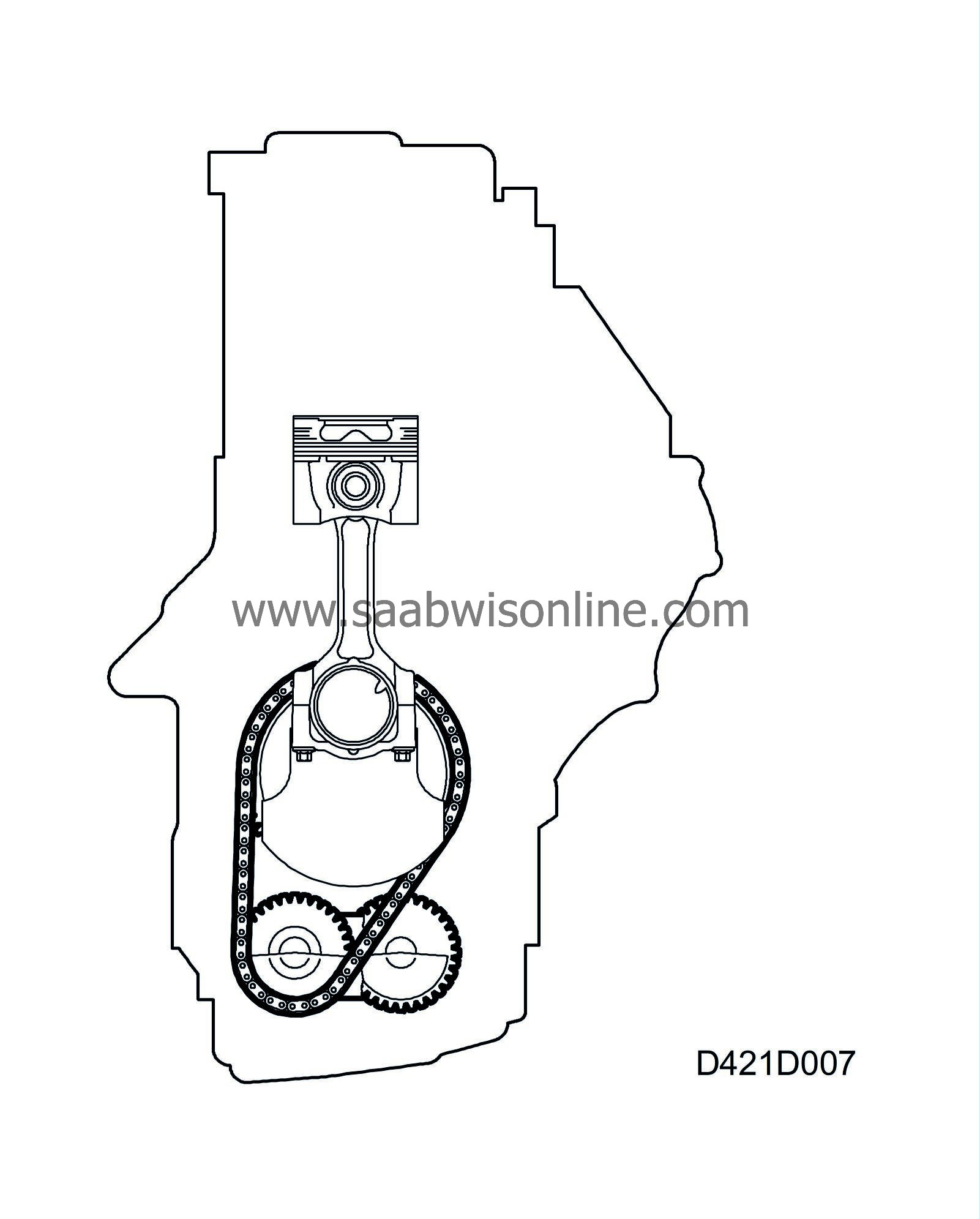
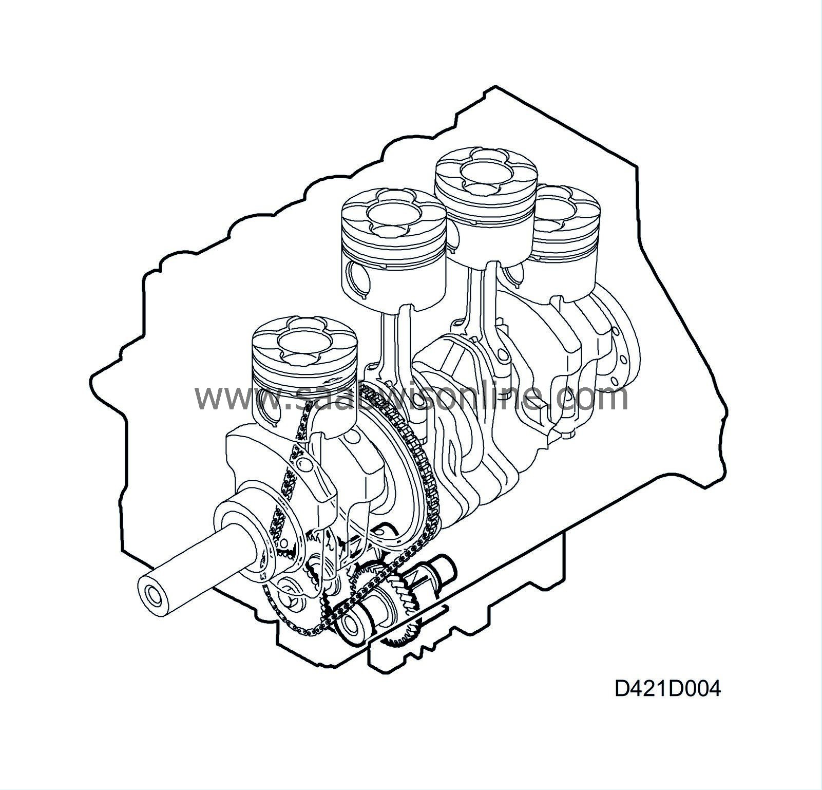
Saab has utilized the principle of balancer shaft in order to balance second-order inertial forces. Two balancer shafts, placed symmetrically on each side below the crankshaft in the crankcase are equipped with offset weights. One shaft is rotated by a chain on a crankshaft sprocket and the other shaft is rotated by a spur gear which is meshed with the chain-driven shaft. They rotate in opposite directions at twice the speed of the crankshaft.
Shaft weight placement reduces the mass forces caused by piston and connecting rod movement as well as the forces created during the power stroke.
The balancer shafts are mounted in a cast frame which also reinforces the crankcase and main bearings.
A necessary condition for correct balancer shaft function is that they have been precisely fitted. This implies that the crankshaft must be fixed in a position which corresponds to the top dead centre position for cylinder 1 when working on balancer shafts. Make sure the balance shafts are secured with the proper tools.
| Balancer shaft drive |

The balancer shafts are driven by the crankshaft via a chain for one of the shafts and a gear for the other. This results in a balancer shaft speed which is double the speed of the crankshaft with the shafts rotating in opposite directions.
The chain is partly guided with a fixed guide and partly by a moving chain guide with tensioner.
The chain tensioner employs spring tension but its movement is dampened by the effect of oil pressure in the opposite direction. This reduces chain wear as well as noise level.


