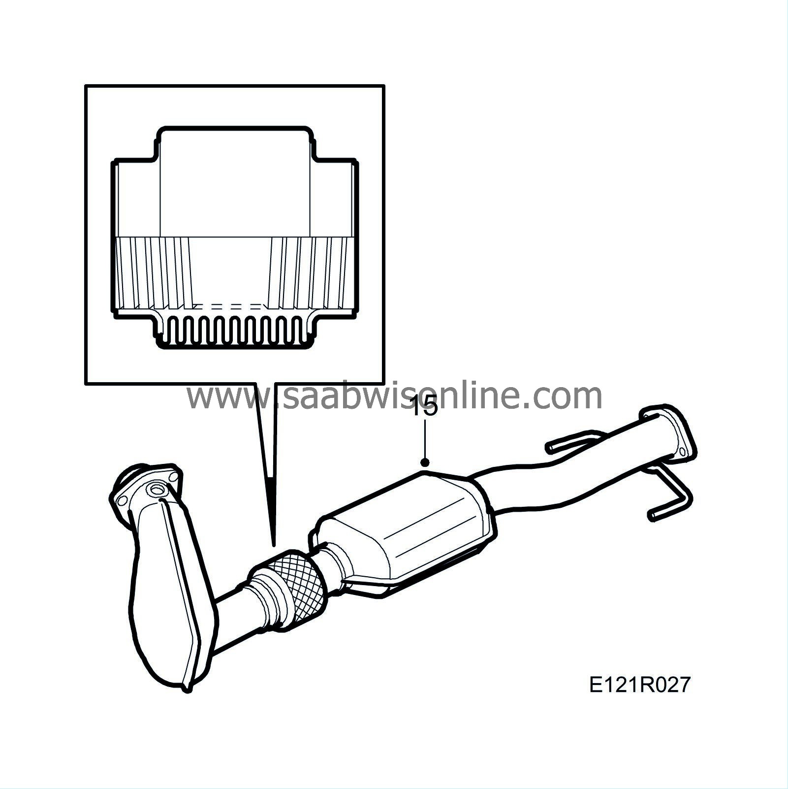
(210-2321) Adjustment of casting, rear engine mounting
| MODIFICATION INSTRUCTION | |
| Bulletin Nbr: | 210-2321 |
| Date: ........... | December 2001 |
| Market: | SE, DK, GB, IE, ZA |
| Adjustment of casting, rear engine mounting |
| Service Campaign 157 08 |
Cars in stock must be rectified before delivery.
Cars already delivered must be rectified in connection with a scheduled visit to the garage for service or repairs.
| Cars affected |
Saab 9-5 MY02 RHD with 4-cylinder petrol engine and manual gearbox within VIN range 23000428 - 23011818.
| Background |
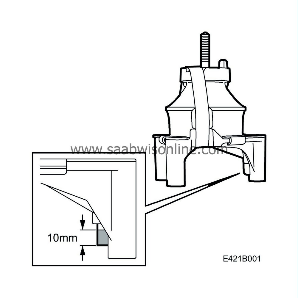
The rear engine mounting casting has a lug that touches the pipe to the steering gear. This can cause unwanted noise and corrosion.
| Parts required |
(16) 30 15 906 Zinc spray. Sufficient for approx. 50 cars.
| Procedure |
Check box C2 on the modification identity plate before taking any action. Continue as follows if the box is not marked.
| 1. |
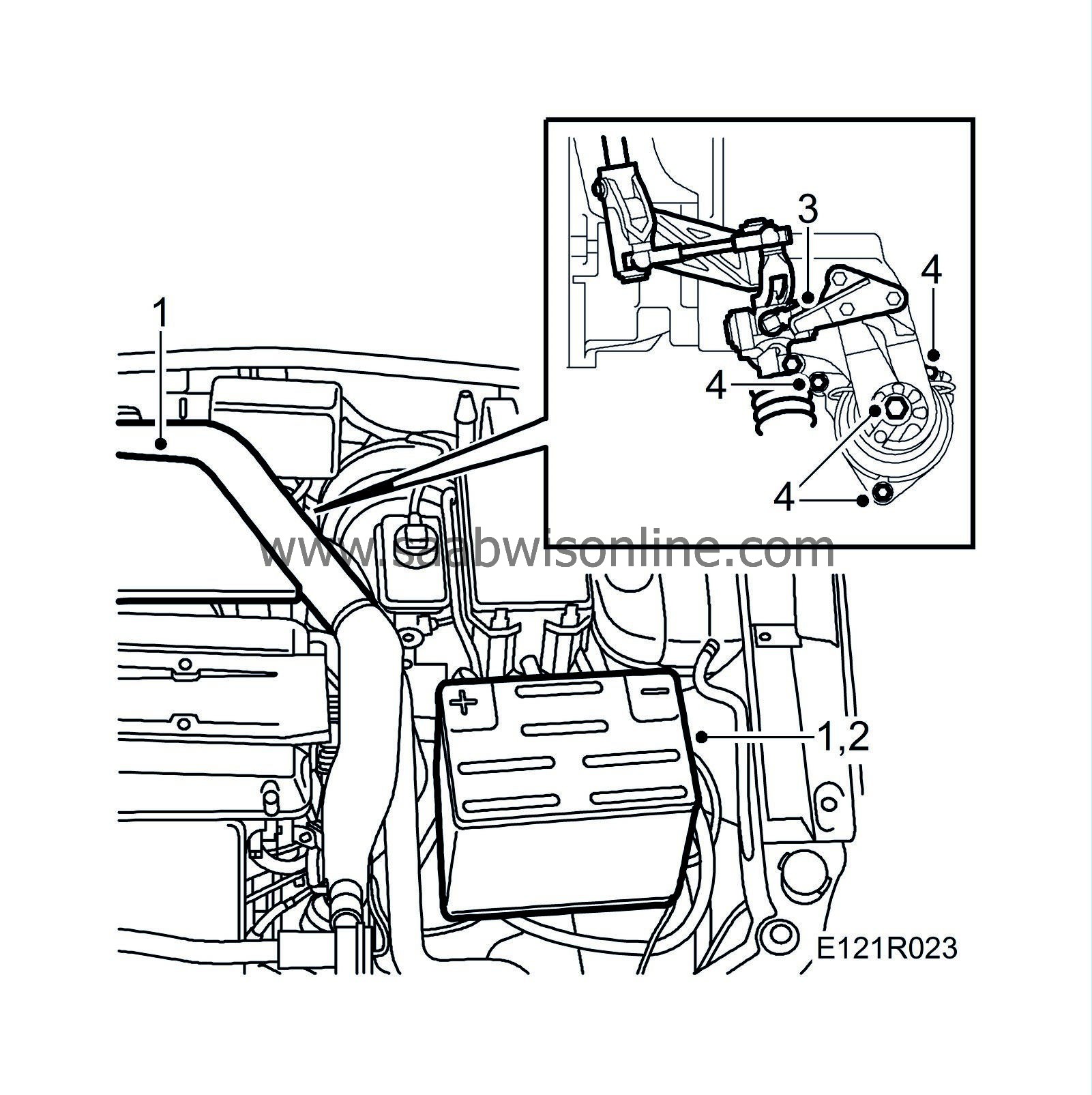
Cover the wings and remove the upper engine cover and battery cover. Make a note of the radio code, if necessary.
|
|
| 2. |
Disconnect the negative battery lead.
|
|
| 3. |
(Man.) Remove the stay supporting the gear linkage from the rear engine mounting bracket.
|
|
| 4. |
Remove the engine mounting's upper retaining nut and the bolts securing it to the subframe.
|
|
| 5. |
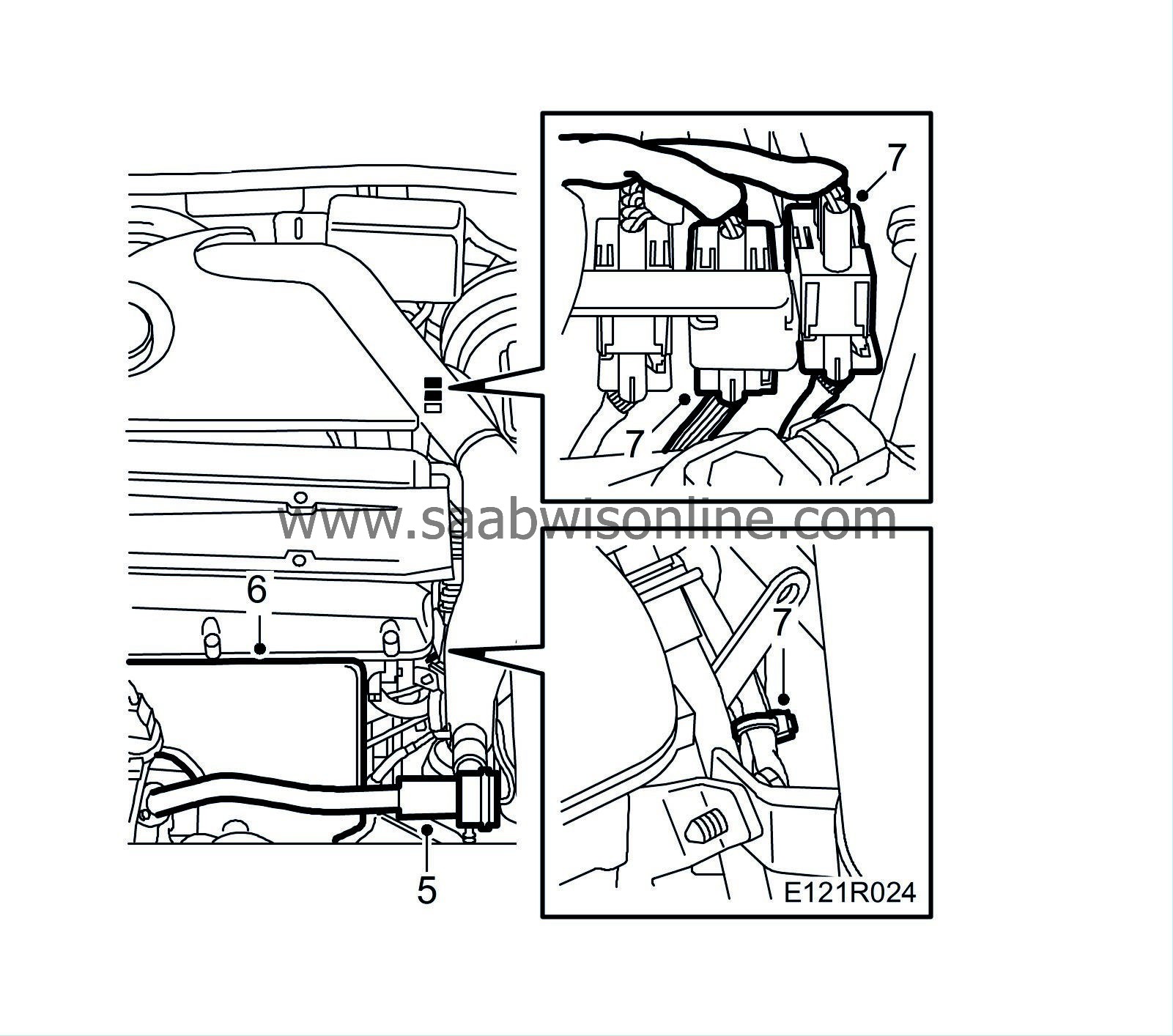
Remove the bypass pipe and valve.
|
|||||||
| 6. |
Remove the exhaust manifold heat shield.
|
|
| 7. |
Unplug the oxygen sensor connectors. Cut the cable tie and pull out the cables.
|
|
| 8. |
Fit
83 94 850 Lifting beam
.

|
|
| 9. |
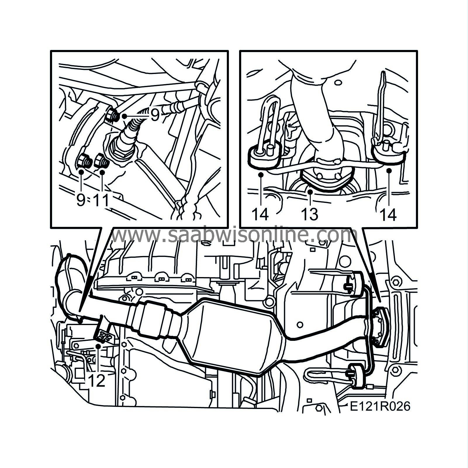
Undo the two upper nuts securing the joint between the turbocharger and front exhaust system.
|
|
| 10. |
Raise the car.
|
|
| 11. |
Undo the third nut holding the turbocharger and front exhaust system together.
|
|
| 12. |
Undo the upper bolt on the stay securing the catalytic converter to the engine.
|
|
| 13. |
Undo the pipe joint between the front and rear exhaust systems.
|
|
| 14. |
Remove the clips and carefully pull off the rubber mountings.
|
|
| 16. |
Remove the engine mounting bracket from the gearbox.

|
|
| 17. |
Remove the engine mounting.
|
|
| 18. |
Grind or saw off the section of the lug on the engine mounting that is shown in the illustration.
|
|
| 19. |
Apply (16) 30 15 906 Zinc spray to the section of pipe to the steering gear that is chaffed.
|
|
To fit
| 1. |
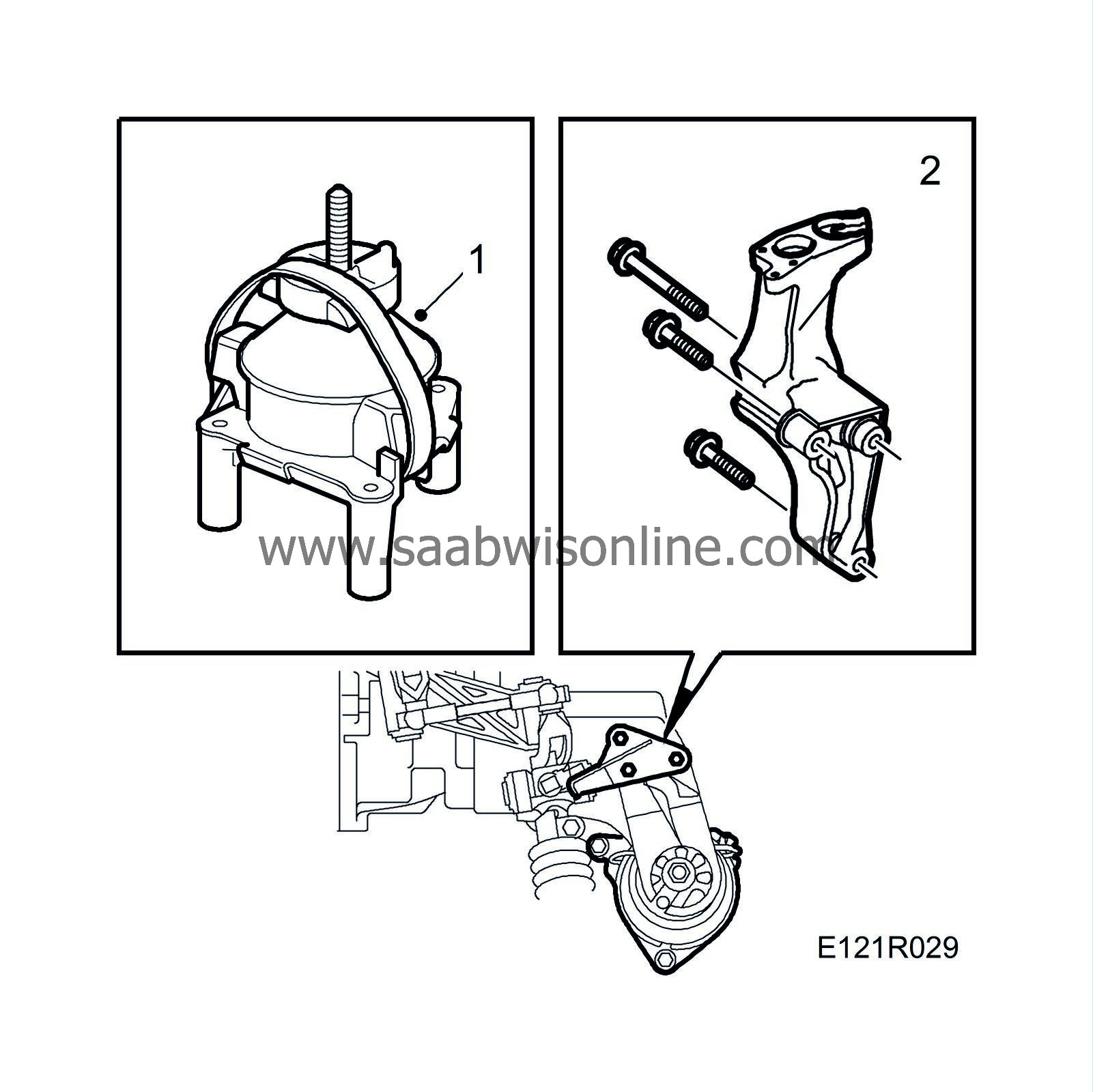
Position the engine mounting and thread the retaining bolts for the engine mounting bracket.
|
|
| 2. |
Fit the engine mounting bracket to the gearbox.
Tightening torque 84 Nm (62 lbf ft) |
|
| 3. |
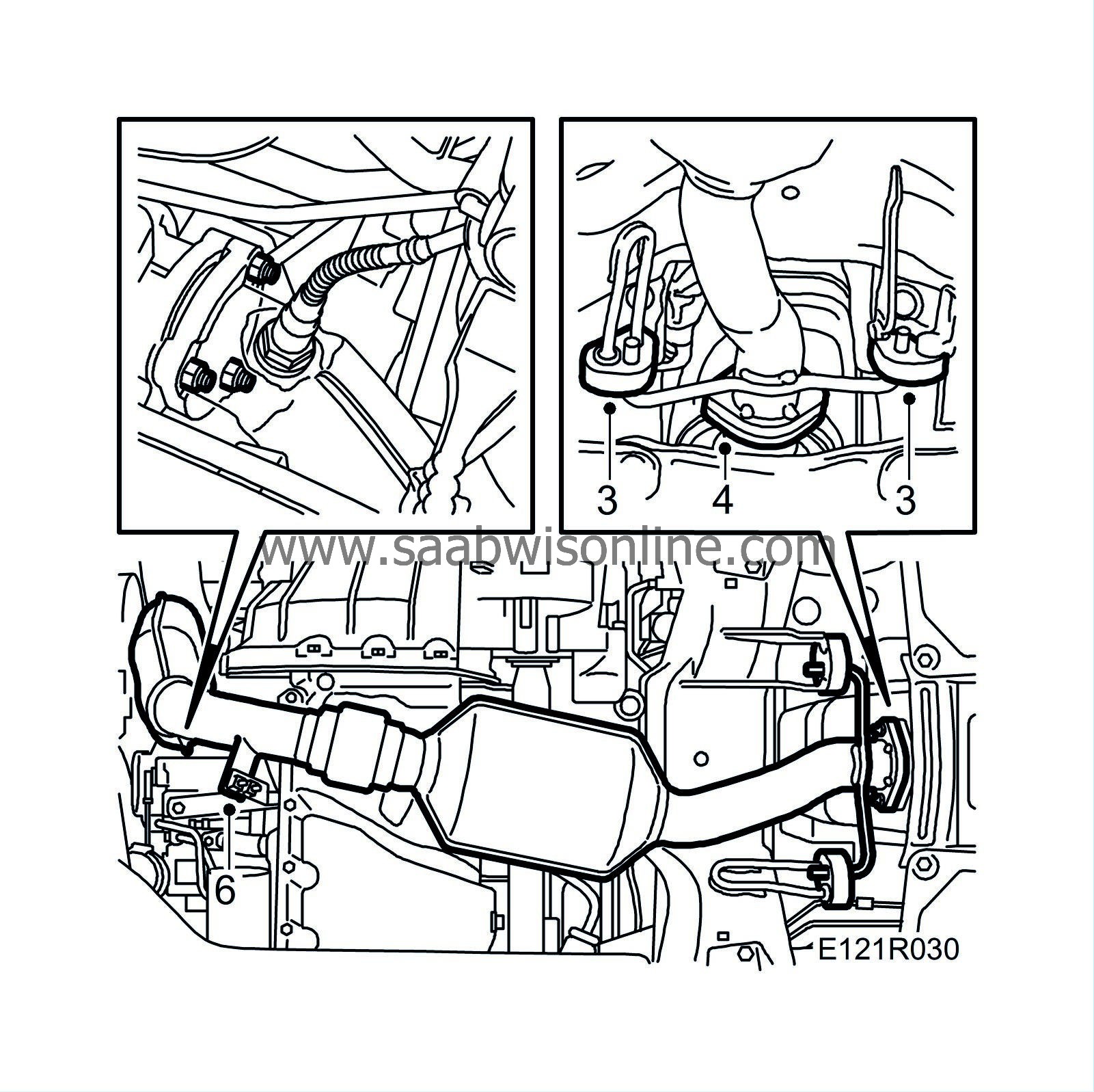
Fit the front pipe with rubber mountings and clips.
|
|
| 4. |
Fit the nuts for the rear pipe joints.
Tightening torque 22 Nm (16 lbf ft) |
|
| 5. |
Fit the lower nut on the turbocharger.
|
|
| 6. |
Fit the stay securing the front pipe to the engine.
Tightening torque 25 Nm (19 lbf ft) |
|
| 7. |
Feed up the oxygen sensor cables and lower the car.
|
|
| 8. |
Release the strain on the lifting beam and remove it.
|
|
| 9. |
Tighten to torque the bolts retaining the engine mounting.
Tightening torque 26 Nm (19 lbf ft). 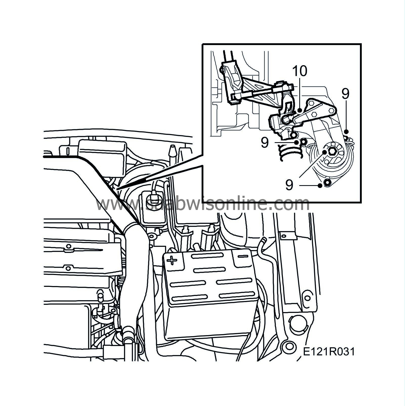
|
|
| 10. |
Fit the gear linkage to the engine mounting bracket.
|
|
| 11. |
Fit the engine mounting's upper retaining nut.
Tightening torque 47 Nm (35 lbf ft). |
|
| 12. |
Fit the two upper nuts to the exhaust system.
Tightening torque 24 Nm (18 lbf ft) 
|
|
| 13. |
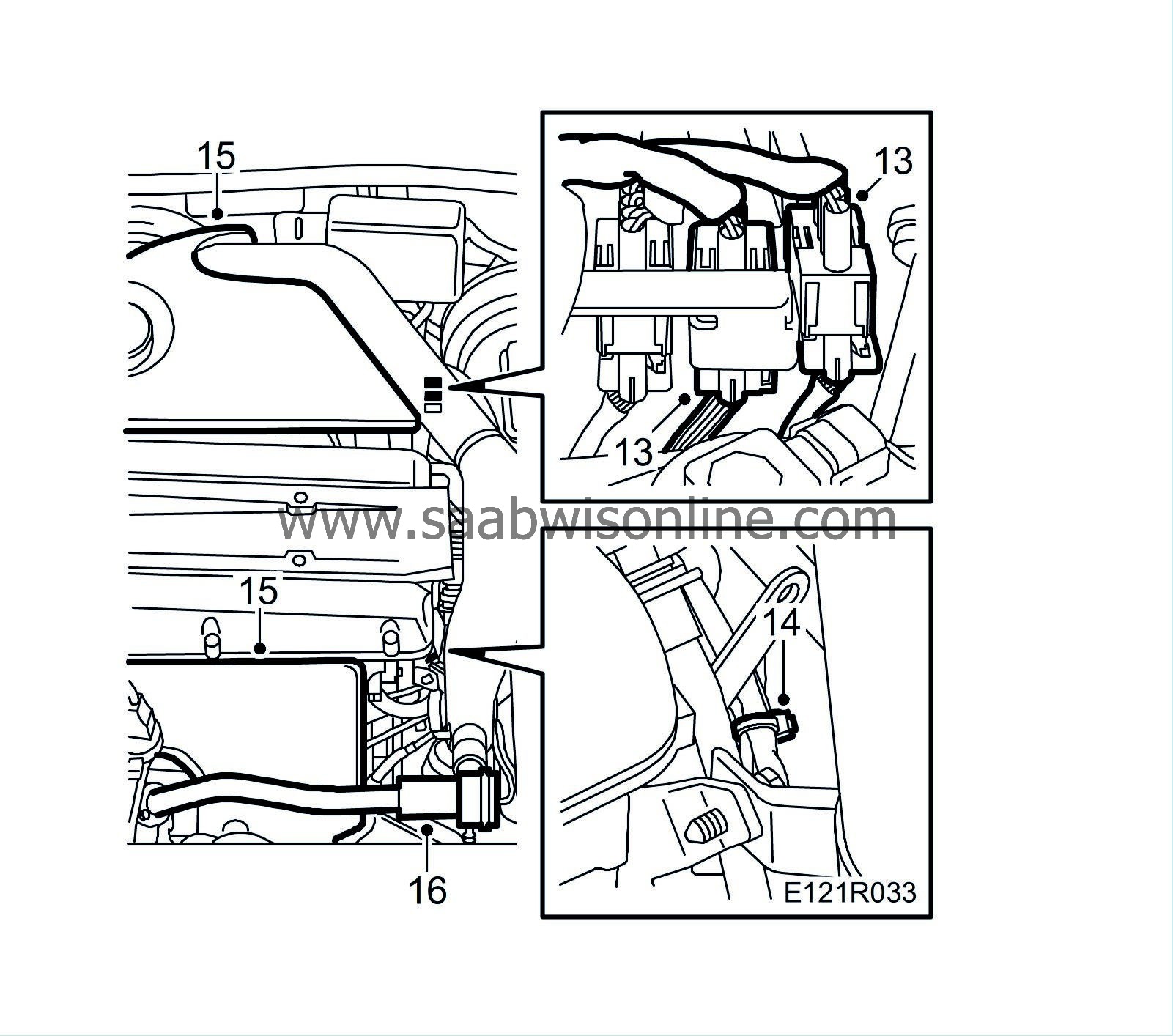
Pull out the oxygen sensor cables and plug in the connectors.
|
|
| 14. |
Secure the cables with a cable tie.
|
|
| 15. |
Fit the upper engine cover and the heat shield over the exhaust manifold.
|
|
| 16. |
Lubricate the O-ring on the bypass pipe with acid-free petroleum jelly and fit the pipe with the valve and vacuum hose.
Tightening torque 8 Nm (6 lbf ft) |
|
| 17. |
Connect the negative battery lead and fit the cover over the battery.
Calibrate the ACC. Set the clock and, were applicable, enter the radio code. |
|
| Marking the modification identity plate |
Mark box C2 on the modification identity plate after completing this procedure. If the work was carried out by the importer, mark the box with a "7". If done by a dealer, mark it with an "8".
| Time/Warranty information |
See separate information.

